EnGenius Technologies ENS200 Secured Wireless Access Point User Manual ENS200
EnGenius Technologies Secured Wireless Access Point ENS200
Contents
- 1. User Man (ENS200)-1
- 2. User Man (ENS200)-2
- 3. User Man (ERA150)
- 4. User Man (FAP-112B)
User Man (ENS200)-2
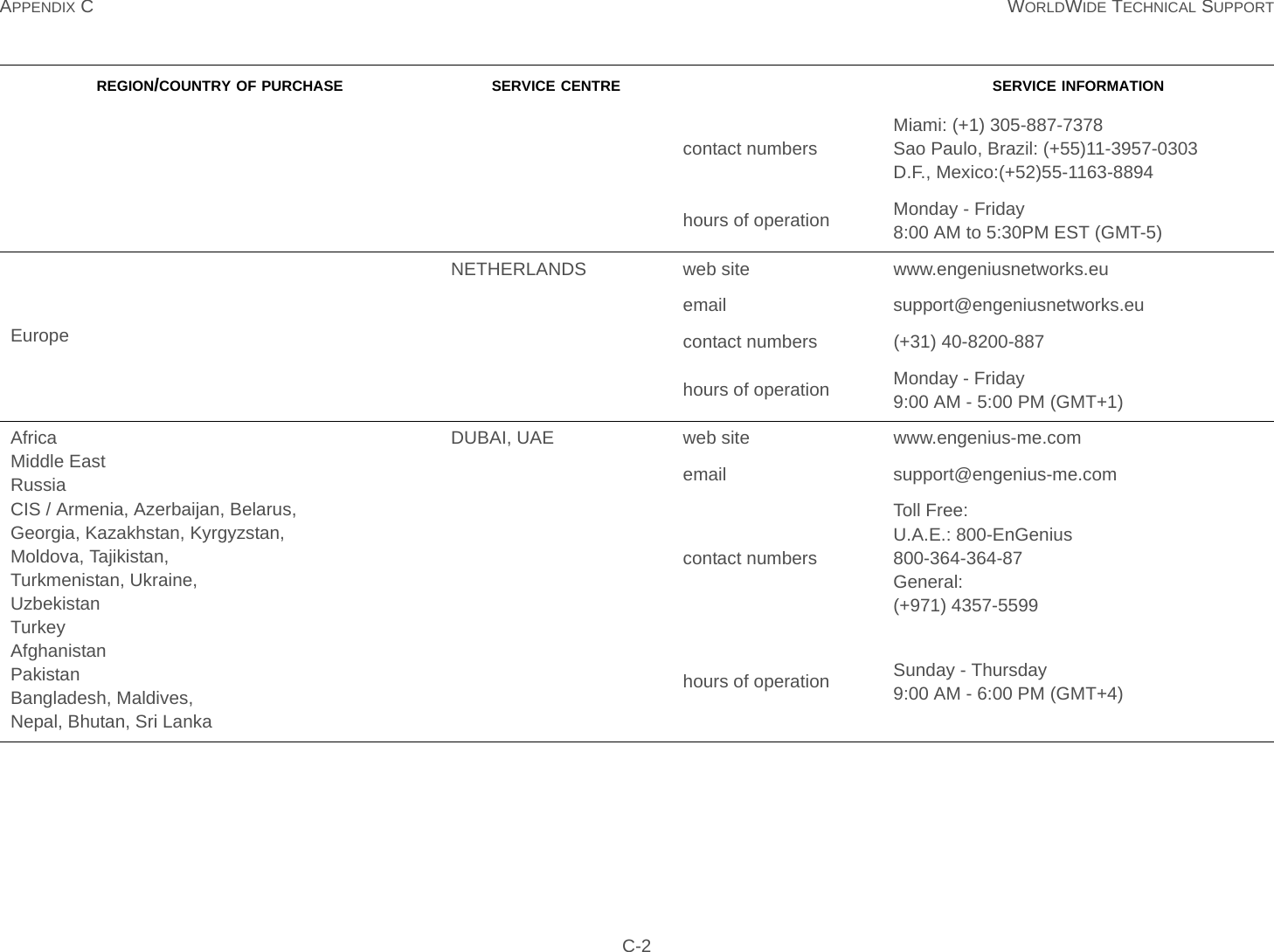
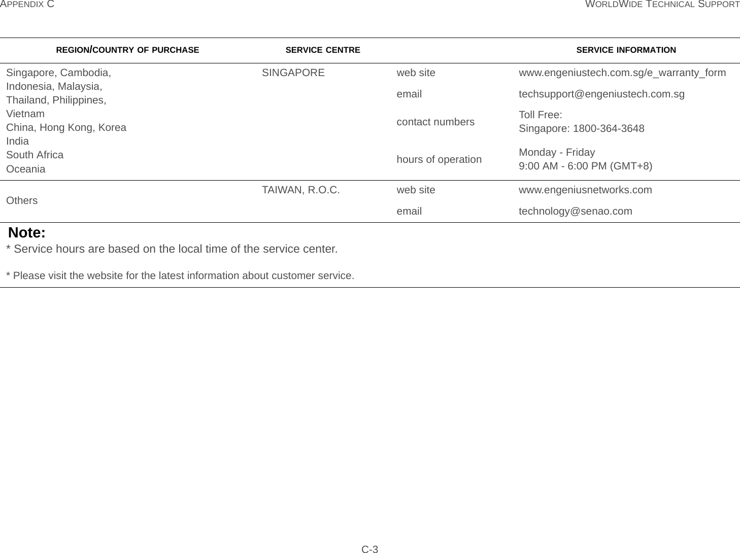
![APPENDIX C WORLDWIDE TECHNICAL SUPPORT C-1Appendix CWorldWide Technical SupportREGION/COUNTRY OF PURCHASE SERVICE CENTRE SERVICE INFORMATIONCanadaCANADA web site www.engeniuscanada.comemail rma@engeniuscanada.comcontact numbers Toll Free: (+1) 888-397-2788Local: (+1) 905-940-8181hours of operation Monday - Friday9:00AM to 5:30PM EST (GMT-5)USALOS ANGELES, USA web site www.engeniustech.comemail support@engeniustech.comcontact numbers Toll Free: (+1) 888-735-7888Local: (+1) 714-432-8668hours of operation Monday - Friday8:00 AM to 4:30 PM PST (GMT-8)Mexico, Central and Southern America MIAMI, USA web site [ES] es.engeniustech.com[PT] pg.engeniustech.comemail miamisupport@engeniustech.com](https://usermanual.wiki/EnGenius-Technologies/ENS200.User-Man-ENS200-2/User-Guide-1848619-Page-52.png)