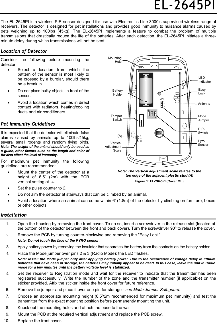
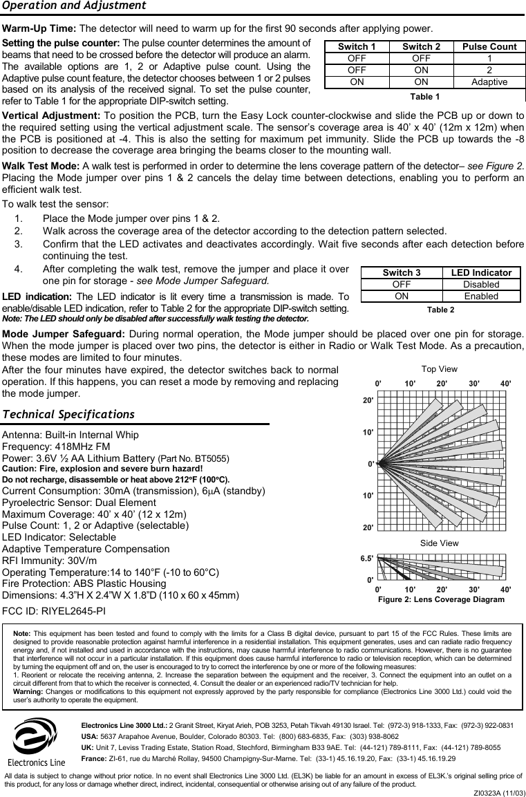
Electronics Line 3000 EL2645-PI PIR Motion Detector User Manual EL 2645PI

Electronics Line 3000 Ltd. PIR Motion Detector EL 2645PI

Users Manual

EL-2645PI The EL-2645PI is a wireless PIR sensor designed for use with Electronics Line 3000’s supervised wireless range of receivers. The detector is designed for pet installations and provides good immunity to nuisance alarms caused by pets weighing up to 100lbs (45kg). The EL-2645PI implements a feature to combat the problem of multiple transmissions that drastically reduce the life of the batteries. After each detection, the EL-2645PI initiates a three-minute delay during which transmissions will not be sent. Location of Detector Consider the following before mounting the detector: •  Select a location from which the pattern of the sensor is most likely to be crossed by a burglar, should there be a break in. •  Do not place bulky objects in front of the sensor. •  Avoid a location which comes in direct contact with radiators, heating/cooling ducts and air conditioners. Pet Immunity Guidelines It is expected that the detector will eliminate false alarms caused by animals up to 100lbs/45kg, several small rodents and random flying birds. Note: The weight of the animal should only be used as a guide, other factors such as the length and color of fur also affect the level of immunity.  For maximum pet immunity the following guidelines are recommended: •  Mount the center of the detector at a height of 6.5’ (2m) with the PCB vertical setting at -4. •  Set the pulse counter to 2. •  Do not aim the detector at stairways that can be climbed by an animal. • Avoid a location where an animal can come within 6’ (1.8m) of the detector by climbing on furniture, boxes or other objects. Installation 1.  Open the housing by removing the front cover. To do so, insert a screwdriver in the release slot (located at the bottom of the detector between the front and back cover). Turn the screwdriver 90º to release the cover. 2.  Remove the PCB by turning counter-clockwise and removing the "Easy Lock".  Note: Do not touch the face of the PYRO sensor. 3.  Apply battery power by removing the insulator that separates the battery from the contacts on the battery holder. 4.  Place the Mode jumper over pins 2 & 3 (Radio Mode); the LED flashes.  Note: Install the Mode jumper only after applying battery power. Due to the occurrence of voltage delay in lithium batteries that have been in storage, the batteries may initially appear to be dead. In this case, leave the unit in Radio mode for a few minutes until the battery voltage level is stabilized.  5.  Set the receiver to Registration mode and wait for the receiver to indicate that the transmitter has been registered successfully. Write the number of the zone and the transmitter number (if applicable) on the sticker provided. Affix the sticker inside the front cover for future reference. 6.  Remove the jumper and place it over one pin for storage - see Mode Jumper Safeguard. 7. Choose an appropriate mounting height (6.5’/2m recommended for maximum pet immunity) and test the transmitter from the exact mounting position before permanently mounting the unit. 8.  Knock out the mounting holes and attach the base to the wall. 9.  Mount the PCB at the required vertical adjustment and replace the PCB screw. 10.  Replace the front cover. Note: The Vertical adjustment scale relates to the  top edge of the adjacent plastic stud (A) Figure 1: EL-2645PI (Cover Off) LED  Indicator Easy Lock Mode Jumper Pyro Sensor Antenna BatteryHolderMountingHoleTamperSwitchVerticalAdjustmentScaleDIP- Switch
Operation and Adjustment Warm-Up Time: The detector will need to warm up for the first 90 seconds after applying power. Setting the pulse counter: The pulse counter determines the amount of beams that need to be crossed before the detector will produce an alarm. The available options are 1, 2 or Adaptive pulse count. Using the Adaptive pulse count feature, the detector chooses between 1 or 2 pulses based on its analysis of the received signal. To set the pulse counter, refer to Table 1 for the appropriate DIP-switch setting. Vertical Adjustment: To position the PCB, turn the Easy Lock counter-clockwise and slide the PCB up or down to the required setting using the vertical adjustment scale. The sensor’s coverage area is 40’ x 40’ (12m x 12m) when the PCB is positioned at -4. This is also the setting for maximum pet immunity. Slide the PCB up towards the -8 position to decrease the coverage area bringing the beams closer to the mounting wall. Walk Test Mode: A walk test is performed in order to determine the lens coverage pattern of the detector– see Figure 2. Placing the Mode jumper over pins 1 & 2 cancels the delay time between detections, enabling you to perform an efficient walk test.  To walk test the sensor:  1.  Place the Mode jumper over pins 1 & 2. 2.  Walk across the coverage area of the detector according to the detection pattern selected.  3.  Confirm that the LED activates and deactivates accordingly. Wait five seconds after each detection before continuing the test. 4.  After completing the walk test, remove the jumper and place it over one pin for storage - see Mode Jumper Safeguard. LED indication: The LED indicator is lit every time a transmission is made. To enable/disable LED indication, refer to Table 2 for the appropriate DIP-switch setting. Note: The LED should only be disabled after successfully walk testing the detector. Mode Jumper Safeguard: During normal operation, the Mode jumper should be placed over one pin for storage. When the mode jumper is placed over two pins, the detector is either in Radio or Walk Test Mode. As a precaution, these modes are limited to four minutes.  After the four minutes have expired, the detector switches back to normal operation. If this happens, you can reset a mode by removing and replacing the mode jumper. Technical Specifications Antenna: Built-in Internal Whip Frequency: 418MHz FM Power: 3.6V ½ AA Lithium Battery (Part No. BT5055) Caution: Fire, explosion and severe burn hazard! Do not recharge, disassemble or heat above 212°F (100°C). Current Consumption: 30mA (transmission), 6µA (standby) Pyroelectric Sensor: Dual Element Maximum Coverage: 40’ x 40’ (12 x 12m) Pulse Count: 1, 2 or Adaptive (selectable) LED Indicator: Selectable Adaptive Temperature Compensation RFI Immunity: 30V/m Operating Temperature:14 to 140°F (-10 to 60°C) Fire Protection: ABS Plastic Housing Dimensions: 4.3”H X 2.4”W X 1.8”D (110 x 60 x 45mm) FCC ID: RIYEL2645-PI Side View Top View Switch 1  Switch 2  Pulse Count OFF OFF  1 OFF ON  2  ON ON Adaptive Table 1 Figure 2: Lens Coverage Diagram Switch 3  LED Indicator OFF Disabled ON Enabled Table 2 Electronics Line 3000 Ltd.: 2 Granit Street, Kiryat Arieh, POB 3253, Petah Tikvah 49130 Israel. Tel:  (972-3) 918-1333, Fax:  (972-3) 922-0831 USA: 5637 Arapahoe Avenue, Boulder, Colorado 80303. Tel:  (800) 683-6835, Fax:  (303) 938-8062 UK: Unit 7, Leviss Trading Estate, Station Road, Stechford, Birmingham B33 9AE. Tel:  (44-121) 789-8111, Fax:  (44-121) 789-8055 France: ZI-61, rue du Marché Rollay, 94500 Champigny-Sur-Marne. Tel:  (33-1) 45.16.19.20, Fax:  (33-1) 45.16.19.29 ZI0323A (11/03)All data is subject to change without prior notice. In no event shall Electronics Line 3000 Ltd. (EL3K) be liable for an amount in excess of EL3K.’s original selling price ofthis product, for any loss or damage whether direct, indirect, incidental, consequential or otherwise arising out of any failure of the product. Note: This equipment has been tested and found to comply with the limits for a Class B digital device, pursuant to part 15 of the FCC Rules. These limits aredesigned to provide reasonable protection against harmful interference in a residential installation. This equipment generates, uses and can radiate radio frequencyenergy and, if not installed and used in accordance with the instructions, may cause harmful interference to radio communications. However, there is no guarantee that interference will not occur in a particular installation. If this equipment does cause harmful interference to radio or television reception, which can be determinedby turning the equipment off and on, the user is encouraged to try to correct the interference by one or more of the following measures: 1. Reorient or relocate the receiving antenna, 2. Increase the separation between the equipment and the receiver, 3. Connect the equipment into an outlet on acircuit different from that to which the receiver is connected, 4. Consult the dealer or an experienced radio/TV technician for help. Warning: Changes or modifications to this equipment not expressly approved by the party responsible for compliance (Electronics Line 3000 Ltd.) could void the user’s authority to operate the equipment.

Navigation menu