Electronics Line 3000 EL2635 Repeater for Wireless Sensors User Manual EL 2635
Electronics Line 3000 Ltd. Repeater for Wireless Sensors EL 2635
UserManual.wiki
>
Electronics Line 3000
>
EL2635 User Manual
Users Manual
Navigation menu
Upload a User Manual
Namespaces
Wiki Guide
HTML
PDF
Info
Views
User Manual
Discussion / Help
Navigation
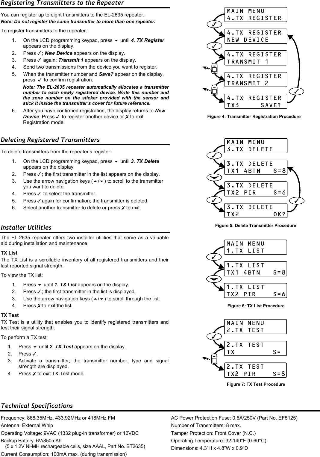
![Introduction The EL-2635 is a wireless repeater designed to extend the range of wireless devices registered to the infiniti control panel. Up to four repeaters can be registered to the control panel with eight transmitters registered to each repeater. The repeater is powered by either 9VAC (via a 110VAC plug-in step down transformer) or 12VDC with a 6V rechargeable backup battery pack. Registration and maintenance tests are performed using a plug-in LCD programming keypad that provides a comprehensive interface to the repeater. Installation 1. Register all wireless devices to the infiniti control panel as explained in the infiniti installation manual. 2. On the control panel, define the detection devices that are intended to transmit via the repeater as follows: • From the Programming menu, select Devices, Zones [911]. • Select the zone you want to program (1-32). • From the zone’s sub-menu, select Repeater [#9]. • Select “Use Repeater”. Note: It is not necessary to define, at the control panel, the keypads and keyfobs that are registered to the repeater. 3. Open the EL-2635’s plastic housing. To do so, remove the two cover screws and lift the front cover away from the base. Figure 2: EL-2635 (cover removed) 4. Connect the antenna provided to the antenna connector. 5. Connect the backup battery pack to the Battery connector. 6. Connect 9VAC (via a 110VAC plug-in step down transformer) or a 12VDC transformer to the Power Input terminal block. 7. All registration and test functions, described in the following sections, are performed from the LCD programming keypad shown in Figure 3. Connect the programming keypad to the Programming Keypad connector. Note: The programming keypad is not able to operate on battery power only. 8. Test the repeater from the required mounting location before permanently mounting the unit. 9. Mount the base to the wall using four screws and replace the front cover. When the tamper switch is open, the bi-color LED provides indication regarding repeater transmission and reception as an aid during the installation procedure – see Table 1. When the tamper switch is closed, the bi-color LED provides indication regarding power status – see Table 2. Registering the Repeater to the Control Panel For the control panel to recognize the repeater, you must register the repeater to the control panel. To register the repeater to the control panel: 1. Set the control panel to Registration mode as follows: • From the Programming menu, select Devices, Repeaters [914]. • Select the repeater you want to register (1-4). • From the repeater’s sub-menu, select Register [#1]. 2. Send two Status transmissions from the repeater as follows: • On the programming keypad, press until 5. STS Transmit appears on the display. • Press . • Press again. 3. Confirm registration to the control panel as follows: • When Save? appears on the control panel’s LCD display, press . AntennaConnectorProgramming Keypad Connector LowerMountingHoleUpper Mounting Hole Lower Mounting Hole LED Indicator ReceiverTamper Switch AC PowerProtection FuseUpperMountingHoleTransmitterFlash Programming Connector Power InputTerminalsWiringHoleFigure 3: LCD Programming Keypad Figure 1: Typical Single Repeater Application LED Indication Description Flashing Green Signal Reception Flashing Red Signal Transmission Table 1: LED Indication (Tamper Open) LED Indication Description Steady Green AC & Battery OK Flashing Red AC Loss Flashing Orange Low Battery Table 2: LED Indication (Tamper Closed) Backup Battery Pack Battery Connector](https://usermanual.wiki/Electronics-Line-3000/EL2635/User-Guide-531447-Page-2.png)