Electronic Controls Design E51-0386-40 Super MOLE® Gold 2 User Manual ECD M O L E MAP Users Help System 3 0 6
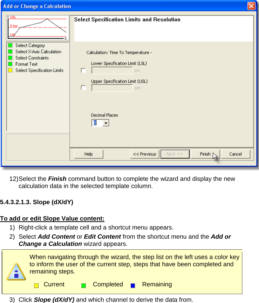
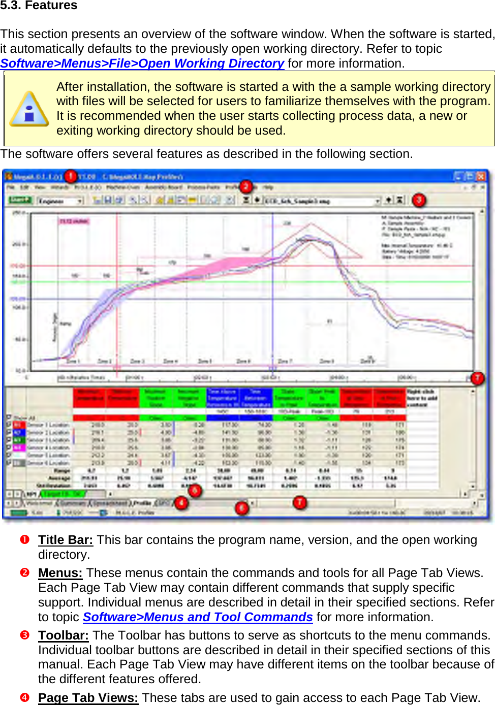
Electronic Controls Design Inc Super MOLE® Gold 2 ECD M O L E MAP Users Help System 3 0 6
Contents
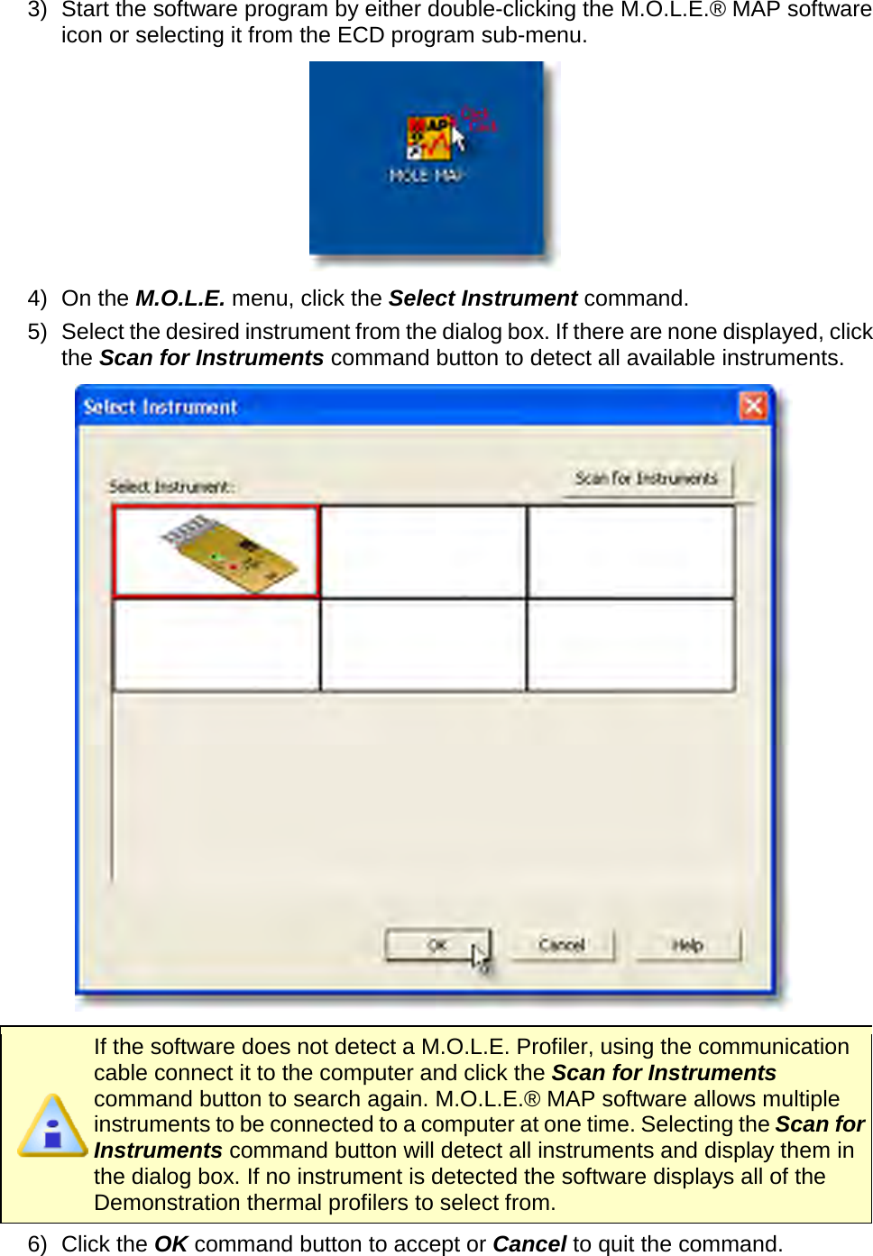
- 1. User Manual part 1 of 3
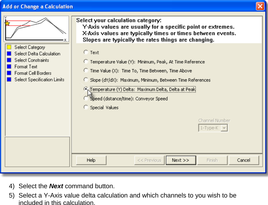
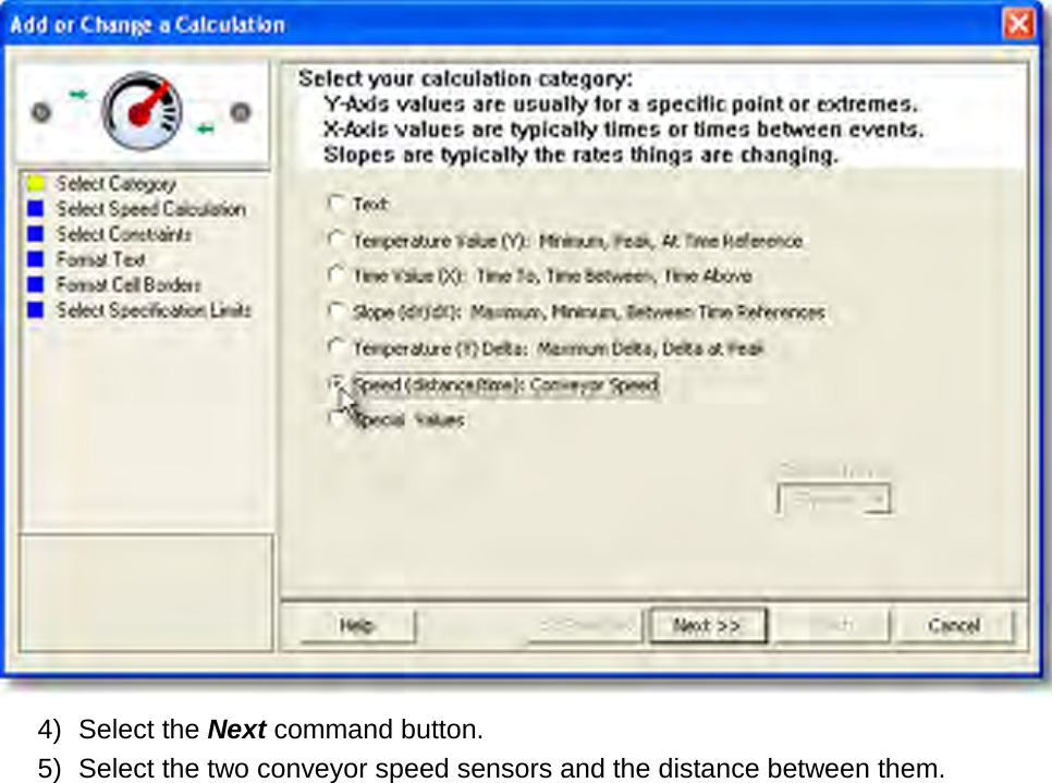
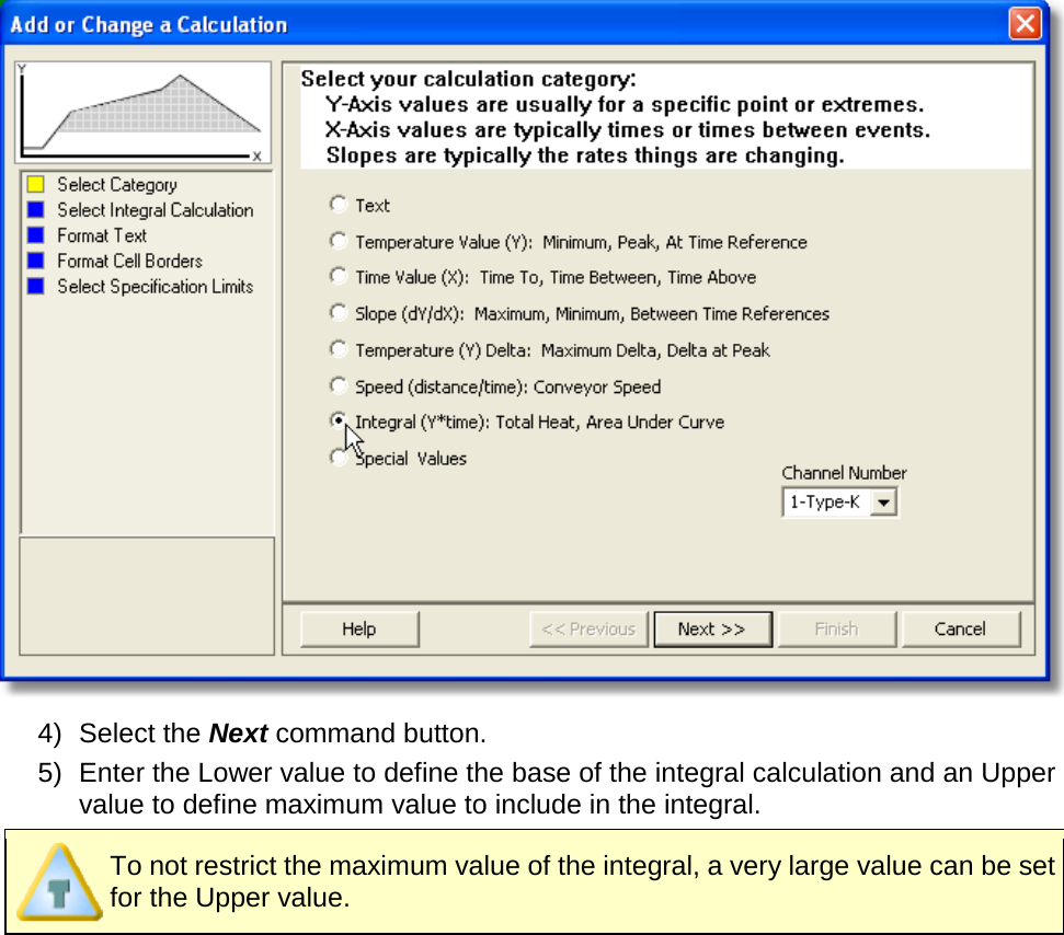
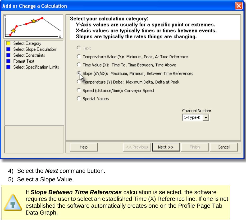
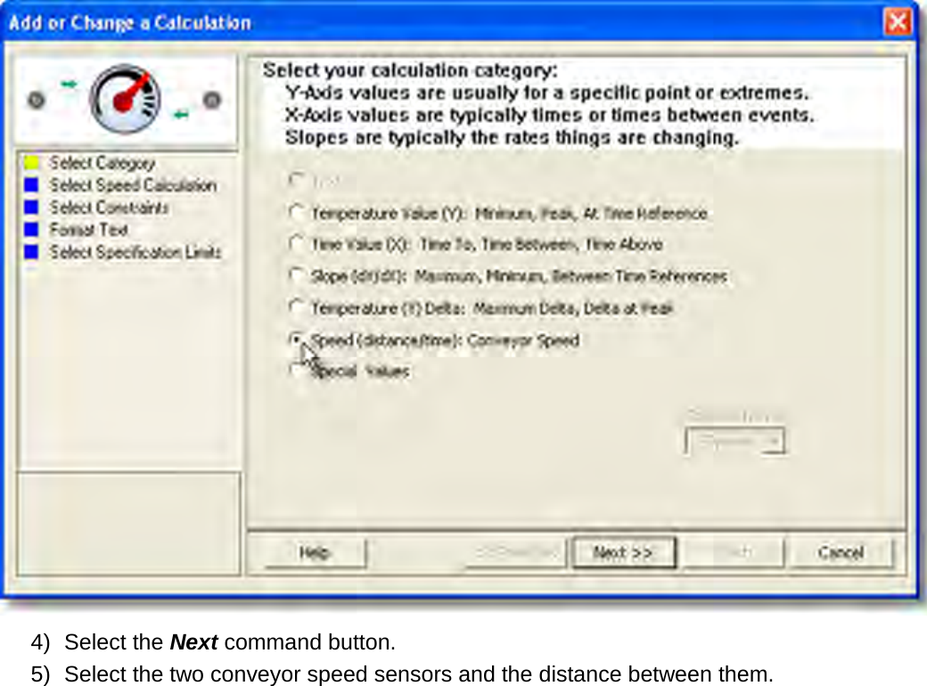
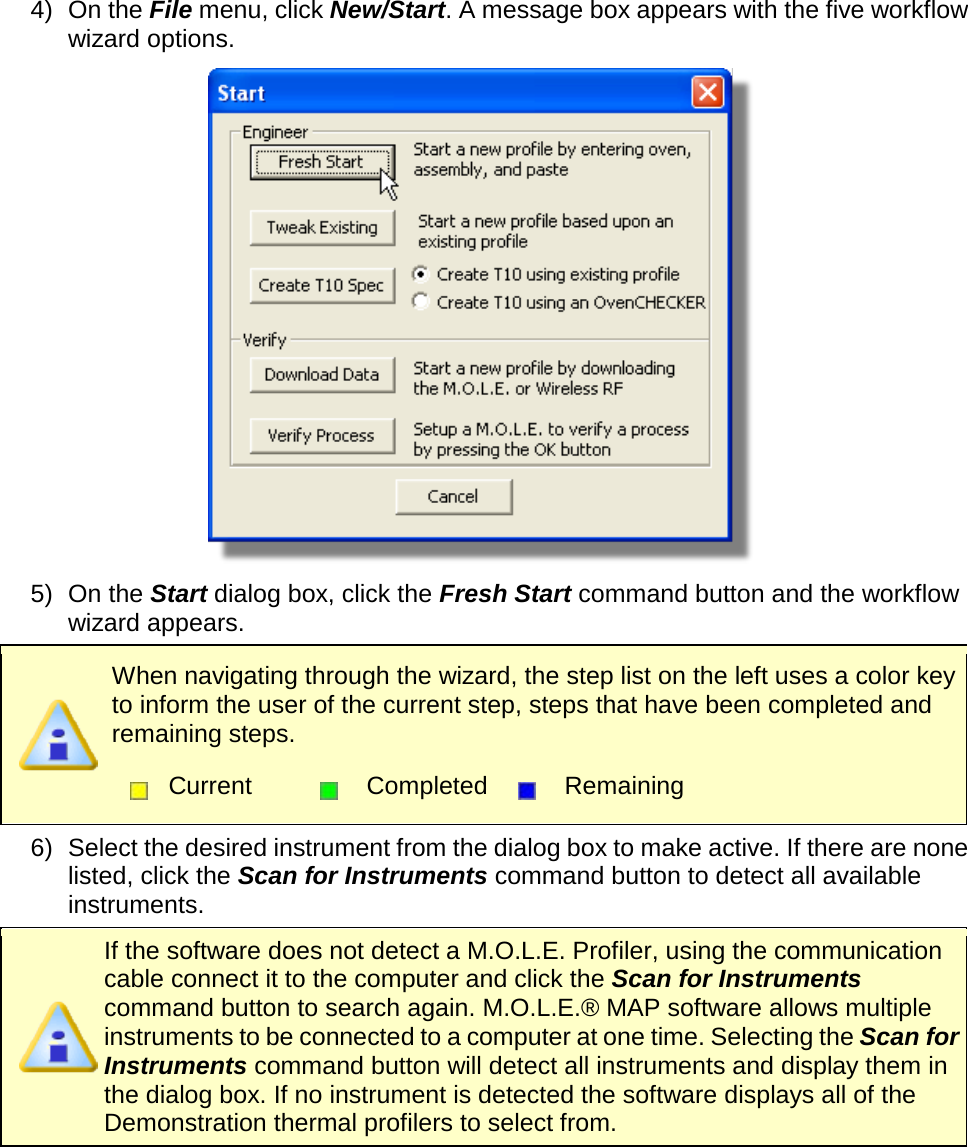
- 2. User Manual part 2 of 3
- 3. User Manual part 3 of 3
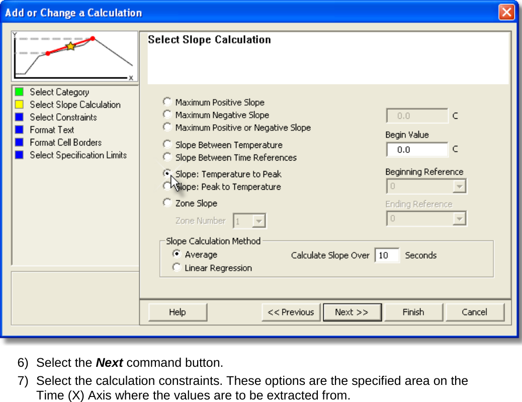
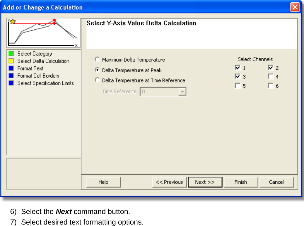
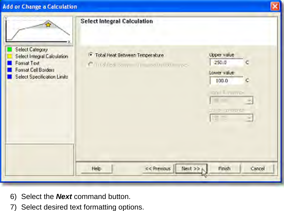
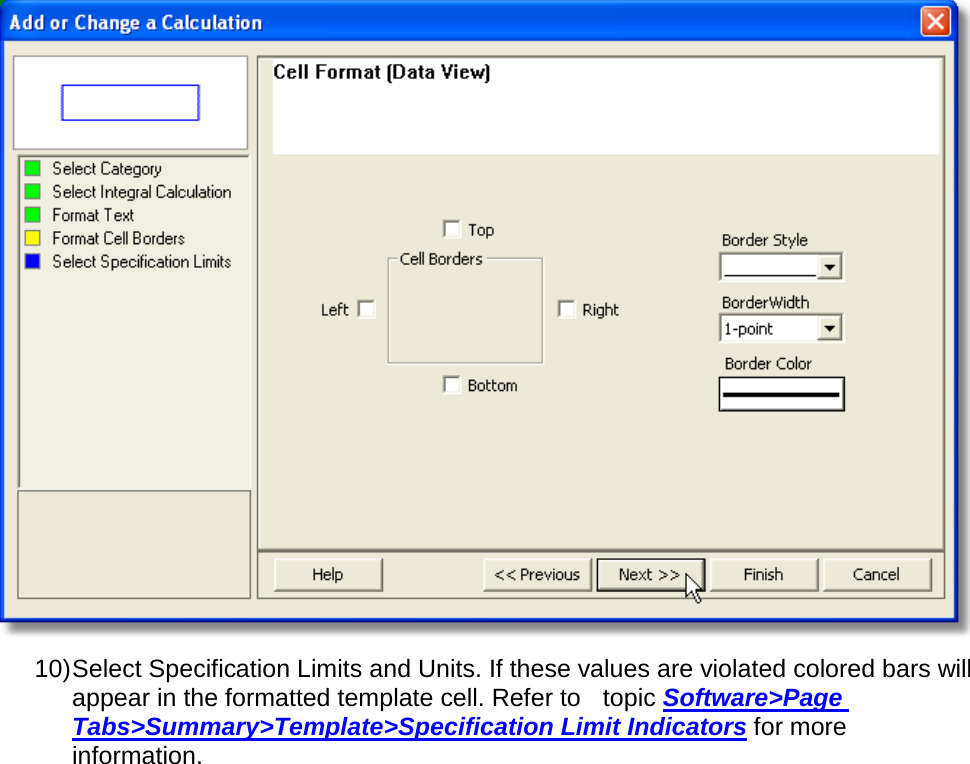
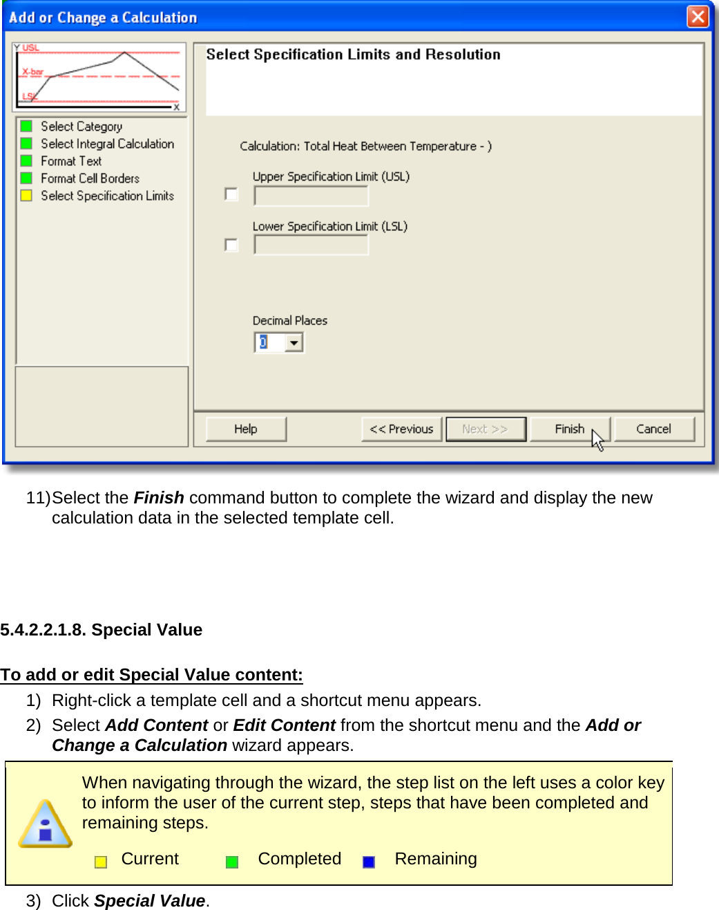
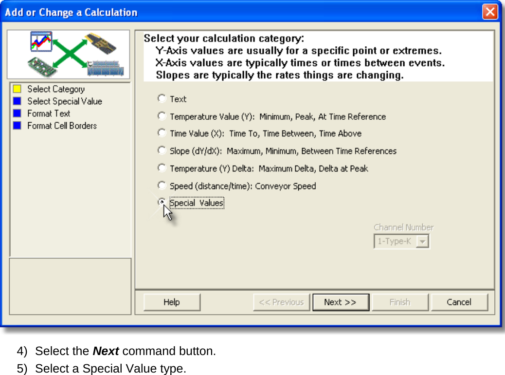
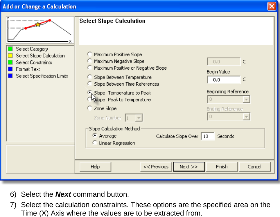
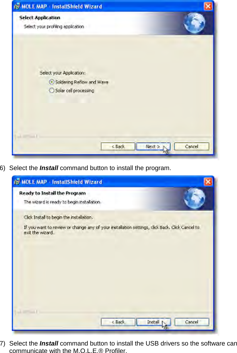
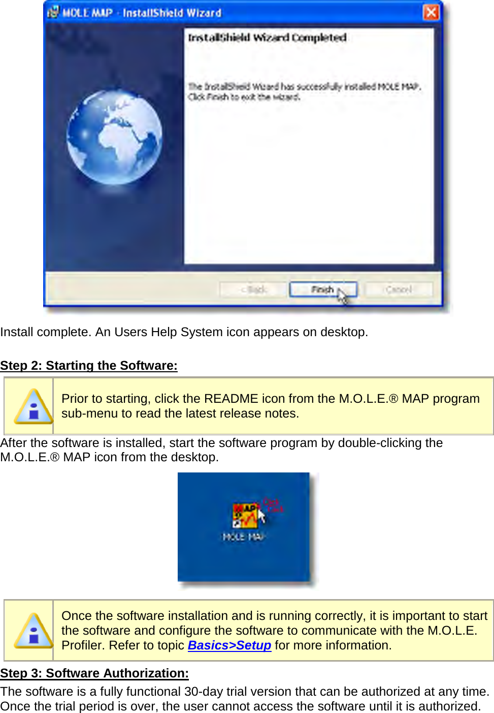
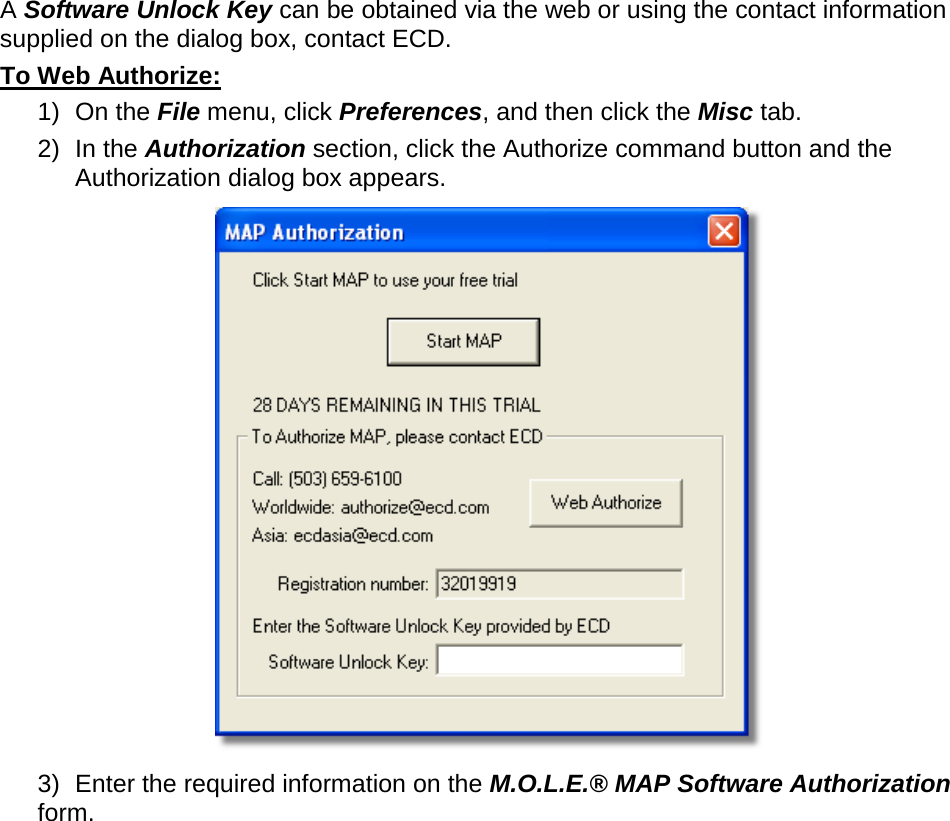
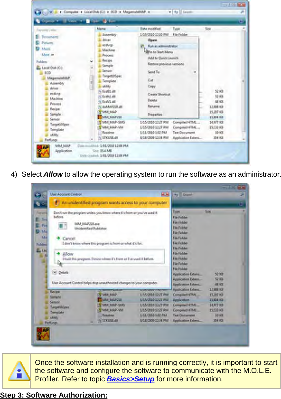
User Manual part 1 of 3
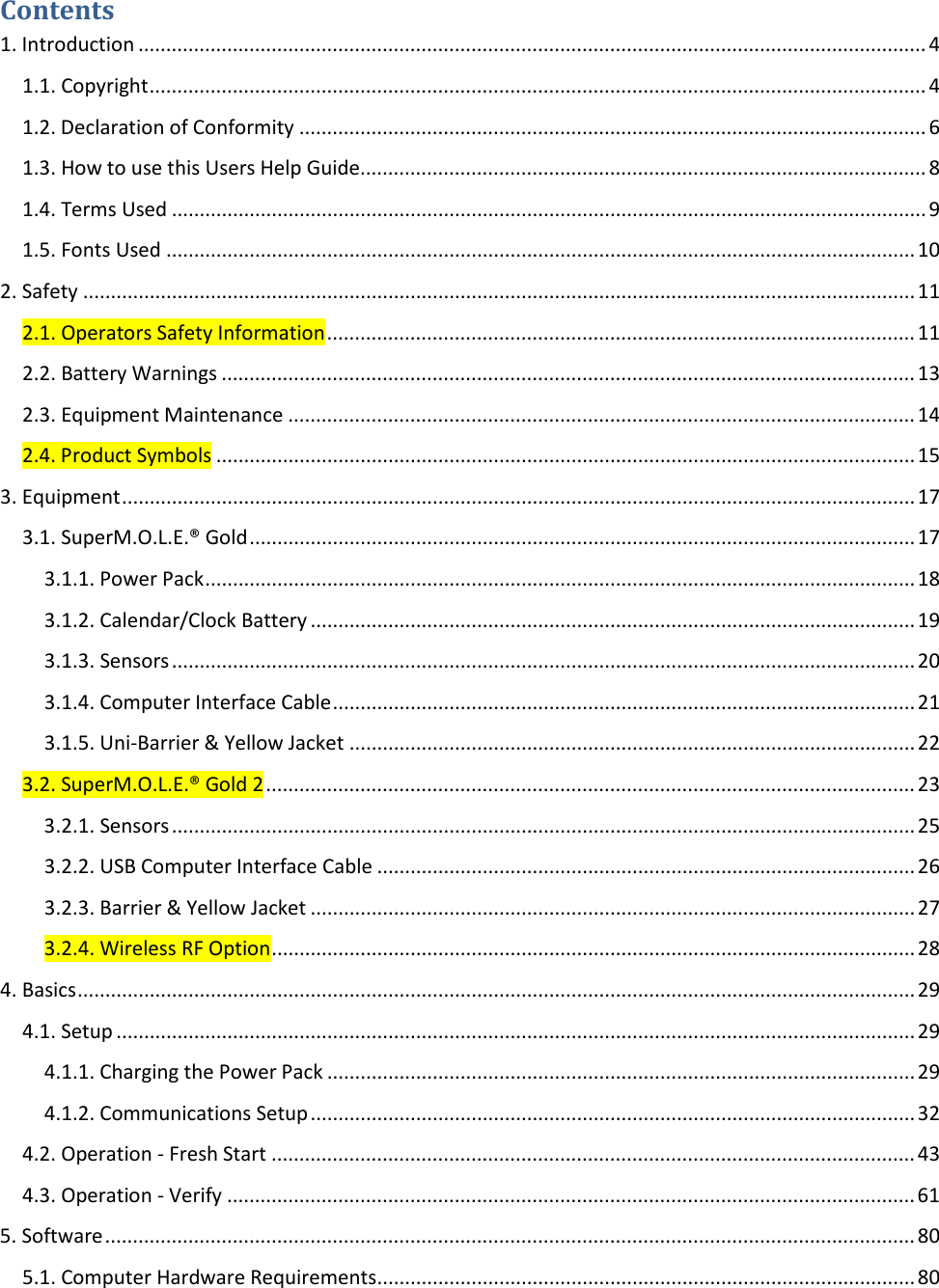


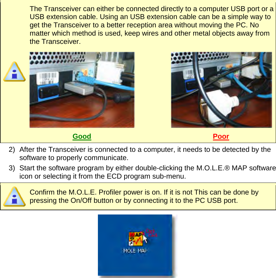
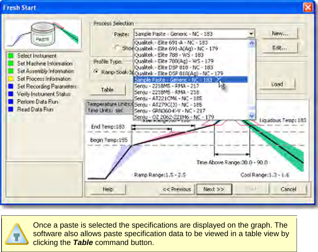
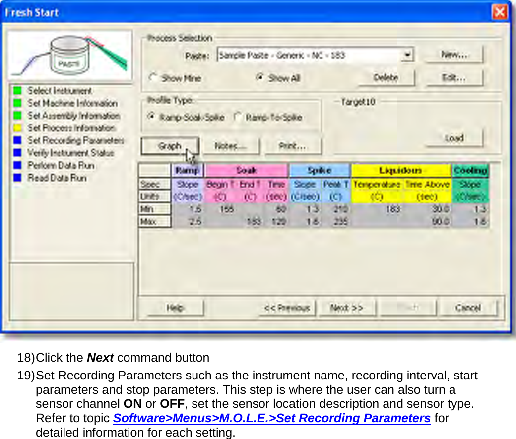
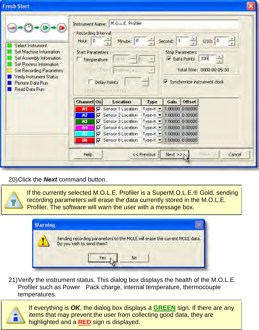
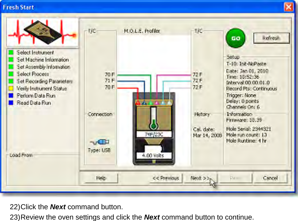
![Wireless RF communication tips (MEGAM.O.L.E.® & SuperM.O.L.E.® Gold 2): RF signals come and go as either the M.O.L.E. Profiler moves through the oven or the Transceiver is moved around like FM radio static as you drive in your car. Moving a few inches in any direction can turn a low signal strength to high signal strength. This gets worse as the Transceiver gets further from the M.O.L.E. Profiler, to a point where no position works. When setting up the Wireless RF system, the transceiver should be placed as close to the machine as practical. A standard USB extension cable can be used to move the Transceiver closer to the machine or up and away from metal or other interference objects. Typically if the Transceiver is 3 meters [10 feet] away from the M.O.L.E. Profiler in a machine any location in the room, reception should be fine. Reception is also often a bit better when the Transceiver is perpendicular to the direction of travel through the machine. Metal objects such as carts, walls, or other equipment in the room will impede transmission. The transmitting Antenna and its proximity to metal can have a big affect. Care should be taken to make sure the Antenna is not laying on metal parts in the machine or barrier box. Keeping the Antenna straight is best. Wireless RF Range](https://usermanual.wiki/Electronic-Controls-Design/E51-0386-40.User-Manual-part-1-of-3/User-Guide-1481865-Page-42.png)
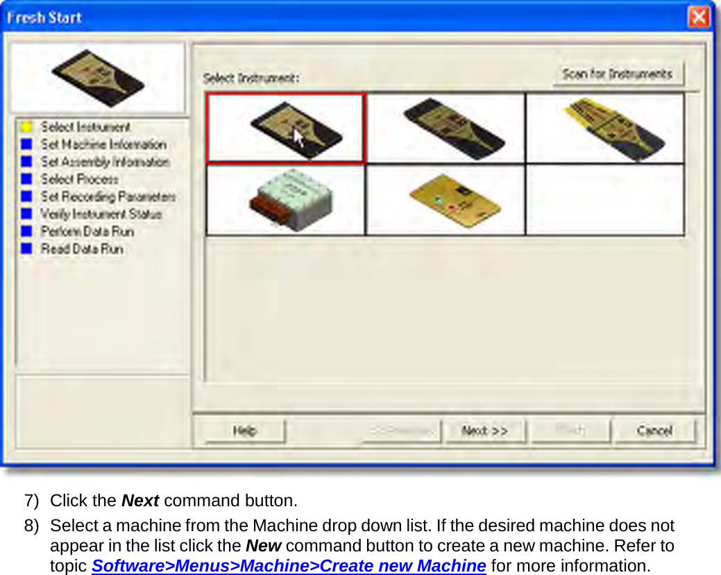


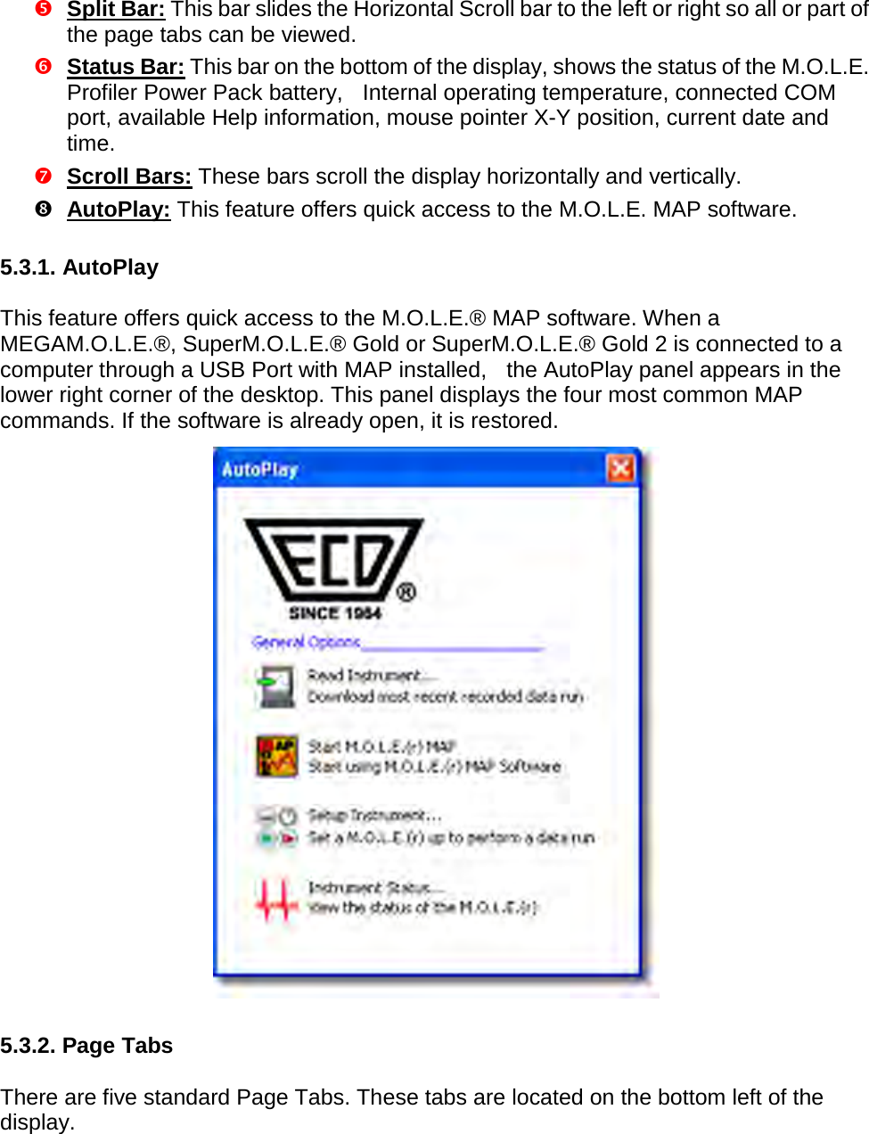
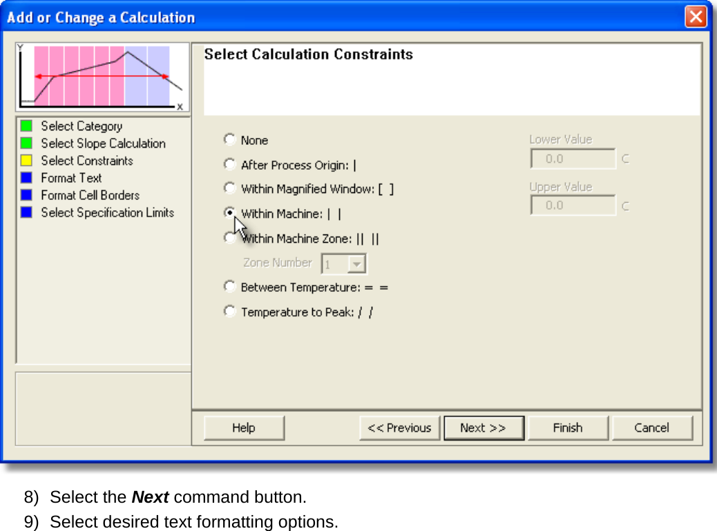
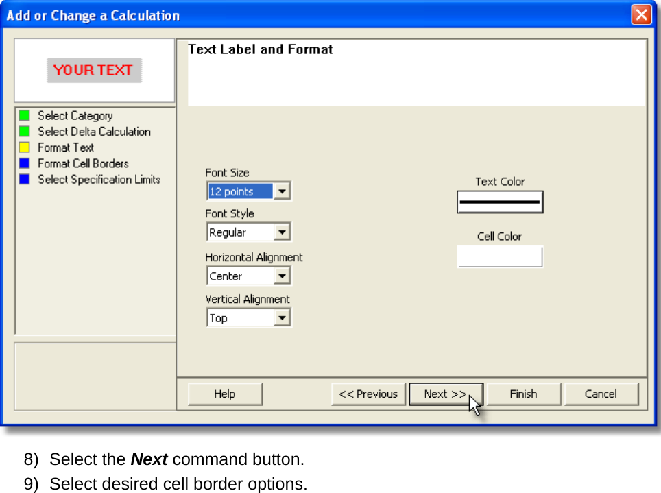
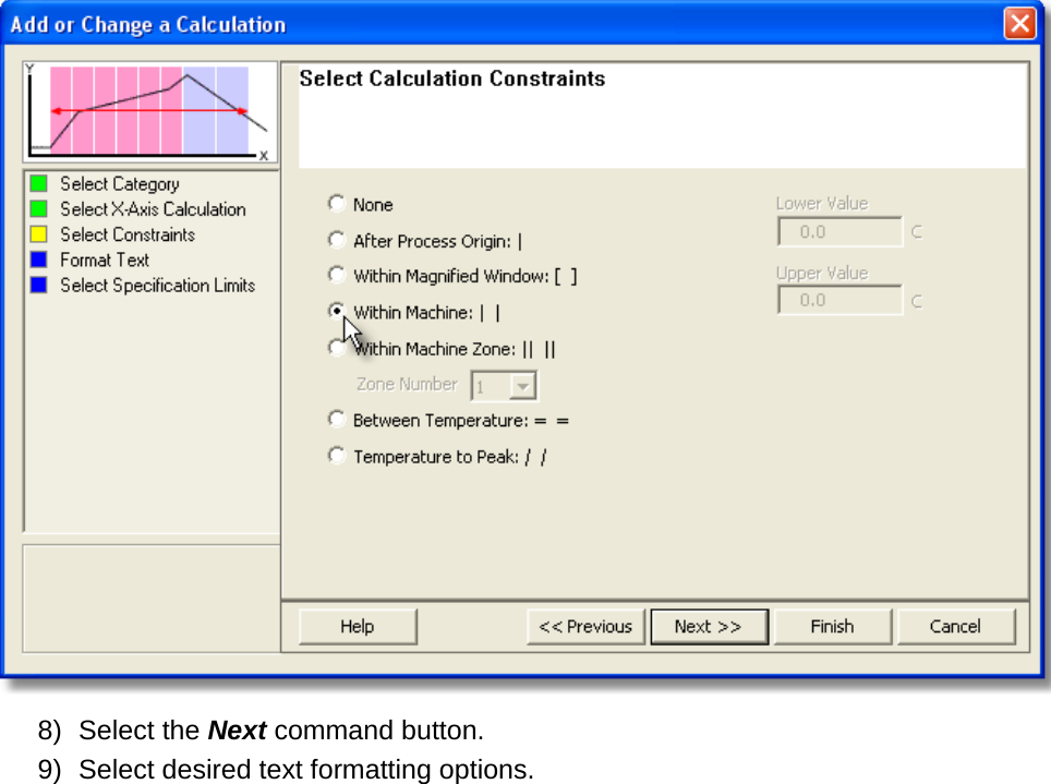
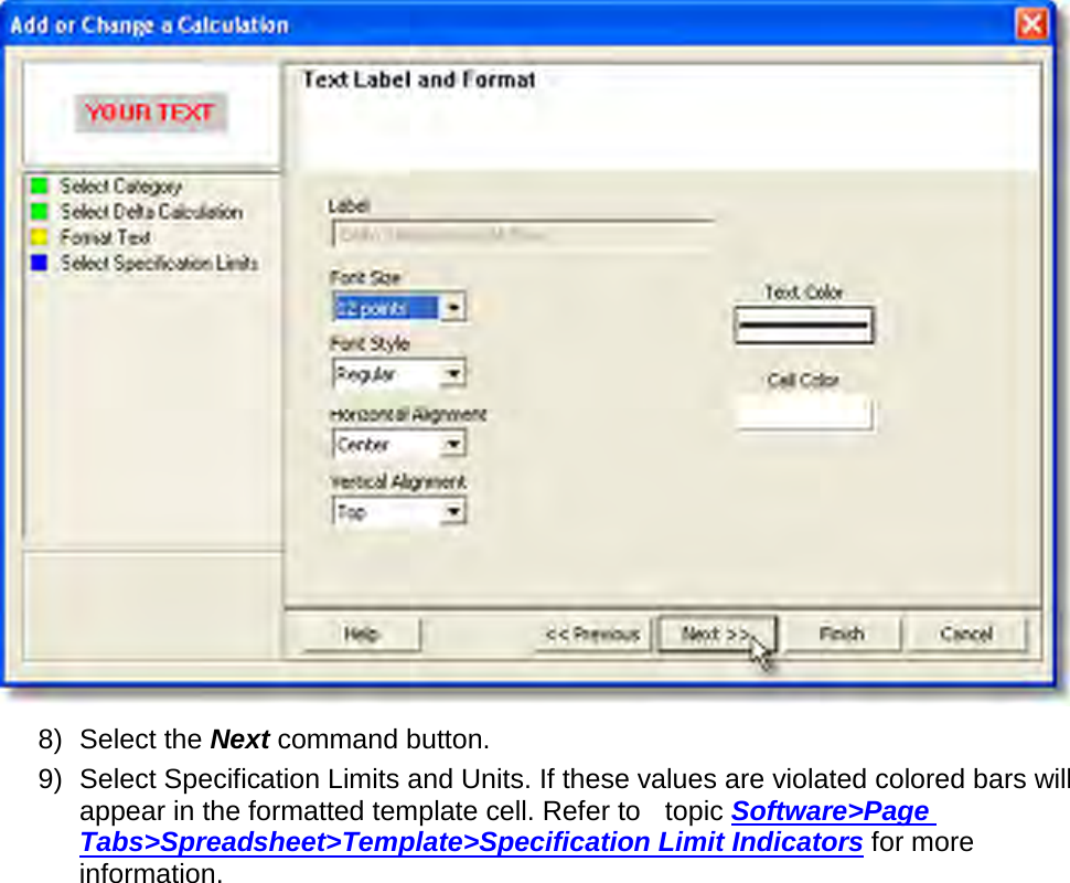
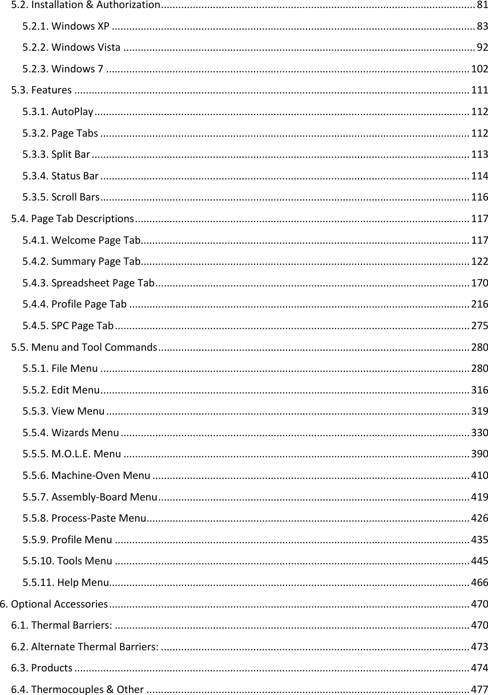
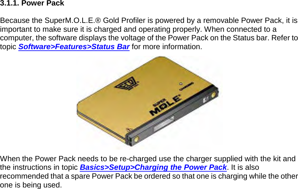
![ Power Pack: This indicator displays the voltage reported by the currently selected M.O.L.E. Profiler. The nominal range for normal MEGAM.O.L.E.®, V-M.O.L.E.® and SuperM.O.L.E.® Gold 2 Profilers is 4.0V to 3.0V and SuperM.O.L.E.® Gold Profiler operation is 5.1V to 4.7V. Temperature: This indicator displays the internal operating temperature reported by the currently selected M.O.L.E. Profiler. If the internal operating temperature is within the acceptable range (0°-40°C [0°-104°F]) the symbol appears in GREEN. When the internal operating temperature is above the acceptable range (41°C> [105.8°F>]), it appears in RED indicating that the M.O.L.E. Profiler has reached the temperature warning zone. M.O.L.E. Profiler Connection: This indicator displays a symbol for the computer communication connection type such as Serial, USB or wireless RF. Instrument User Name: This indicator displays the user configured name for the M.O.L.E. Profiler. Help Information: This indicator displays the action that button performs when the mouse pointer is placed over a Toolbar button or Menu command. Time (X)/Temperature (Y) Readout: This indicator displays the Time and Temperature values of the mouse pointer location on the Profile tab Data Graph. The units displayed for Time and Temperature values are the same as those displayed on the graph.](https://usermanual.wiki/Electronic-Controls-Design/E51-0386-40.User-Manual-part-1-of-3/User-Guide-1481865-Page-115.png)

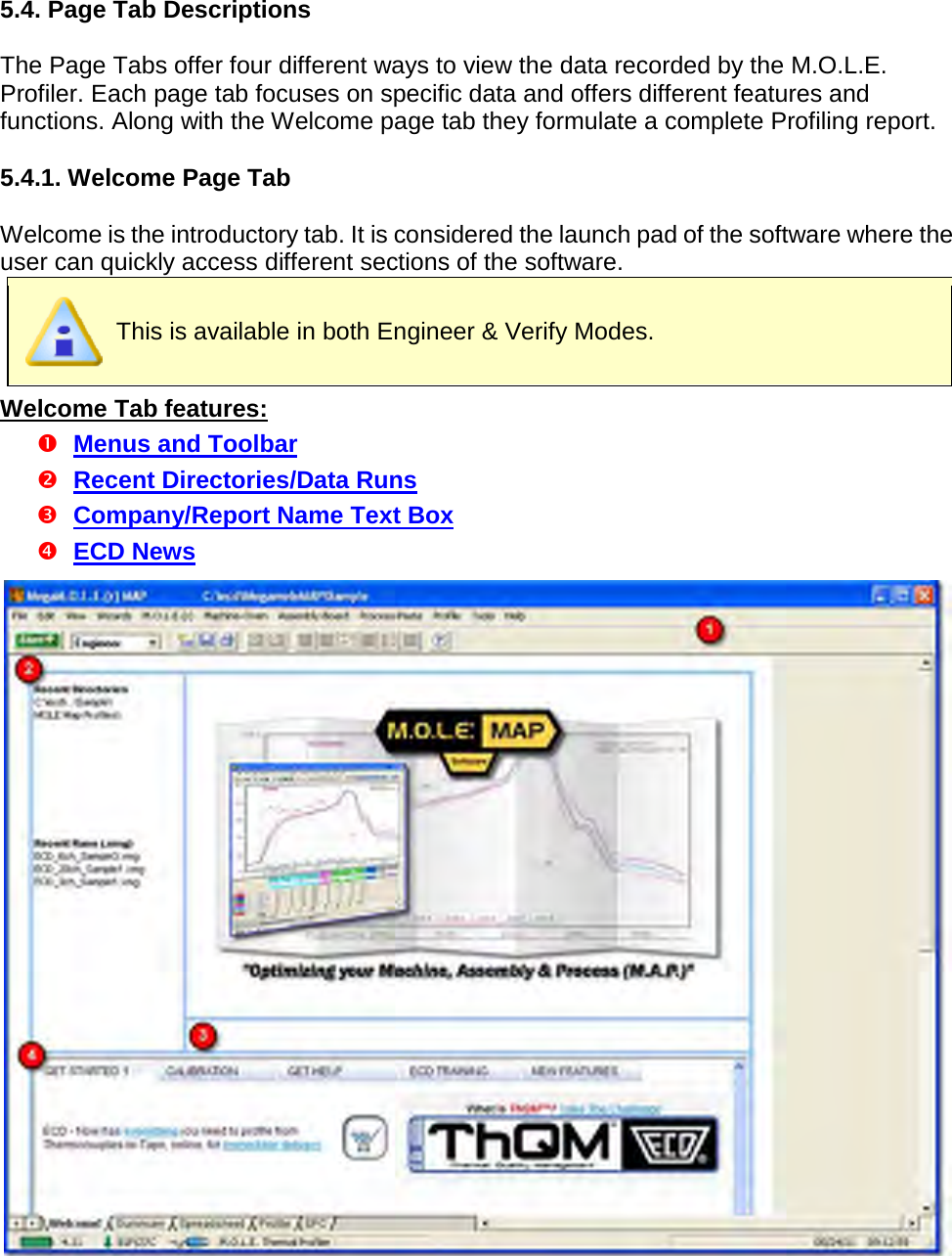

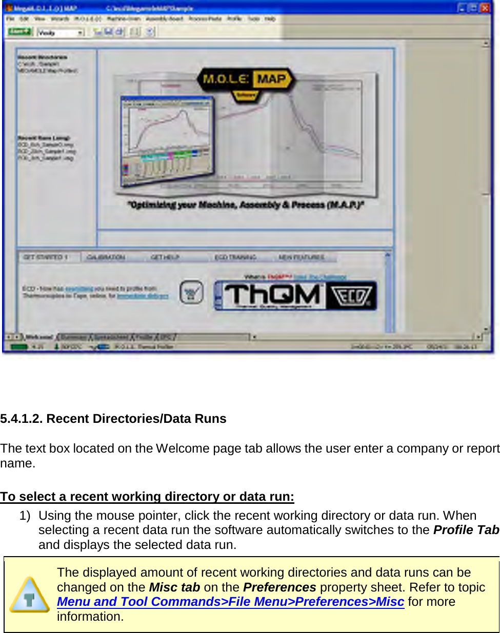
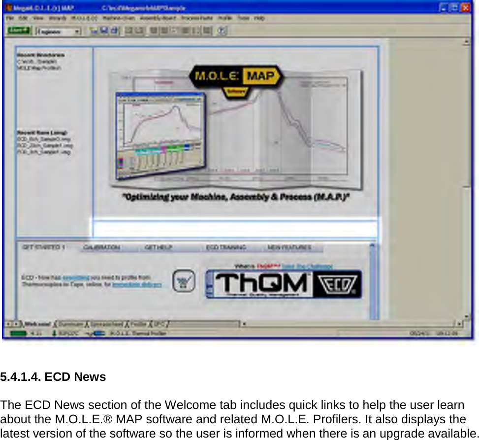
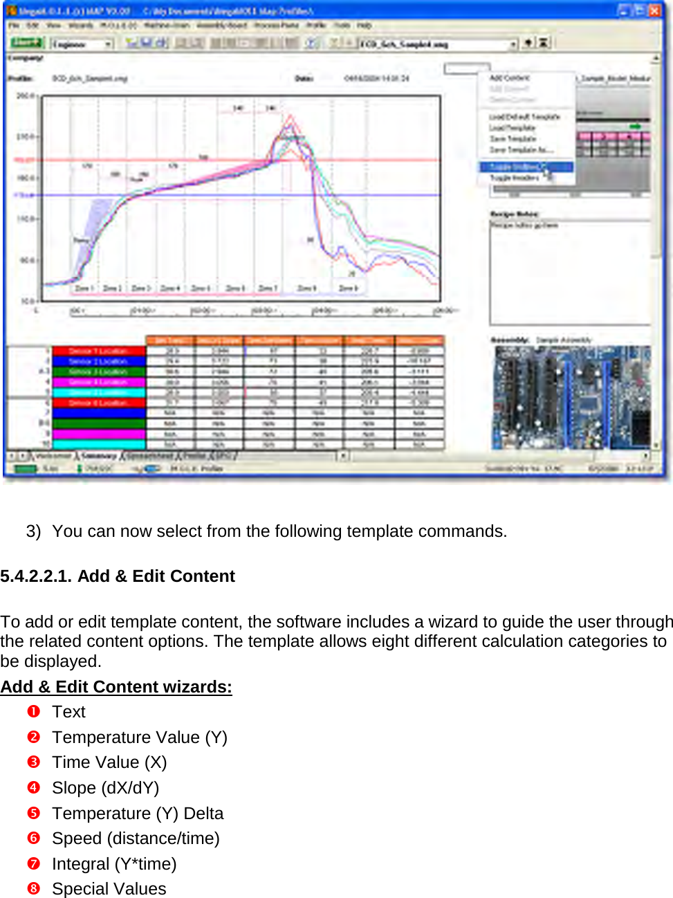
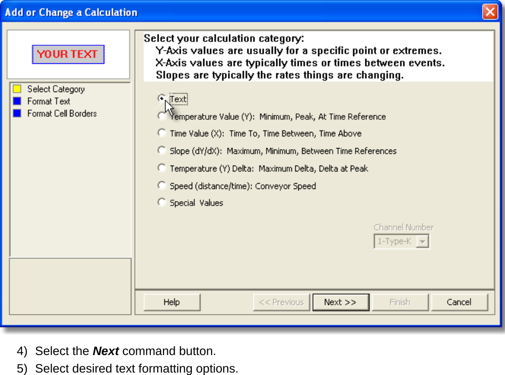
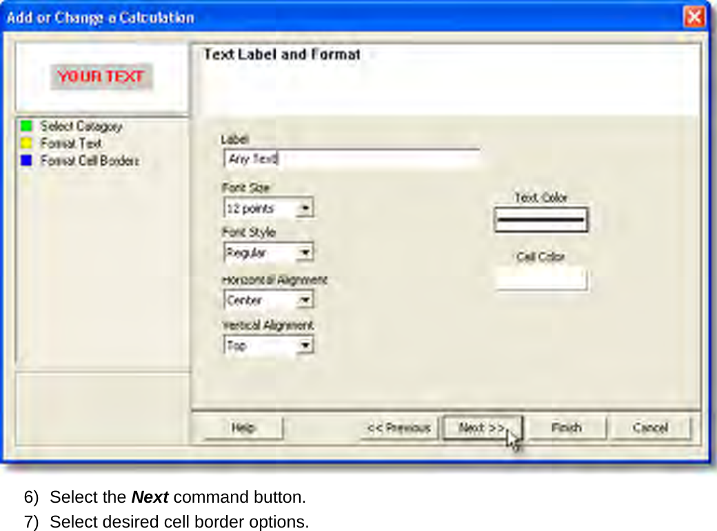
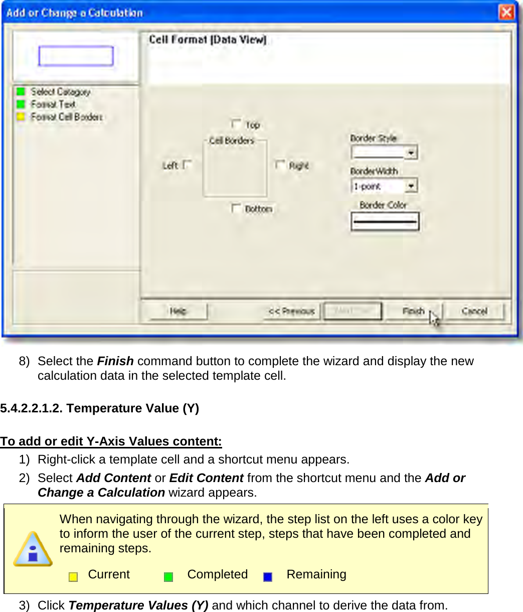
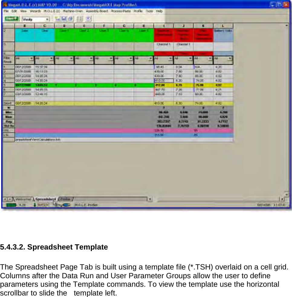
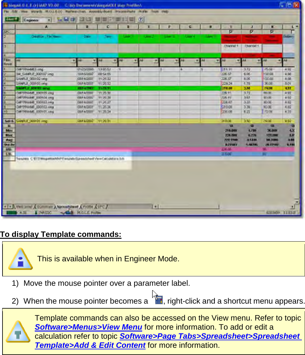
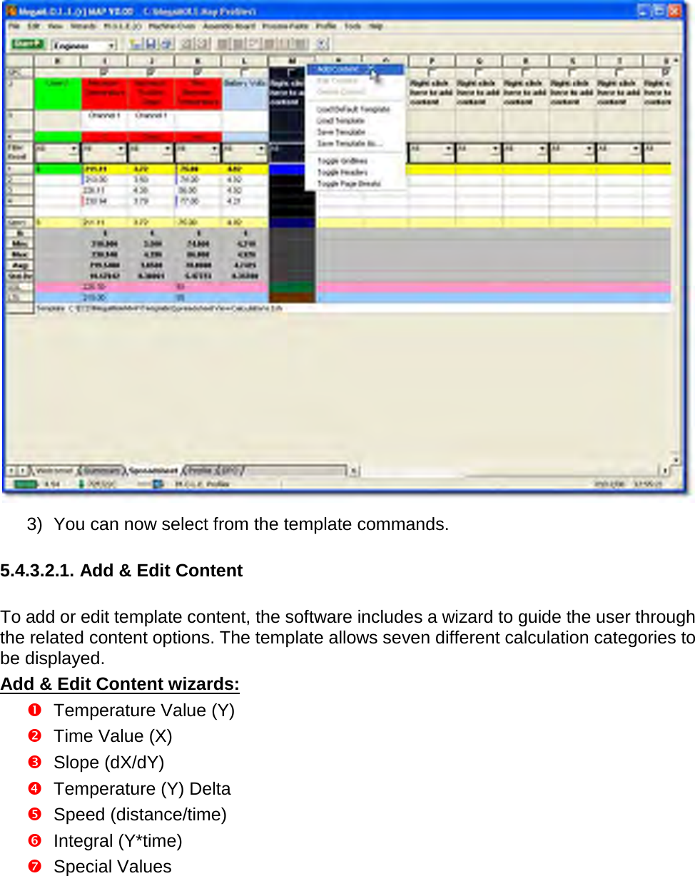
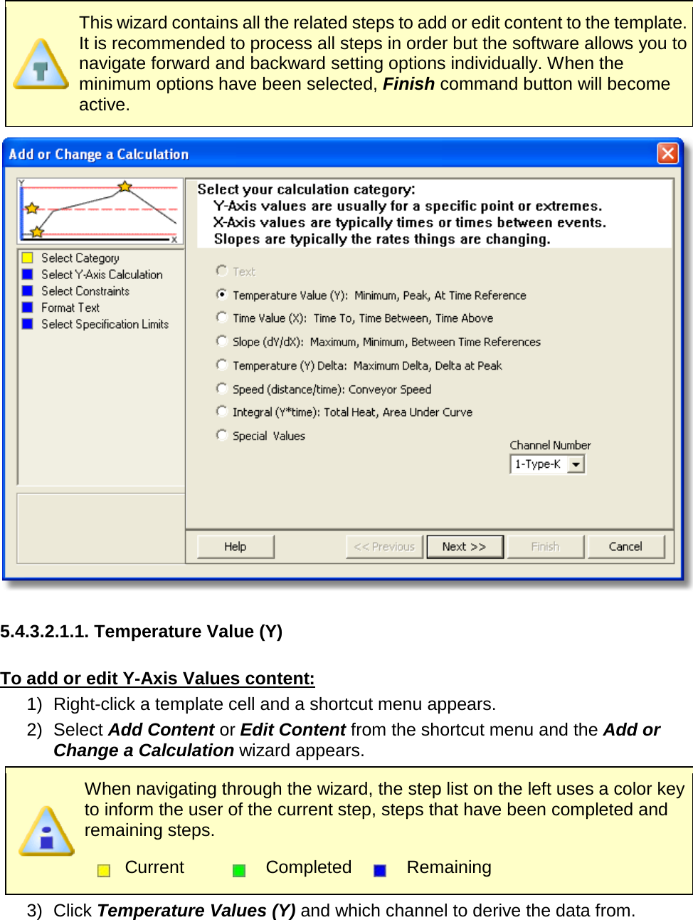
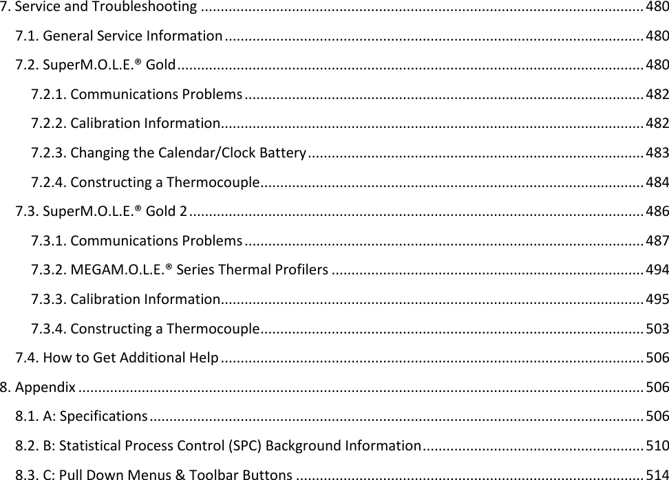
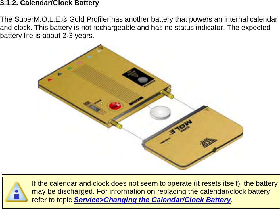
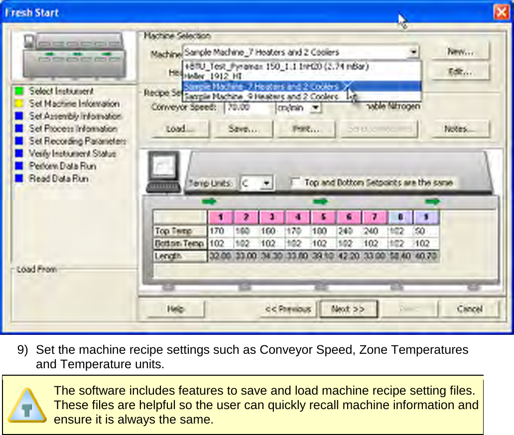
![5.4.1.3. Company/Report Name The text box located on the Welcome page tab allows the user enter a company or report name. To enter a name: 1) Using the mouse pointer, click in the text box. 2) Type a desired name and then hit the [enter] key to accept or [esc] to cancel.](https://usermanual.wiki/Electronic-Controls-Design/E51-0386-40.User-Manual-part-1-of-3/User-Guide-1481865-Page-120.png)