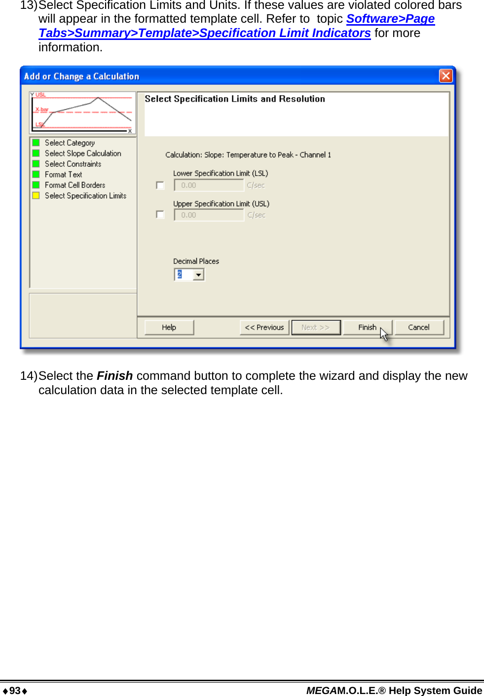
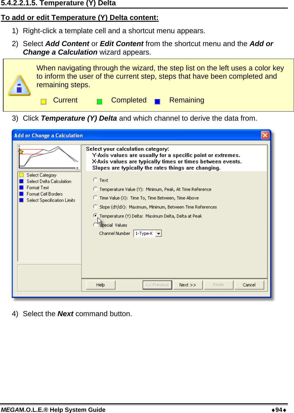
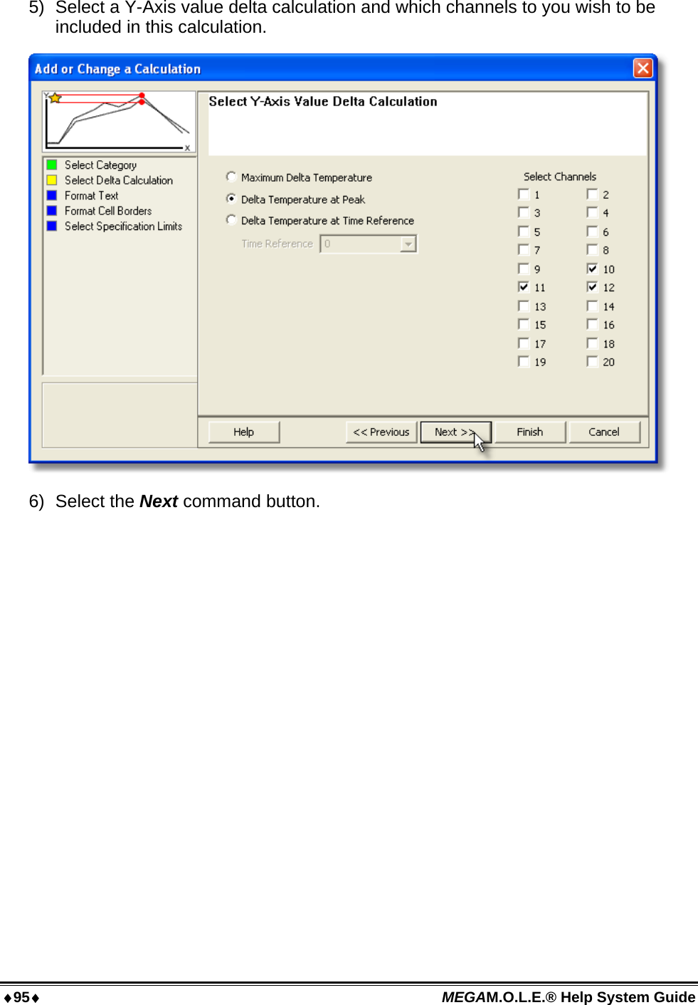
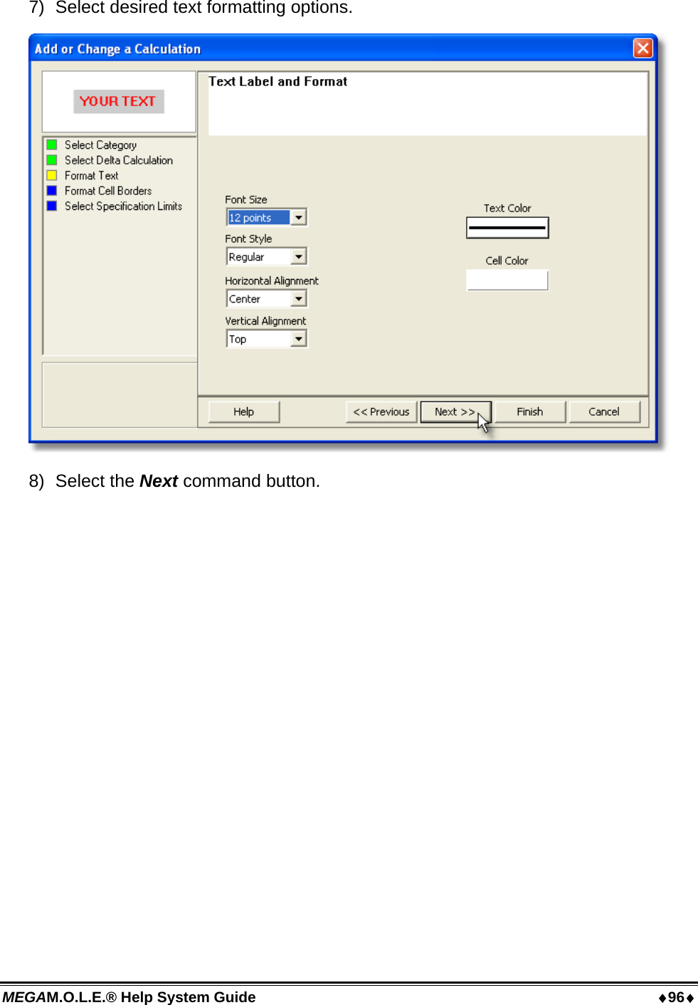
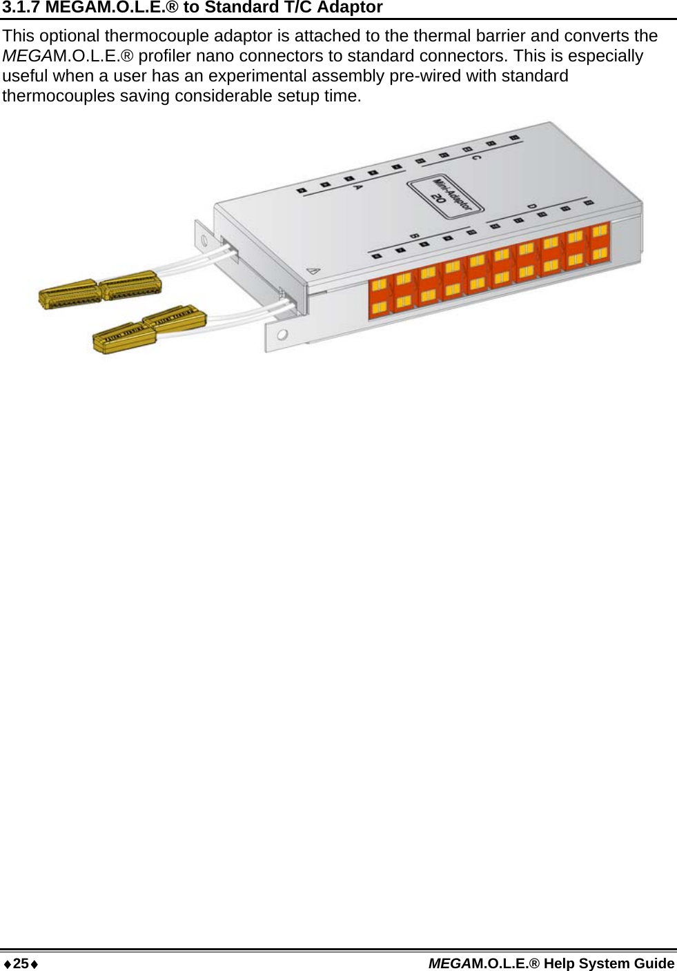
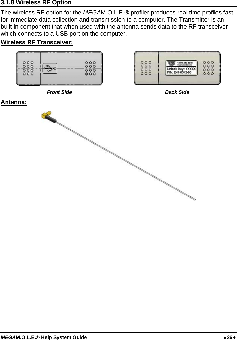
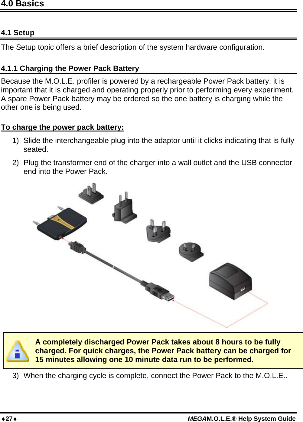
Electronic Controls Design E47-6342-45 MEGA M.O.L.E. User Manual A47 6342 00 2 10
Electronic Controls Design Inc MEGA M.O.L.E. A47 6342 00 2 10
Contents
- 1. Quick Reference Guide
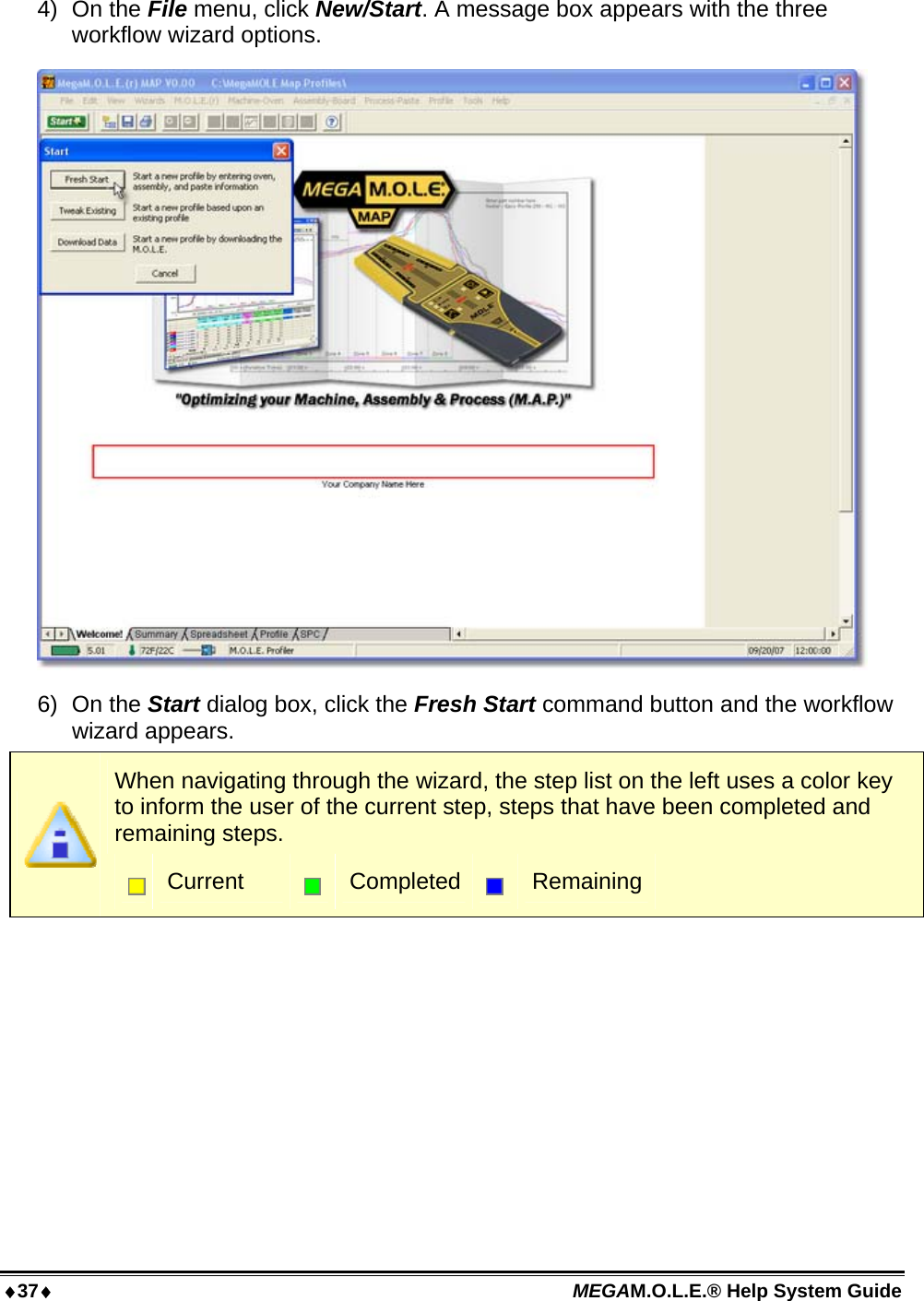
- 2. User Manual part 1
- 3. User Manual part 2
- 4. User Manual part 3
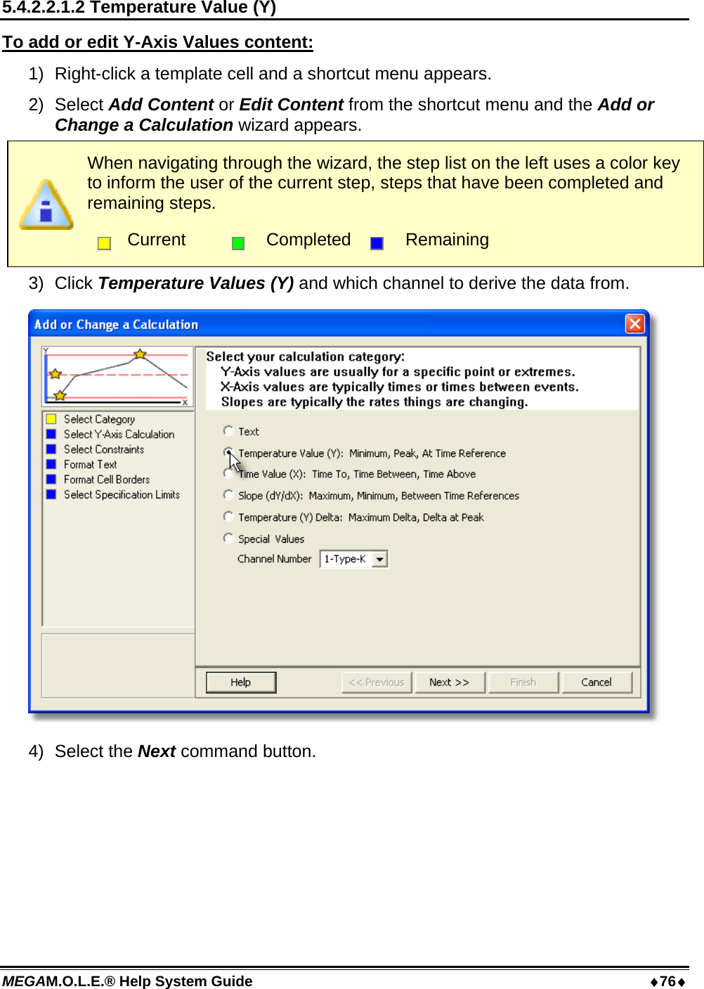
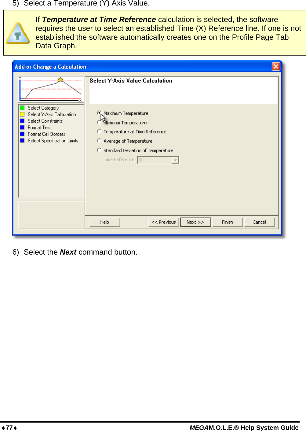
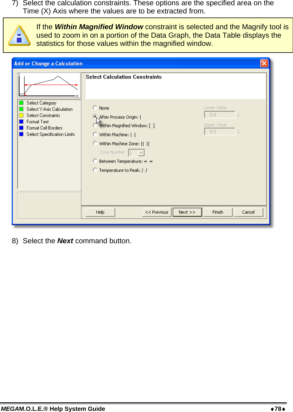
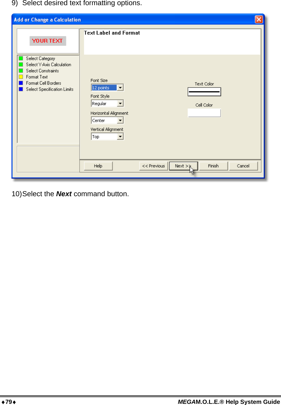
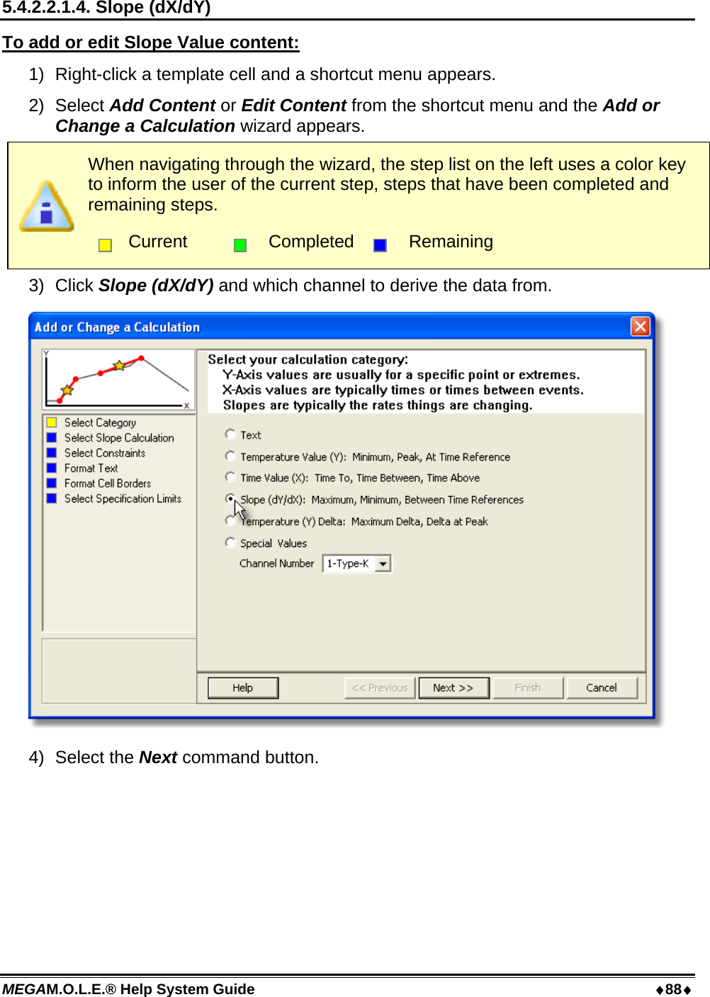
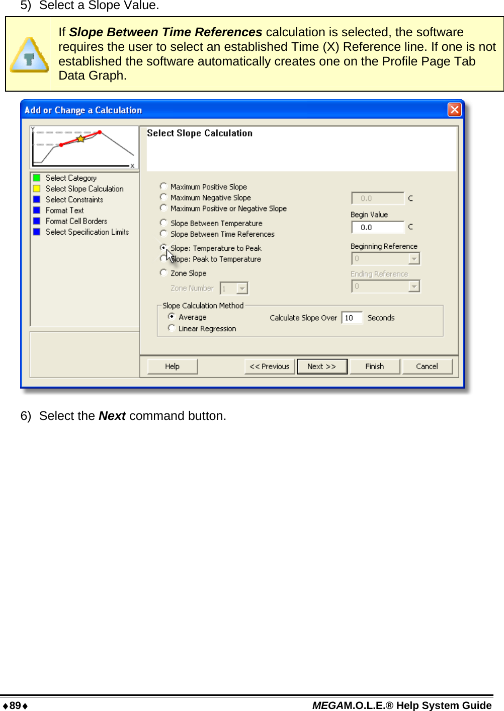
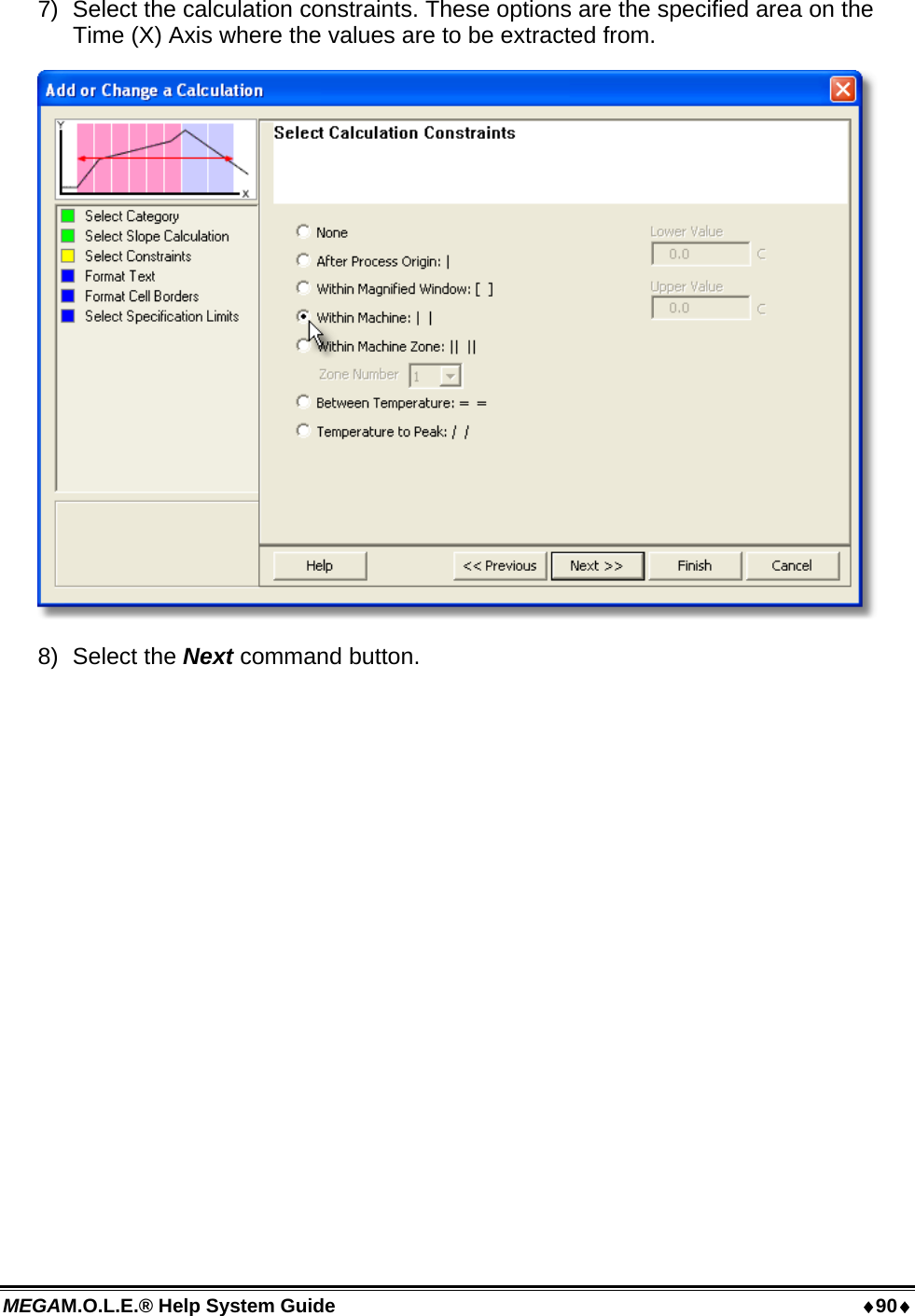
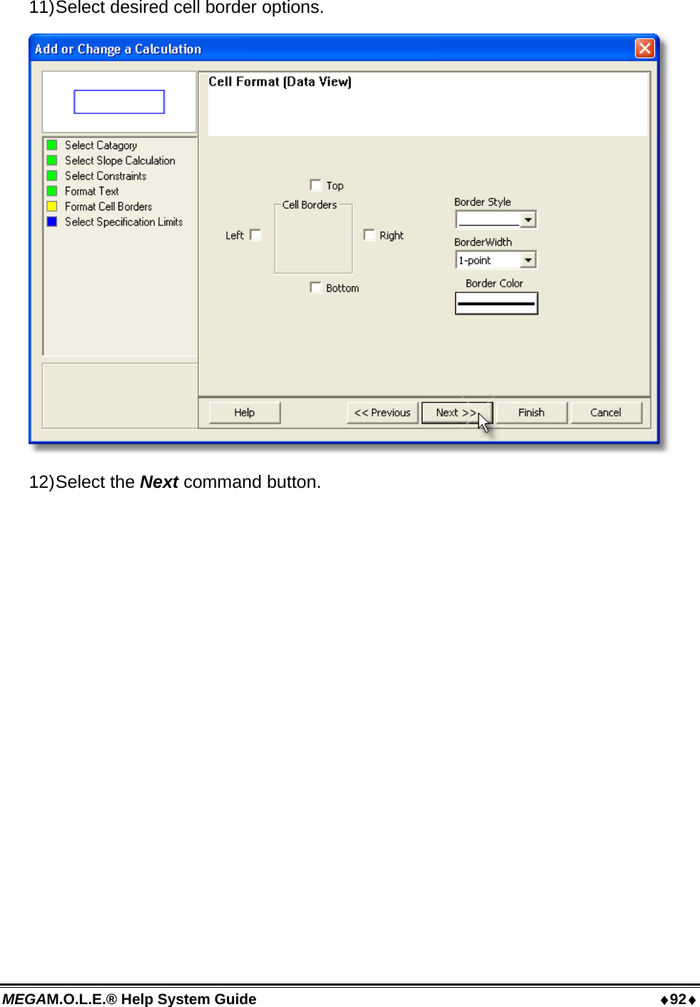
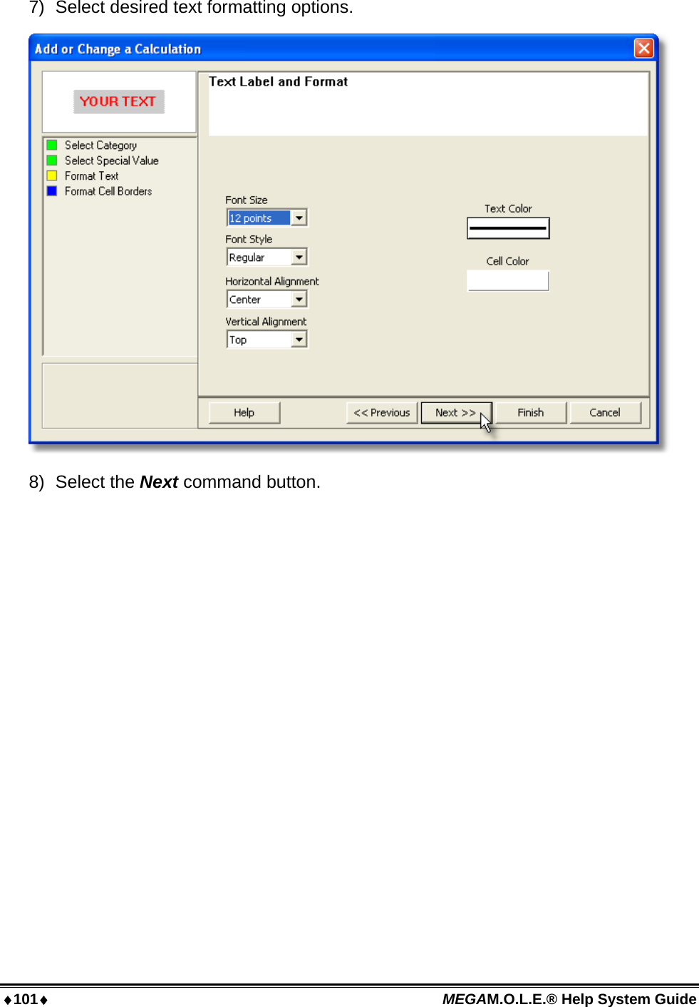
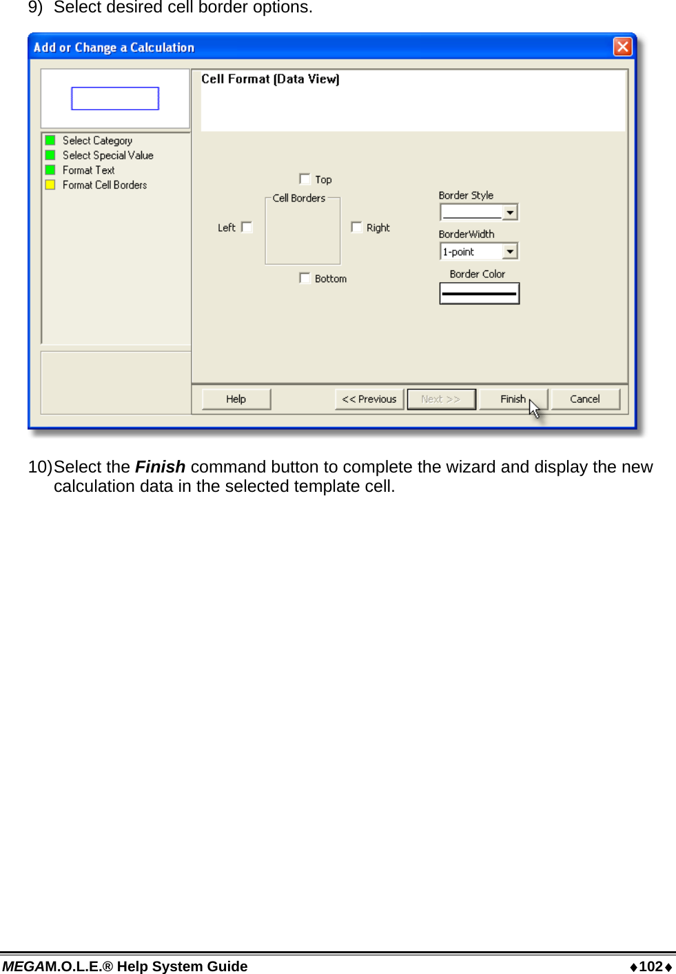
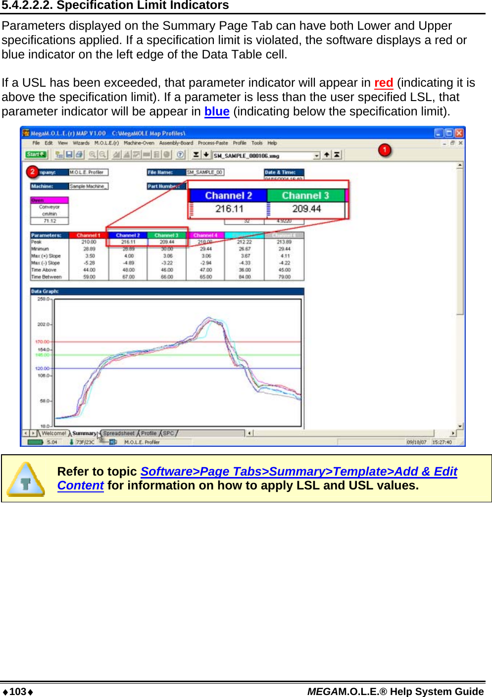
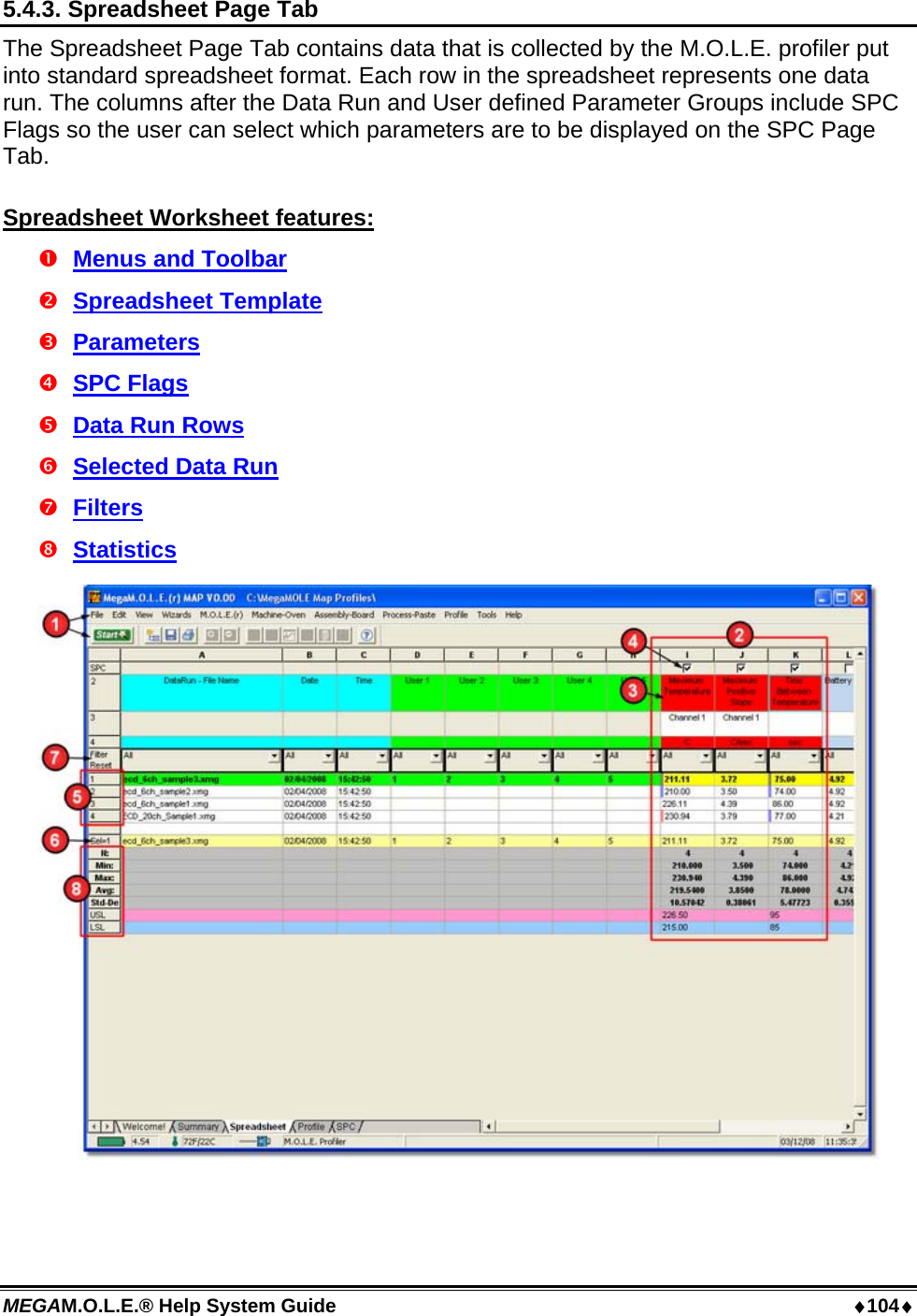
User Manual part 1
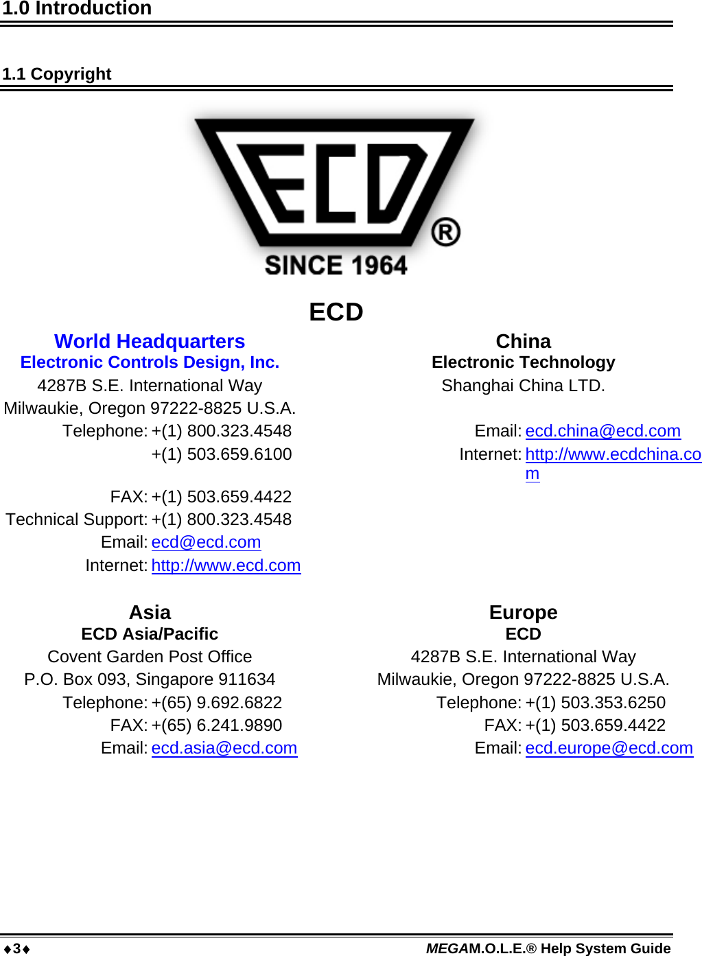
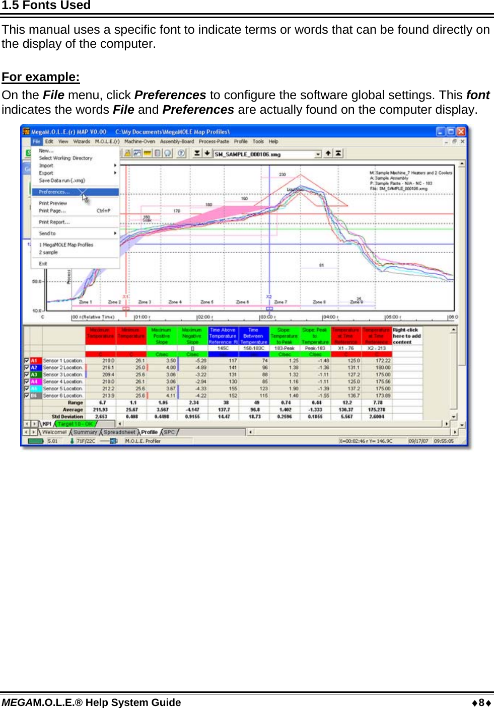

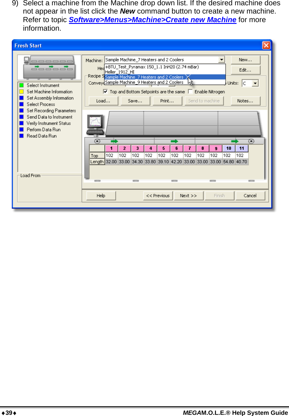

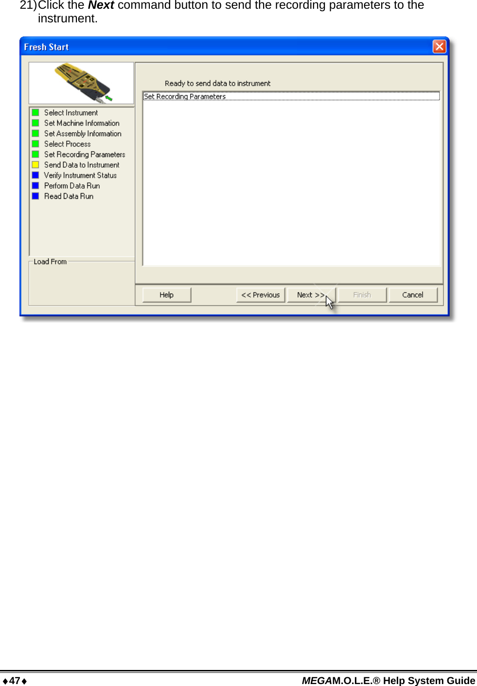

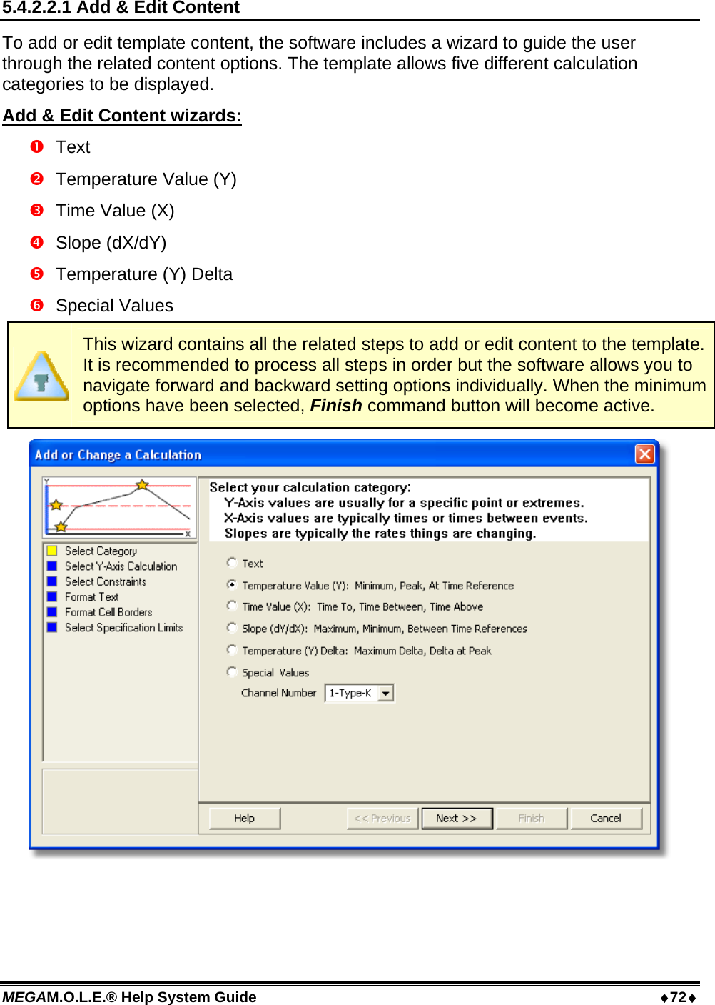
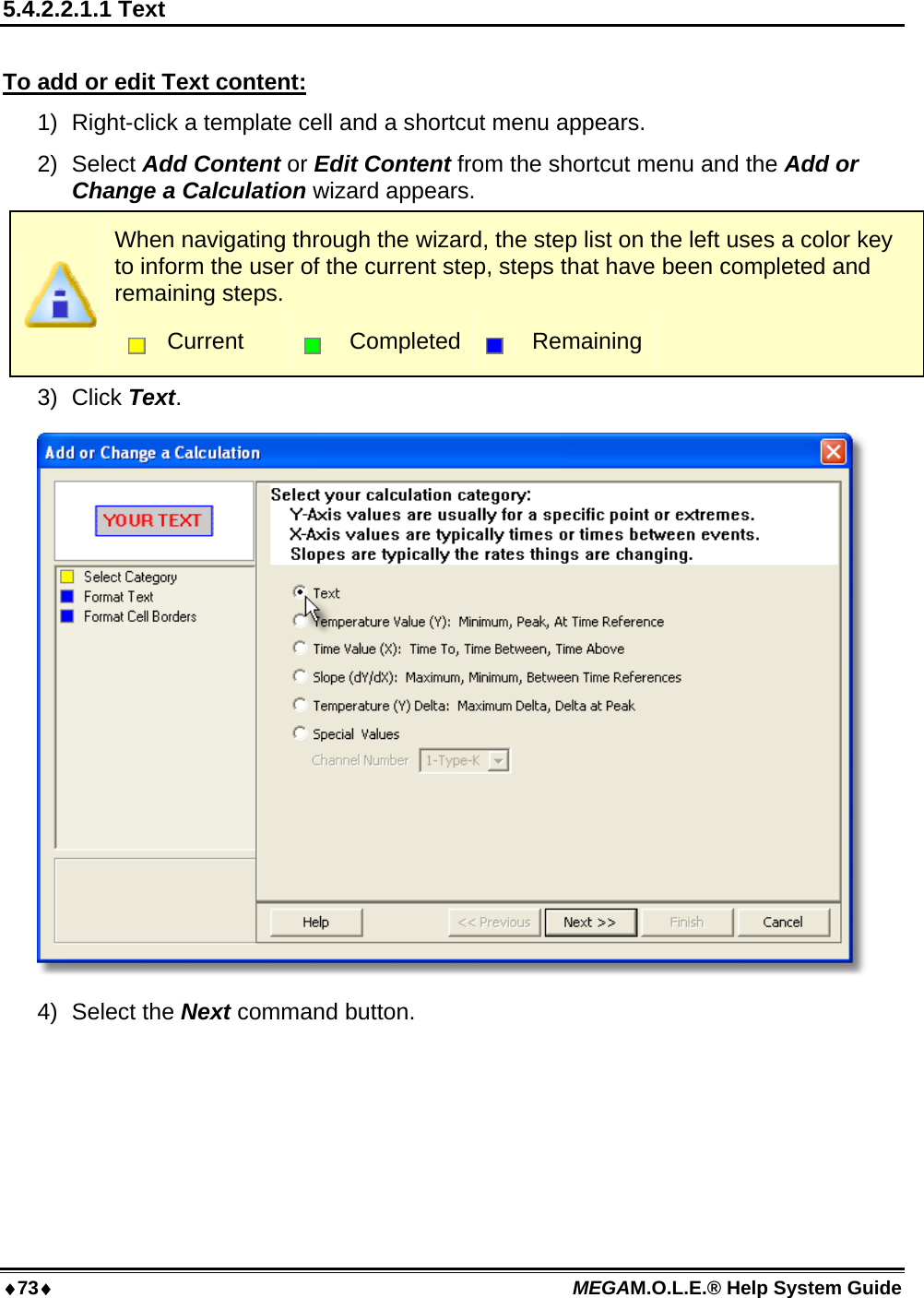
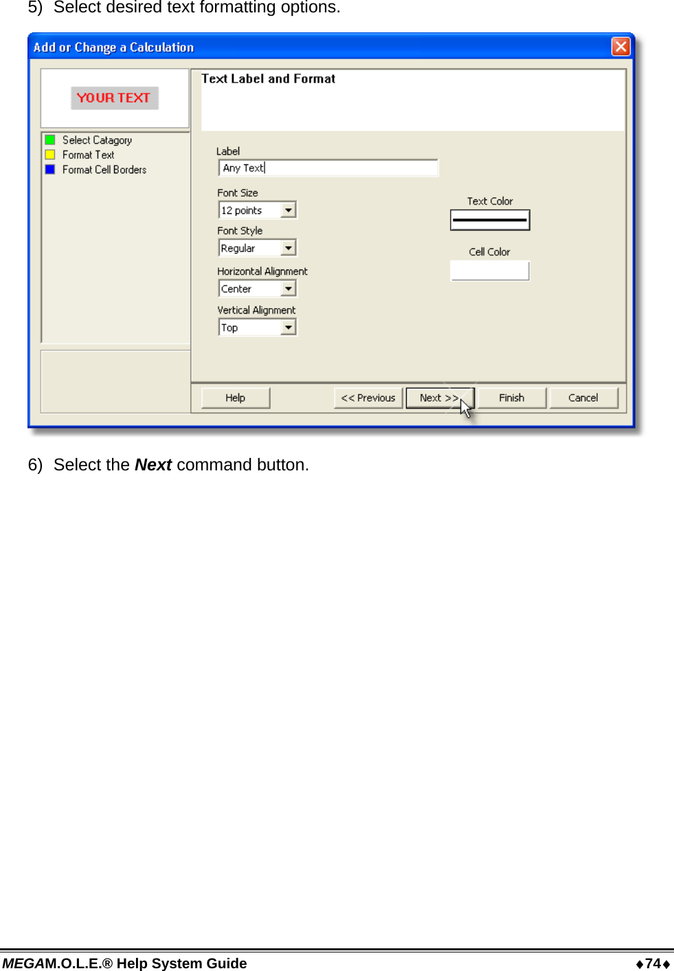
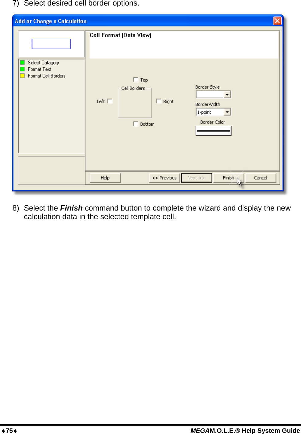
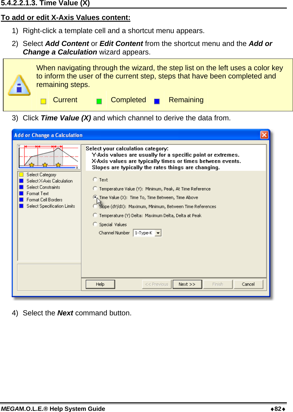
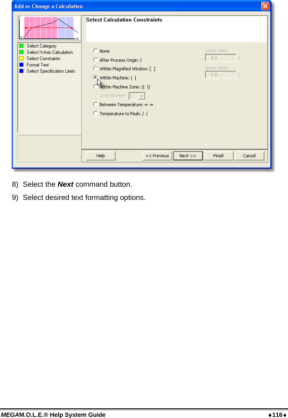
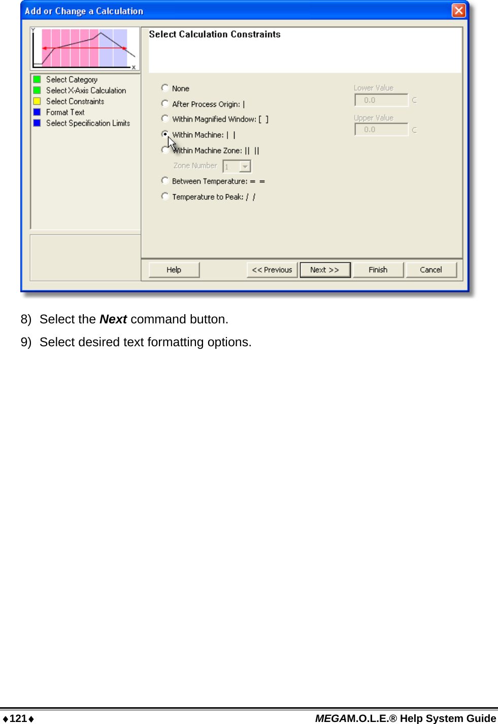
![MEGAM.O.L.E.® Help System Guide 62 5.3.3 Status Bar This bar is located on the bottom of the software display. It shows the status of the M.O.L.E. Profiler Power Pack battery, Internal operating temperature, connected COM port, available Help information, mouse pointer X-Y position, current date and time. Using the Preferences command, the user can decide which M.O.L.E. Profiler status bar items will be displayed. Refer to topic Software>Menus>File>Preferences>M.O.L.E. for more information. Battery: This indicator displays the voltage reported by the currently selected M.O.L.E. Profiler. The nominal range for normal MEGAM.O.L.E. profiler 4.0V to 3.0V. Temperature: This indicator displays the internal operating temperature reported by the currently selected M.O.L.E. Profiler. If the internal operating temperature is within the acceptable range (0°-40°C [0°-104°F]) the symbol appears in GREEN. When the internal operating temperature is above the acceptable range (41°C> [105.8°F>]), it appears in RED indicating that the M.O.L.E. profiler has reached the temperature warning zone.](https://usermanual.wiki/Electronic-Controls-Design/E47-6342-45.User-Manual-part-1/User-Guide-937649-Page-63.png)
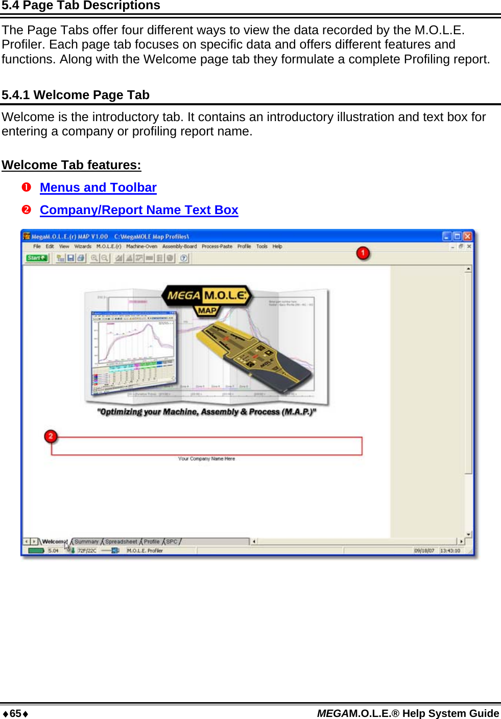
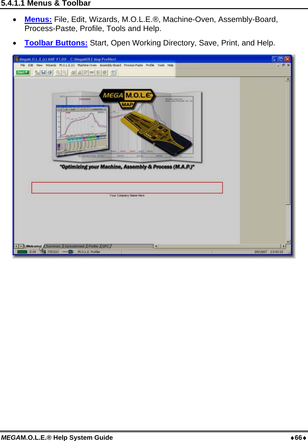
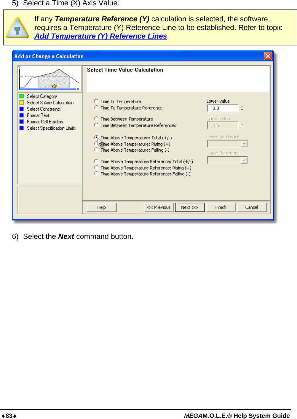
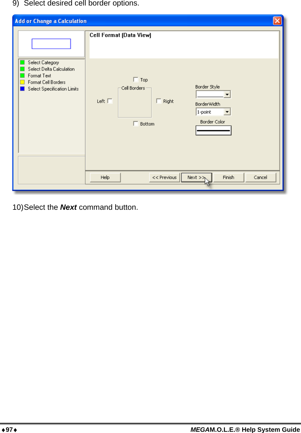
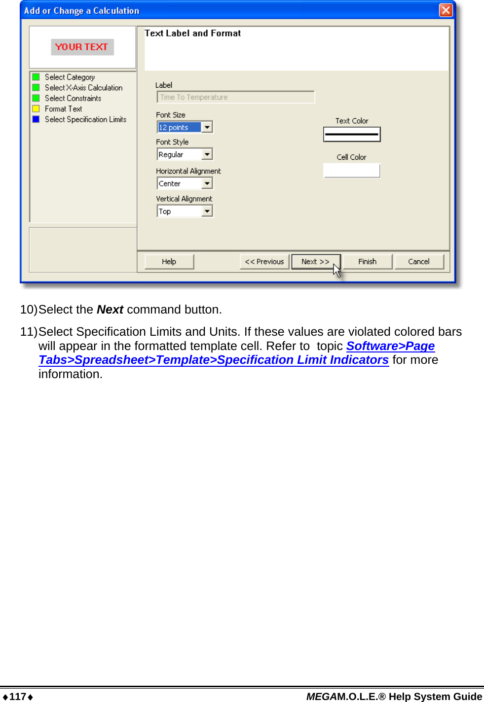
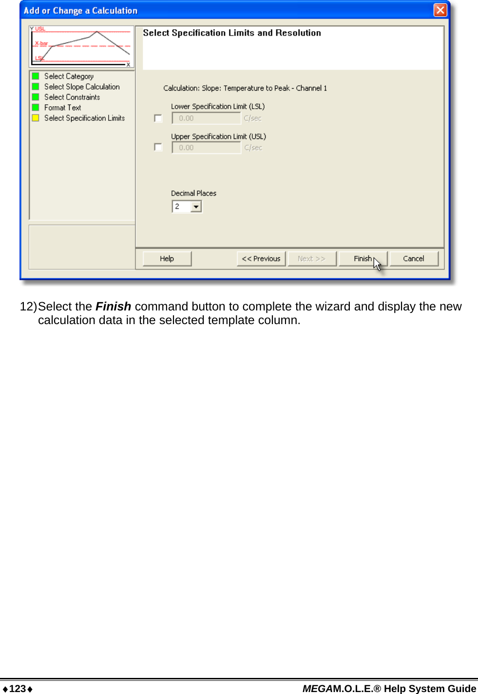
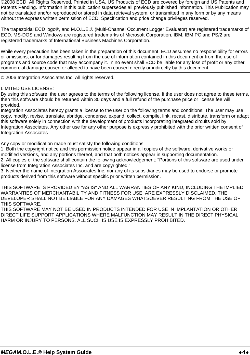
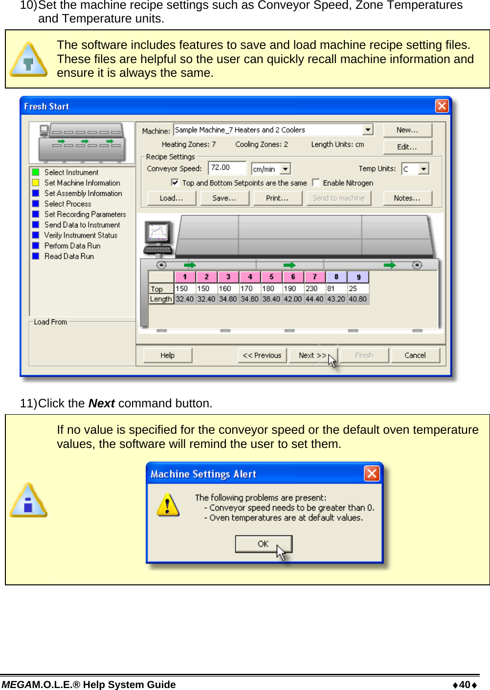
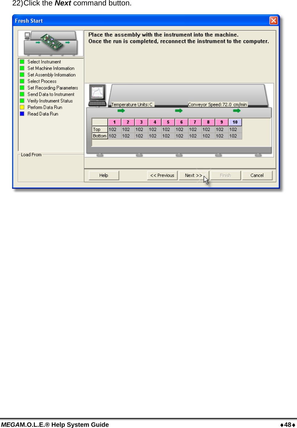
![67 MEGAM.O.L.E.® Help System Guide 5.4.1.2 Company/Report Name The text box located on the bottom half of the Welcome page tab allows the user enter a company or report name. To enter a name: 1) Using the mouse pointer, click in the text box. 2) Type a desired name and then hit the [enter] key to accept or [esc] to cancel.](https://usermanual.wiki/Electronic-Controls-Design/E47-6342-45.User-Manual-part-1/User-Guide-937649-Page-68.png)