EZ Automation EAS CAP/EAS Encoder-Decoder User Manual EZ EAS Manual
EZ Automation CAP/EAS Encoder-Decoder EZ EAS Manual
UserManual.wiki
>
EZ Automation
>
EAS User Manual
Draft Copy of User Manual
Navigation menu
Upload a User Manual
Namespaces
Wiki Guide
HTML
PDF
Info
Views
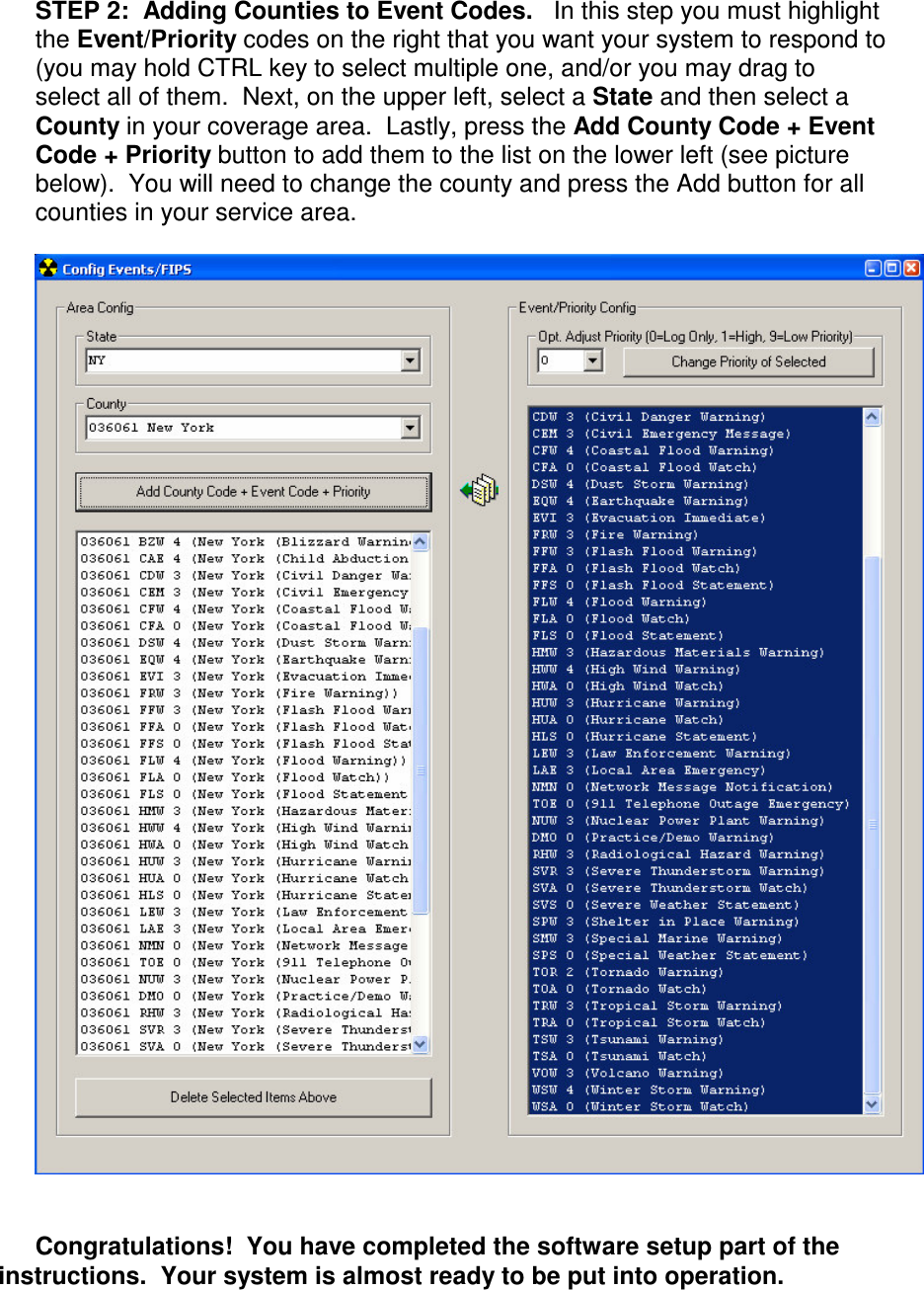
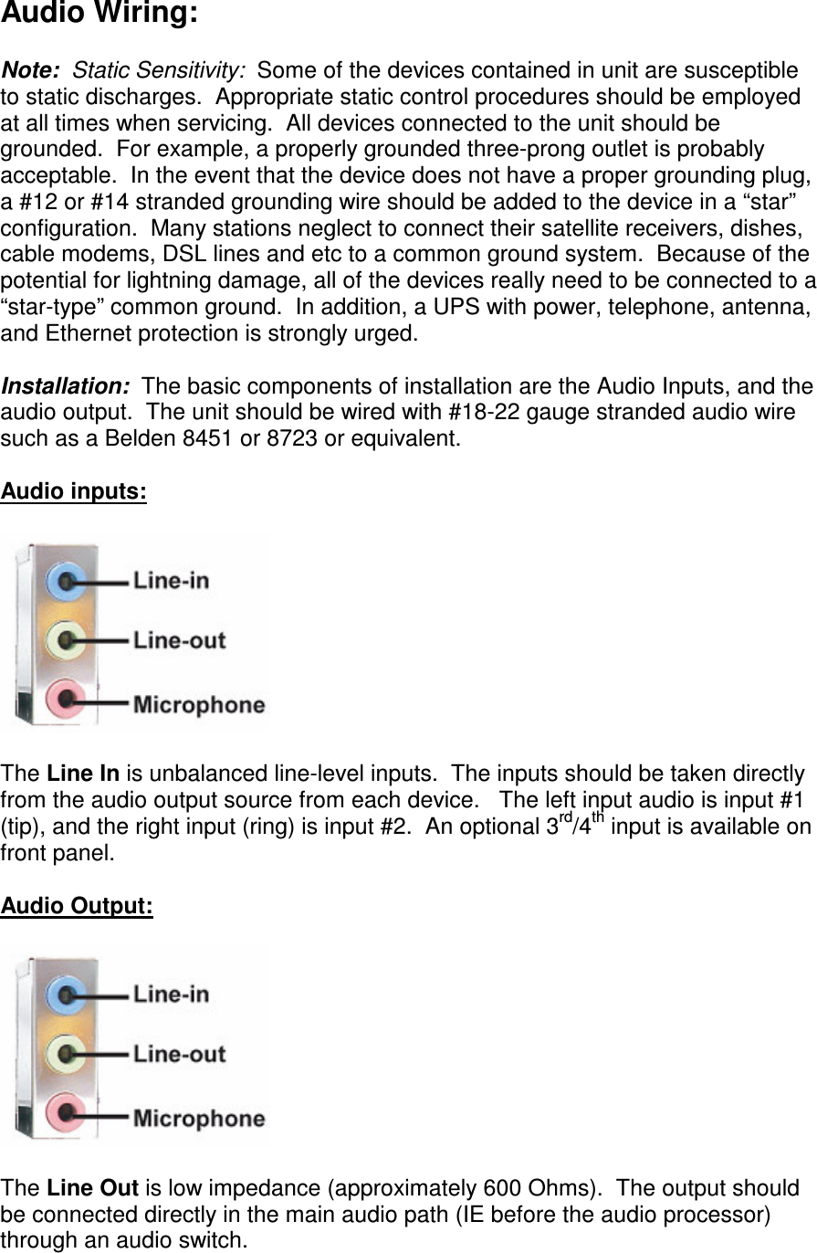
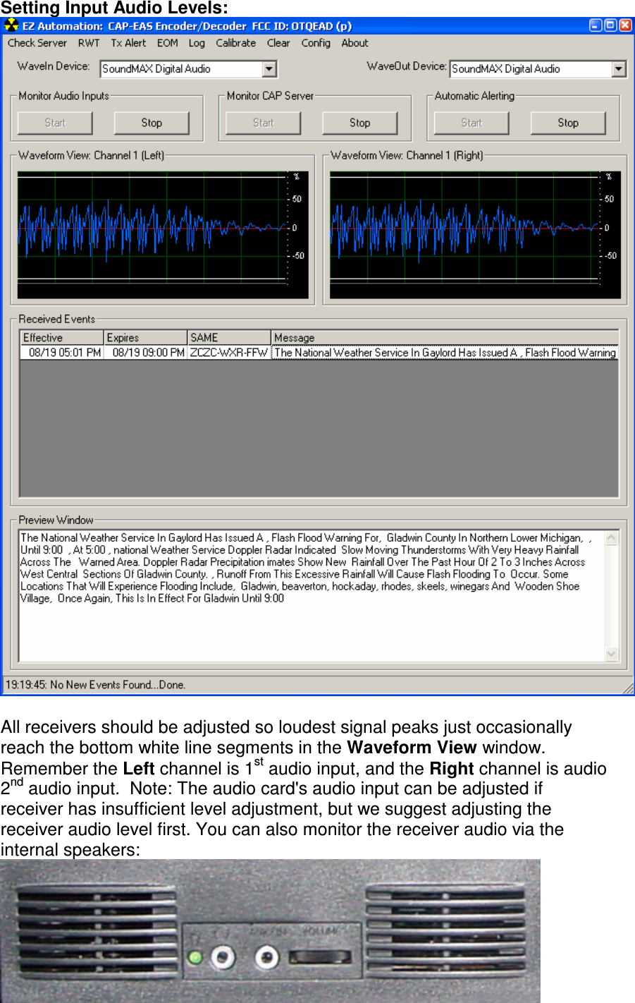
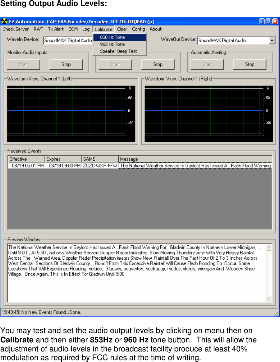
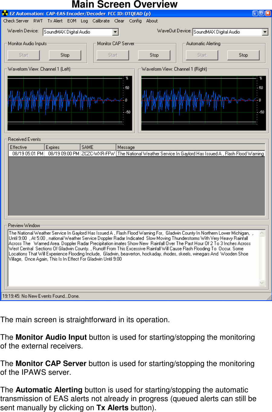
User Manual
Discussion / Help
Navigation