EMW BHA-WN400 Binary CDMA Compliant User Manual
EMW Co., Ltd. Binary CDMA Compliant
UserManual.wiki
>
EMW
>
BHA WN400 User Manual
User Manual
Navigation menu
Upload a User Manual
Namespaces
Wiki Guide
HTML
PDF
Info
Views
User Manual
Discussion / Help
Navigation
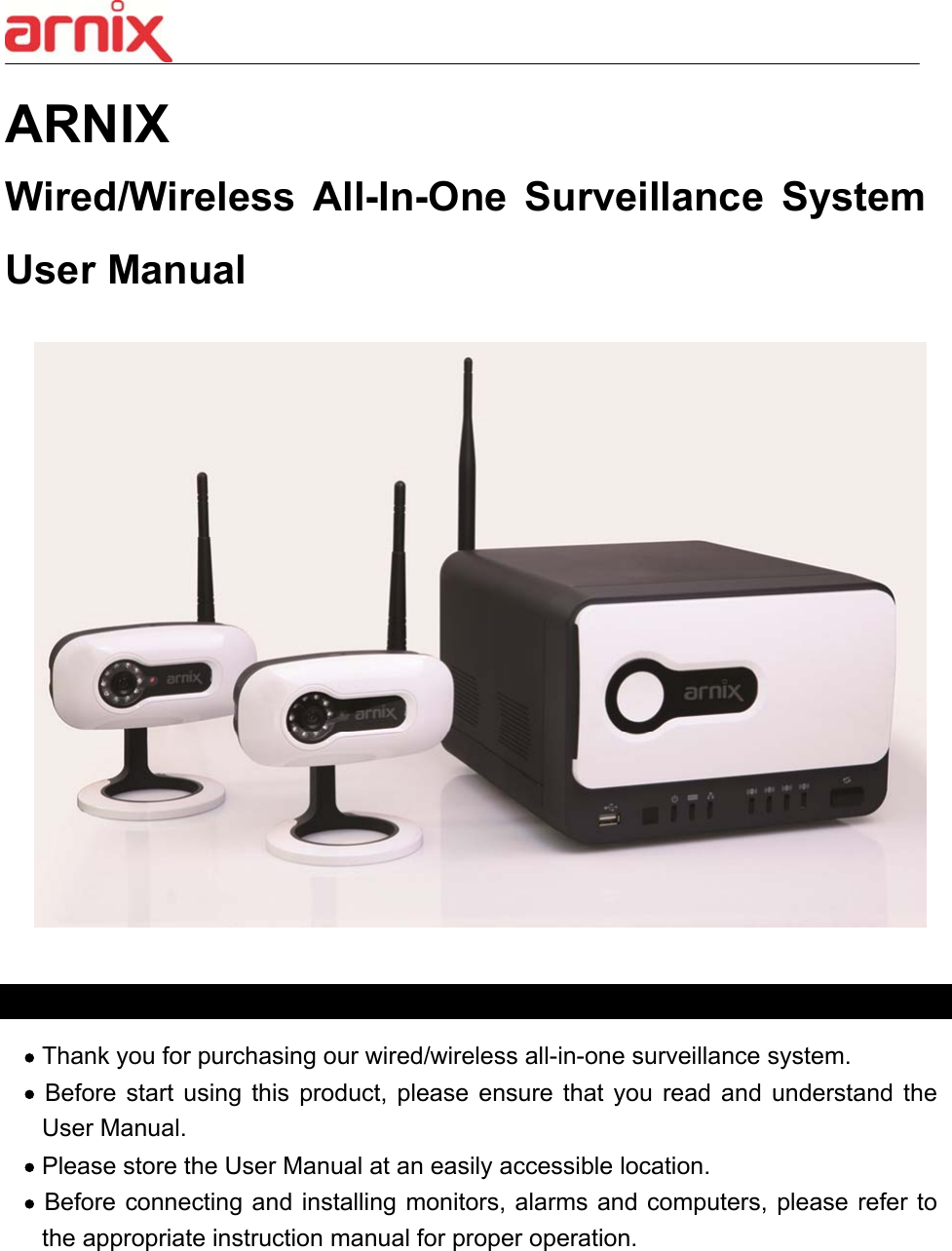

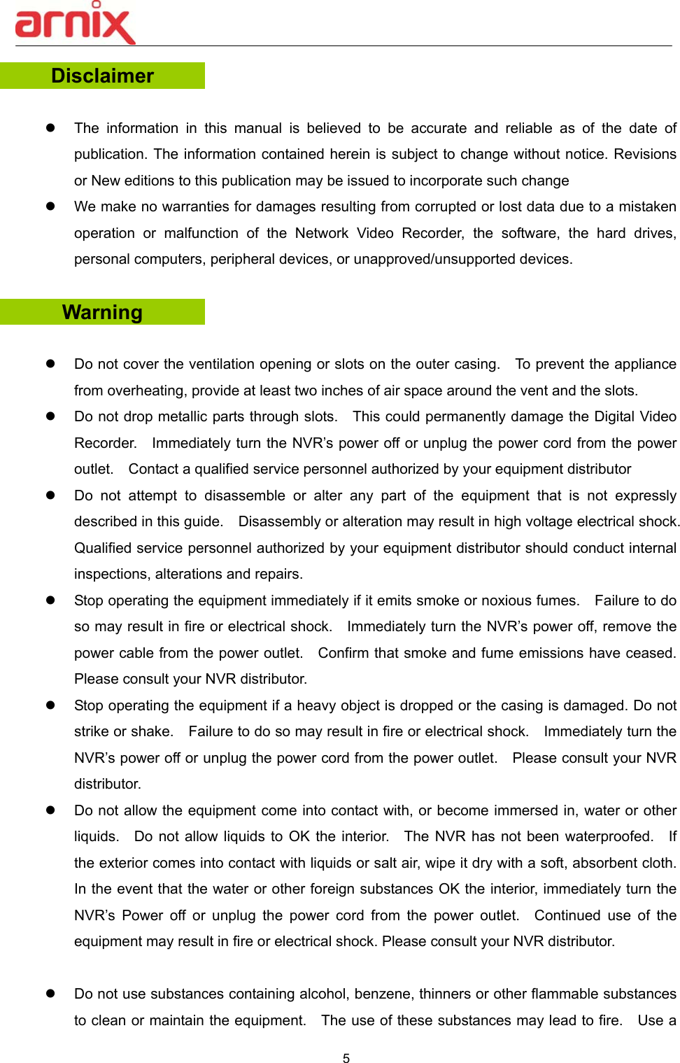
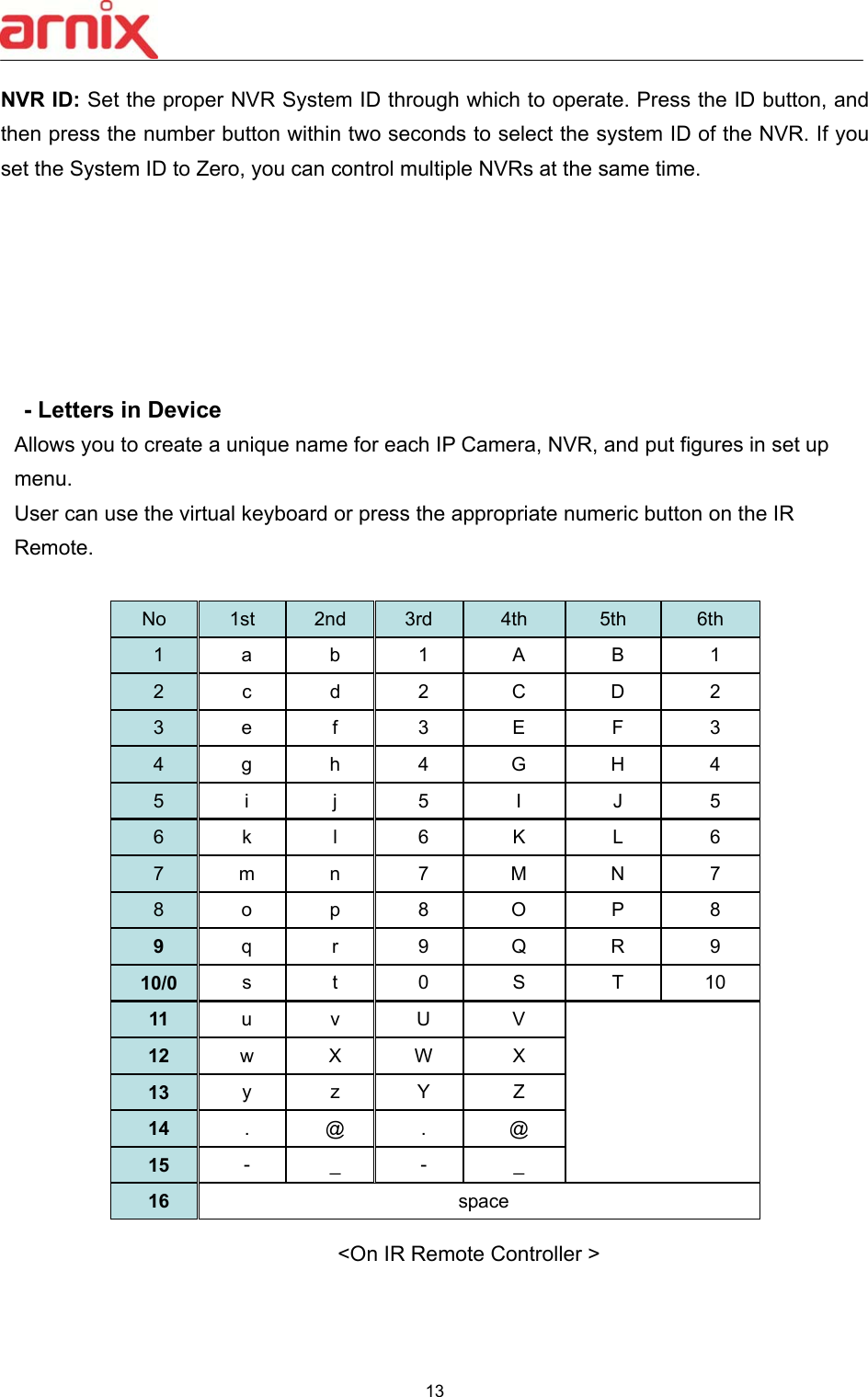
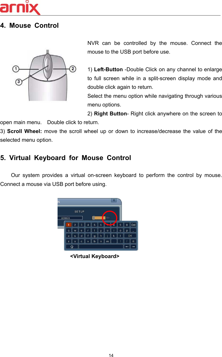
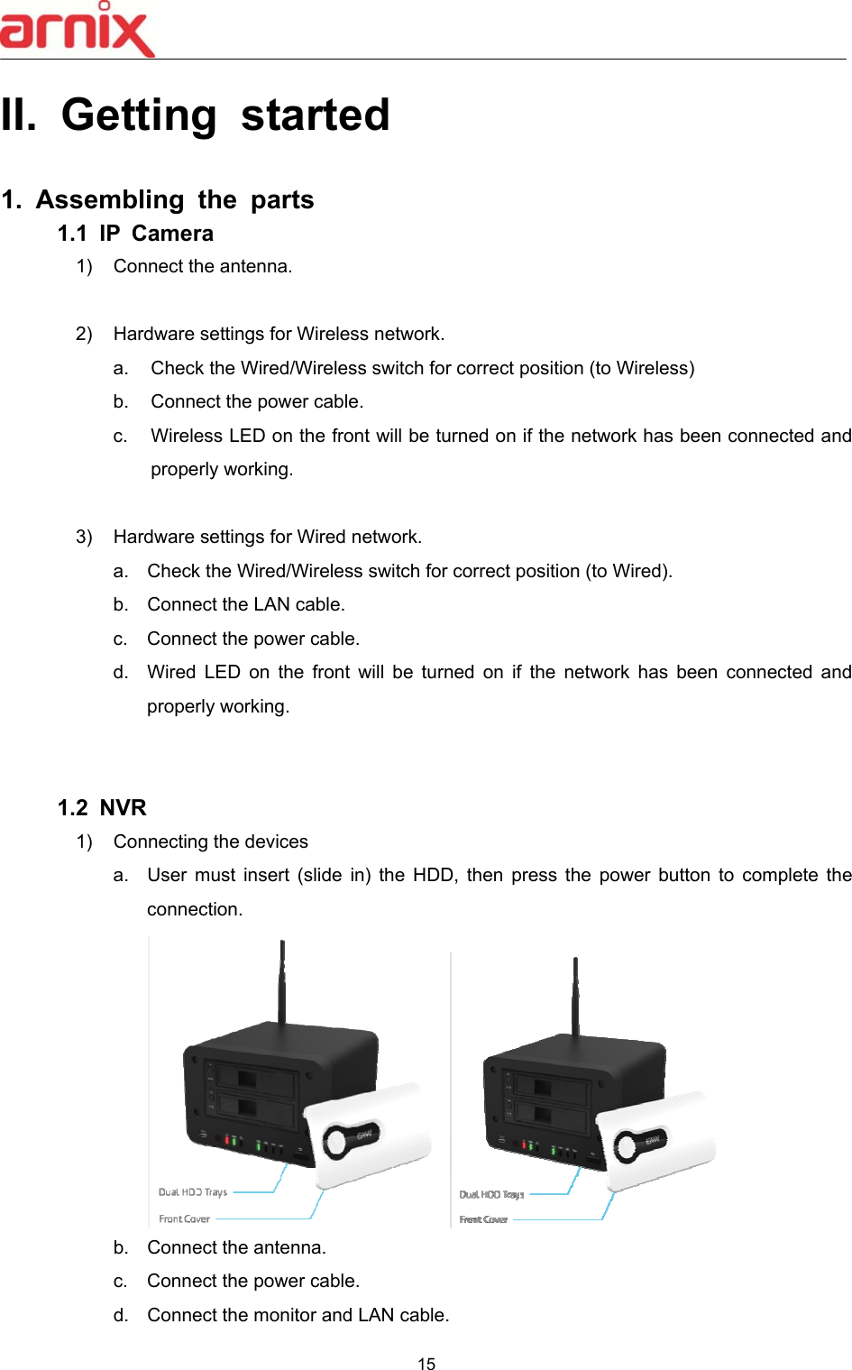
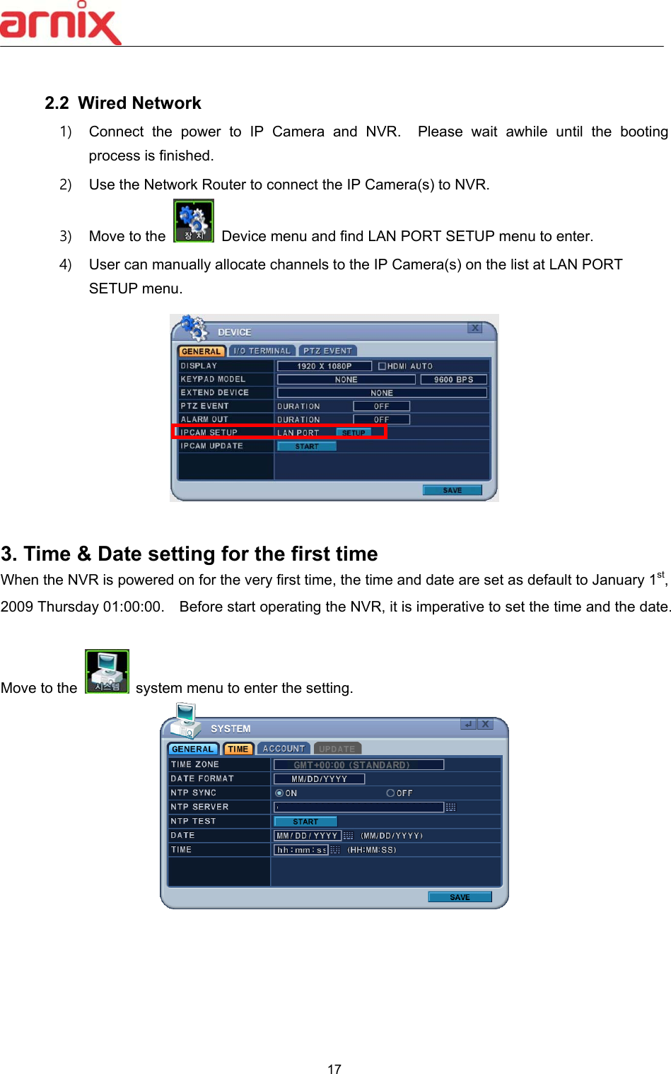
![16 2. Network Connection 2.1 Wireless Network 1) Connect the power to IP Camera and NVR. Please wait awhile until the booting process is finished. 2) Push the pairing button on the front panel of NVR for more than 3 seconds to establish the wireless network. Wait until the LED on the front panel changes from blinking red to green. <Caution> Pairing sequence must take place if you are connecting the IP Cameras to NVR for the first time. 3) After finishing the wireless network setting, user must allocate the channels to the IP Camera(s). Find Wireless icon on the main menu, then enter the menu to select the IP Camera(s) from the list. User can either allocate channels to the IP Camera(s) automatically by pushing [Auto Link] button, or allocate the channels manually.](https://usermanual.wiki/EMW/BHA-WN400/User-Guide-2256800-Page-17.png)
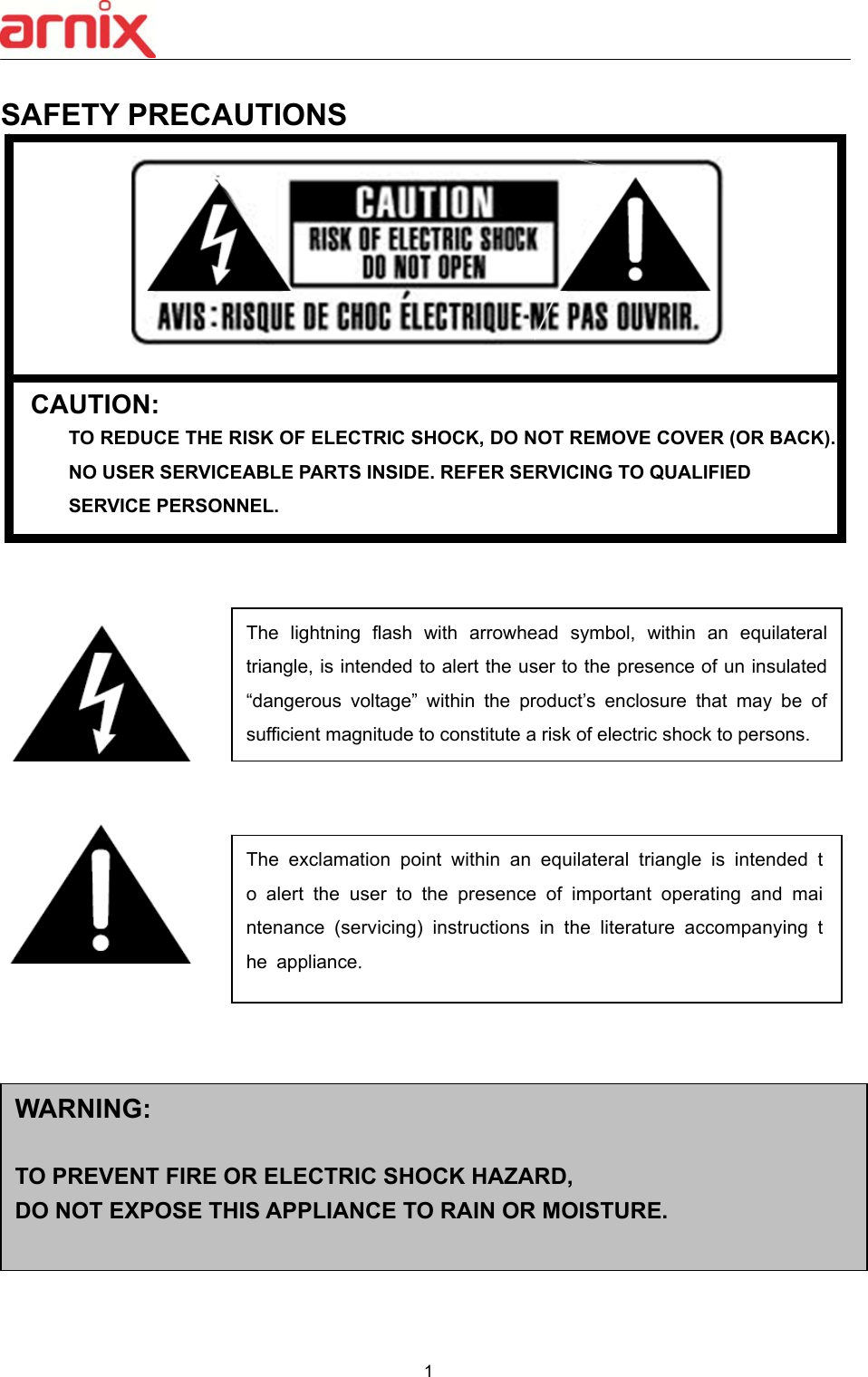
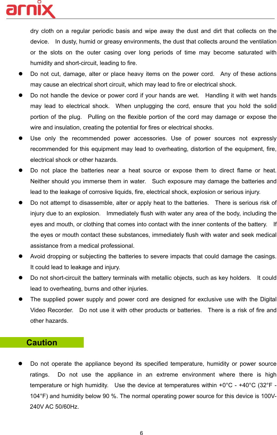
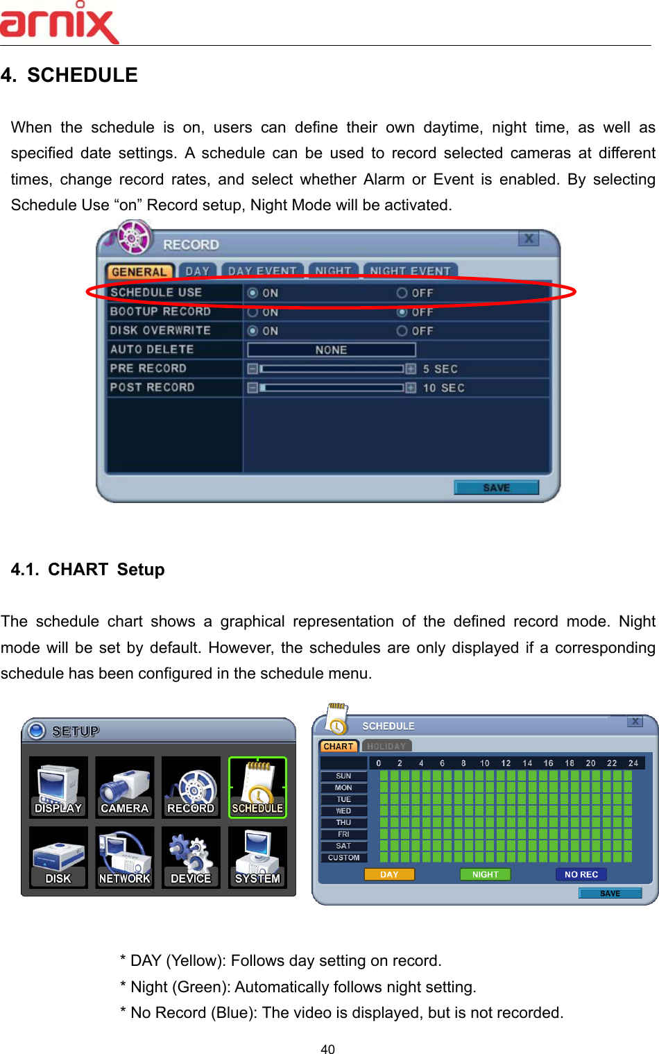
![18 Log in ID is set to "admin" as default and the password is set to “000000” as default. Main menu can be entered into by pushing [MENU] button on the remote controller or by clicking right button on the mouse. Setup Time Search External Search Power Zoom System info.Playback Log Display Backup Wireless](https://usermanual.wiki/EMW/BHA-WN400/User-Guide-2256800-Page-19.png)
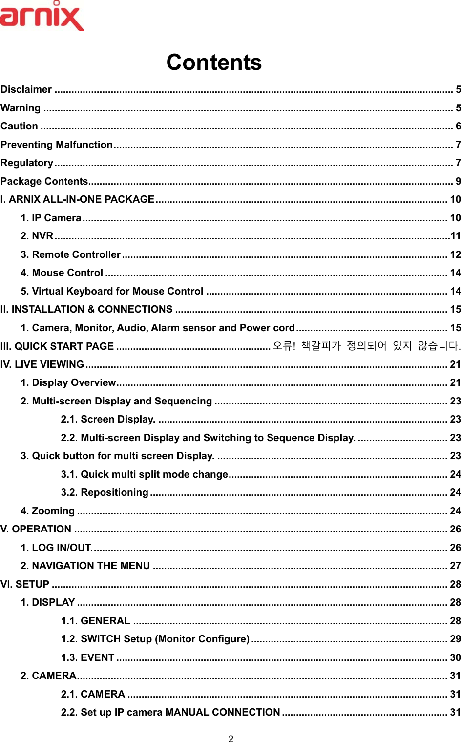
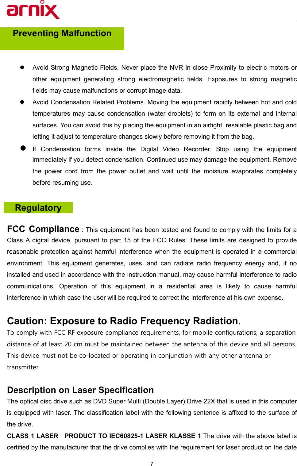
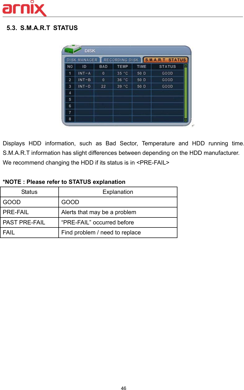
![19 4. Recording 4.1 Formatting the HDD (In case of initial HDD installation) Move to the DISC manager menu (Main menu SETUP DISC). ① Use Up/Down, Left/Right [,] buttons to select the device and use [-, +] buttons to select the proper options. ② In order to start the recording, HDD must be formatted (old data on the HDD will be lost by formatting). ③ User is set for recording once the formatting process is done. 4.2 Recording method User can immediately start recording by pressing the [REC] button. Move to the Recording menu (Main menu SETUP Recording) for advanced settings. <Note> Please refer to the Recording section on the manual for advanced settings.](https://usermanual.wiki/EMW/BHA-WN400/User-Guide-2256800-Page-20.png)
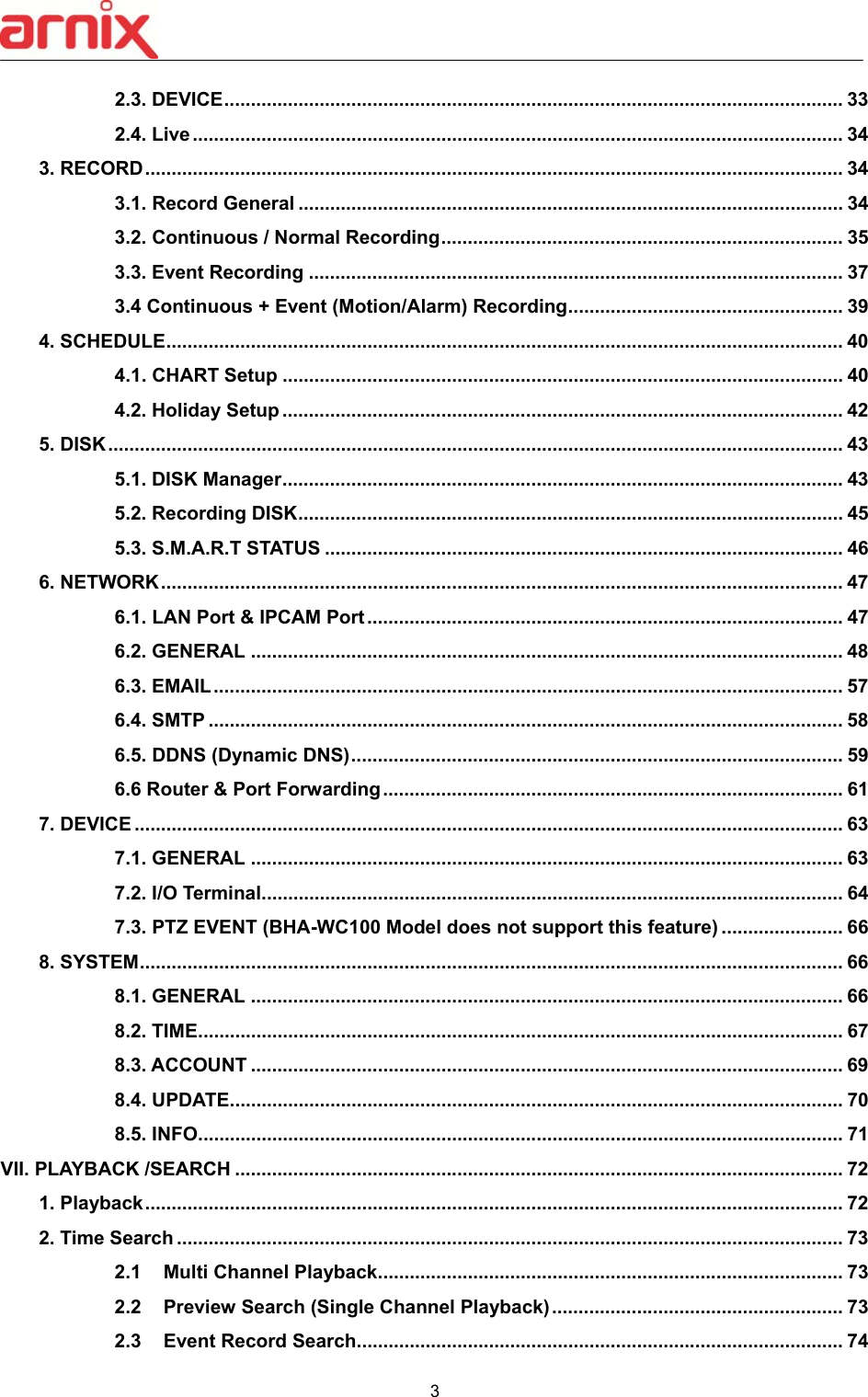
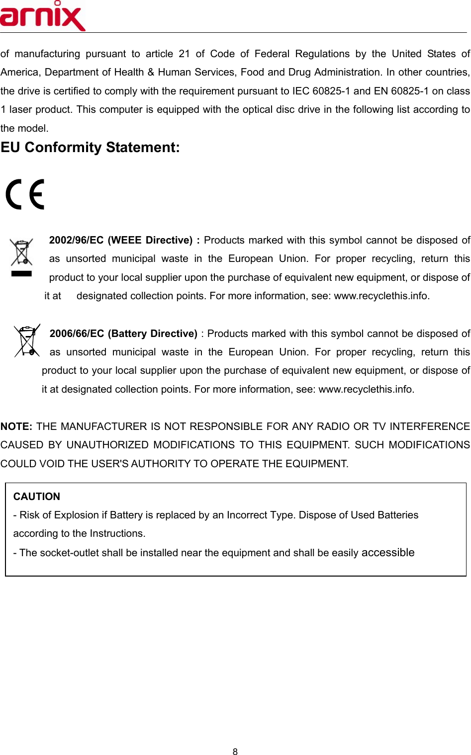
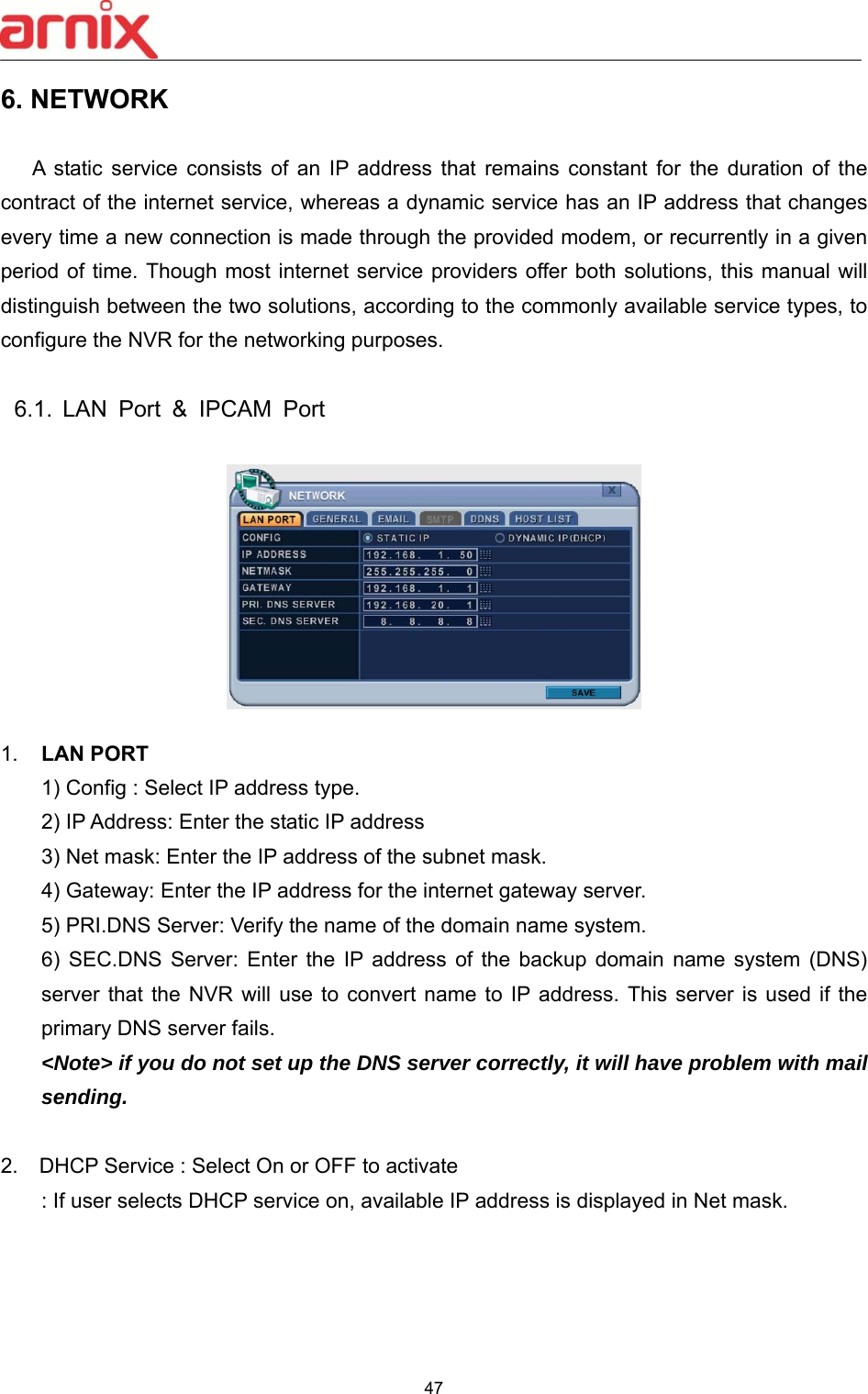
![20 5. Playback 5.1 Playback method User can play the most recently recorded data by pressing [Play] button. User can also play the recorded data by pressing [Time Search] button. User can also reach the Playback mode through [Time Search] menu and [Playback] menu on the Main menu.](https://usermanual.wiki/EMW/BHA-WN400/User-Guide-2256800-Page-21.png)
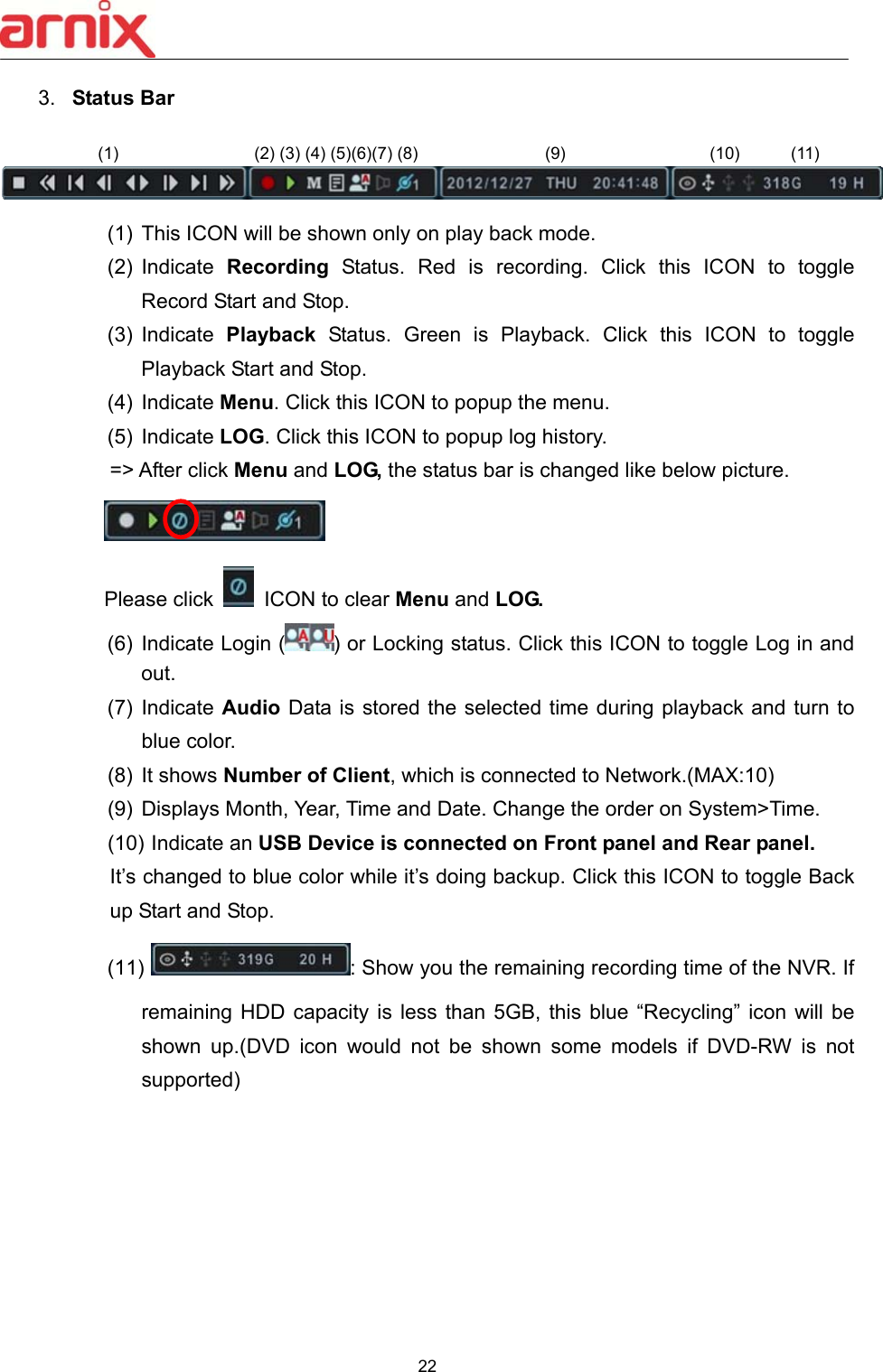
![21 III. LIVE VIEWING 1. Display Overview 1. Recording Mode Background color of Number will be different based on the recording status. 1) Red - Event (Motion/Alarm) Recording 2) Yellow - Continuous Recording 3) Black - No Recording. 2. Event Indicator (1) Indicate Alarm In terminal is triggered by an alarm sensor. To appear Alarm window, press [UP] button. This button toggles between Shows or Hide the Alarm Window. (2) Indicate Motion detected. To disappear, press [ESC] button. (3) Indicate Video Loss during Recording. To disappear, press [ESC] button. (1) (2) (3)](https://usermanual.wiki/EMW/BHA-WN400/User-Guide-2256800-Page-22.png)
![23 2. Multi-screen Display and Sequencing 2.1. Screen Display. Select any camera for Full screen display by pressing the Number button of the desired camera. For 12ch, press 1 and then 2. 2.2. Multi-screen Display and Switching to Sequence Display. 1) Press [DISPLAY] buttons to activate the multi screen display. It is changed in the order as shown below among your choice of SPLIT MODE. 2) To start Auto Sequence display, press [DISPLAY] buttons for 2 seconds and full screen sequencing will be started. Click this ICON by Mouse or SPOT OUT button on the remote control, you will see following virtual controller Main Monitor 3) The Auto sequence mode and dwell times are programmable in Switch set up. For detailed information about configuring those, see “Switch Setup”. If the sequence mode is not activated, it moves to Quad mode instead of Sequencing. 4) The Split mode is programmable in General set up. 3. Quick button for multi screen Display. SPLIT MODE In Auto Sequence Mode Push to activate Auto Sequence](https://usermanual.wiki/EMW/BHA-WN400/User-Guide-2256800-Page-24.png)
![24 3.1. Quick multi split mode change - Press F1 button on the remote controller + <Number> For example, press F1 button then number 4. The four channel view mode will be displayed. <Note> BHA-WP200 model supports only 4 channel display. 3.2. Repositioning It is possible to reposition the camera from a window to another window. ① Press F2 button on the remote controller. Mark will be displayed. ② Press Numeric button you wish to switching display. ③ Press [MENU] button to exit here with saving changes. Press [Cancel] to exit without change. Press [DISPLAY] button to rearrange. 4. Zooming](https://usermanual.wiki/EMW/BHA-WN400/User-Guide-2256800-Page-25.png)
![25 During live view mode, it is possible to zoom into a section of the screen to get a close-up view of the screen. 1. To activate the digital zoom, select the full screen display of the camera you wish to zoom. 2. Then press the [ZOOM] button on IR Remote controller. Zoom area box pops up, as shown below. 3. Move the box to the desired position using Direction [ ] buttons. 4. Press [+] button to enlarge the image. Press [ - ] button to zoom out the image. 5. Press [ESC] button to return normal mode. <Note> If the Zoom button is pressed while in a multi-screen display, zoom operation is not activated. x 2 x 4 x 8](https://usermanual.wiki/EMW/BHA-WN400/User-Guide-2256800-Page-26.png)
![26 IV. OPERATION 1. LOG IN/OUT. You must log on to the NVR with valid password to operate the NVR. By default, it comes with one login account; ADMIN and the default password is “000000”. <Note > If you are logging on for the first time, the system does not prompt you to change the default password. Therefore, it’s strongly recommended to change the “PASSWORD” when you install the NVR. Refer to [System Setup]. 1. Login 1) On the front panel or remote control, press the power button. 2) When the NVR is powered on, it will start to scan NVR status. 3) Live Viewing screen will appear after initialization about 50sec. It can be delayed when you have defect HDD, it will try to fix for logical problem but it will show you warning message for physical problem. 4) On the remote control, press Login. Using the mouse, click the login icon, login dialog box pops up. 5) Login Icon will be changed on status bar. 2. Logout On the remote control, press LOGIN. Using the mouse, Press Login icon again, indication you are logged off.](https://usermanual.wiki/EMW/BHA-WN400/User-Guide-2256800-Page-27.png)
![27 2. NAVIGATION THE MENU 1. Log on the NVR at admin level or user with configure level. * User with configure feature is limited to access [DISK and System Menu]. 2. On the front panel or remote control, press [MENU]. Using the mouse, Right click wherever on monitor, Menu will be appeared. 3. Use Direction buttons [ ,+/-] to select the desired menu. Using the mouse, click the menu. Items selected. 4. Press [OK] button to select the menu and display Sub-Menu. Using the mouse, double click. 5. Use Left/ Right buttons [ ] to select on TAP menu. Selected items changed into [Orange] color. * It is automatically saved changes when you move between TAP menus. 6. The menus are displayed with options on the left-hand column and settings in the right hand column. A cursor (highlighted menu) can be moved using the Direction buttons [ ] . 7. Press [-, +] or wheel button to change the value or select options. By mouse, using Wheel. 8. Press [SAVE] button to exit a menu with saving changes. Selected Not selected Inactivated](https://usermanual.wiki/EMW/BHA-WN400/User-Guide-2256800-Page-28.png)
![28 Press [ESC] to exit a menu without changes. V. SETUP 1. DISPLAY 1.1. GENERAL 1. The menus are displayed with options on the left-hand column and settings in the right hand column. A cursor (highlighted menu) can be moved using the Direction buttons [ ] . 2. Change below options using [DEC/INC] buttons. ITEM ADJUSTMENT STATUS BAR Select “Show” or “Hide” below status bar on Main Monitor. CAMERA INFO Select On-Screen-Display information for Camera Number and Title. BORDER LINE Select Board Line between cameras. [GRAY WHITE BLUE BLACK DARK GRAY] BACKGROUND Select Background color on NO VIDEO status. [GRAY WHITE BLUE BLACK DARK GRAY] OSD ALIGNMNET The main video output can be displayed on a VGA and analog monitor. Video can be displayed on both monitor simultaneously. Select On-Screen-Display coordinates on Monitor. - Under scan: Displays properly at CCTV Monitors - Over scan: Displays properly at VGA Monitors. SPLIT MODE Display is changed the order as shown below among your choice of SPLIT MODE. 3. Save changes and exit the menu, press [SAVE] button.](https://usermanual.wiki/EMW/BHA-WN400/User-Guide-2256800-Page-29.png)
![29 Exit the menu without making changes, press [ESC] button. 1.2. SWITCH Setup (Monitor Configure) The menus are displayed with options on the left-hand column and settings in the right hand column. A cursor (highlighted menu) can be moved using the Direction buttons [ ] . 1. Settings 1) Device: It is set by Main monitor. 2) Dwell Time: Select the interval that each camera or Multi screen mode is displayed in a rotation. Use [-, +] button to change : [1 second ~ 30 second] 3) Mode: Select the appropriate monitor display to making any adjustment. This Mode will be activated while it’s in Switch Mode. a. Sequence: Automatic Sequence. b. Shift: Selected camera will be displayed after dwell time. c. Event: To display particular camera in full screen or in multi mode when event triggered.](https://usermanual.wiki/EMW/BHA-WN400/User-Guide-2256800-Page-30.png)
![30 4) SPLIT MODE : Select desired sequence mode to switching. 5) USE CHANNEL: Select the cameras to be inclcuded or excluded from the automatic switching. 2. Save changes and exit the menu, press [MENU] button. Exit the menu without making changes, press [ESC] button. 3. Press [Display] button for 2 seconds to start Auto Switch cameras on Main Monitor. Press [Spot] button then [Display] for 2 seconds to start auto switch cameras on Spot Monitor 1.3. EVENT This menu will be activated when you select <EVENT> Mode for Switch. Event menu will allows customization of motion, alarm and video loss. When selected event trigger such as alarm, motion or video loss, it will be displayed at the monitor that is configured for event.](https://usermanual.wiki/EMW/BHA-WN400/User-Guide-2256800-Page-31.png)
![31 2. CAMERA Press Left/Right buttons [ ] or number button to select the desired camera Camera will be activated if IP Camera is connected. Camera Channel option is highlighted and the camera settings are displayed. 2.1. CAMERA ITEM ADJUSTMENT CONNETION Select connection method - Auto : BHA-WC100 Model does not support this feature. - Manual : None PoE camera connection (LAN) PROTOCOL Select camera type TITLE Put the camera name IP INFO Show camera brief information CONFIGURATION .Set up details about camera PTZ BHA-WC100 Model does not support this feature. 2.2. Set up IP camera MANUAL CONNECTION 1) Select “MANUAL” on connection after that USE check box and SETUP button will be shown like below picture. 2) Select USE check box and press SET UP button to put IP camera information 3) Put user ID, PW, IP address and port of IP camera.](https://usermanual.wiki/EMW/BHA-WN400/User-Guide-2256800-Page-32.png)
![32 Press SETUP button on CONFIGURATION to see detail information or set up function of camera. 1) INFO MODEL BRIEF : IP Camera information HOSTNAME : IP Camera’s own name STATUS : Show temperature of IP camera VERSION : : Show current version of IP camera 2) CAMERA ITEM DEFAULT ADJUSTMENT Day & Night Auto Control True Day/Night (TDN) operation. [Auto – DAY – NIGHT] - When Auto is selected, the IR-cut filter will be off automatically in low-light scenes. -When Day is selected, the IR-cut filter is on at all times. - When Night is selected, the IR-cut filter is removed at all times. DNR Middle Improve picture performance in low light by reducing video noise. [ Off- Low- Middle- High] Enhancement OFF Select Off, BLC and WDR as a backlight revision. White Balance Auto [ Auto - Auto High - Auto Low] BRIGHTNESS 50% The brightness of each camera can be adjusted by pressing [-,+] buttons. CHROMA 50% The chroma of each camera can be adjusted by pressing [-,+] buttons. ORIENTATION NONE Set the way of reversing the image as up and down[FLIP], left and right[MIRROR]](https://usermanual.wiki/EMW/BHA-WN400/User-Guide-2256800-Page-33.png)
![33 2.3. DEVICE 1) MOTION Press SETUP button to set up motion function. a. Motion Zone : Set up to 4 Motion areas defined by selected parts. b. Motion Grid : The area property is highlighted and motion detection can now be observed in the view window. By default, it’s set to OFF. : Select All. Press [OK] to select. : : Clear All. Press [OK] to select. : Select specific. Press [OK] to select. c. Motion Level : The sensitivity settings are : 1: Low sensitivity ~ Level 20: High sensitivity. By default, the level is set to 10. d. APPLY : Save changed set up. e. SAVE : Save changed set up and exit automatically. To define the motion view area cell-by-cell, do the following: On the front panel or remote control, press any of direction buttons to highlight a cell in the motion detection area, and then press [OK]. This area is](https://usermanual.wiki/EMW/BHA-WN400/User-Guide-2256800-Page-34.png)
![34 selected and the cells are highlighted in a blue color. 2.4. Live 1. Priority 1) Network Speed : Gives priority to network condition. Preferred to unstable network environments. 2) Image Quality : Gives priority to image quality enhancement. Preferred to stable network environments. 3. RECORD 3.1. Record General 1. The menus are displayed with options in the left-hand column and settings in the right hand column. A cursor (highlighted menu) can be moved using the directional buttons [ ] . 2. Change the options shown below using the [DEC/INC] buttons. 1) Schedule Use: This enables or disables Night Zone. By default “OFF”. 2) Boot up Record: The NVR starts recording without pressing the [REC] button when it is set to “ON”. 3) Disk Overwrite: Selects the record policy of the hard disk drive. - ON: By default, the hard disk drive overwrites from the beginning when it becomes full.](https://usermanual.wiki/EMW/BHA-WN400/User-Guide-2256800-Page-35.png)
![35 - OFF: Stops recording when the HDD is full. 4) Auto Delete: Allows you to configure when the NVR automatically deletes all data from HDD. It leaves the data for a selected duration from the current time. [NONE 12HOURS 1DAY~ 6DAYS 1WEEK ~ 4WEEKS-> 30 DAYS] 5) Pre-Record: Determines the duration the NVR stores recorded video prior to the beginning of Event Recoding [5SEC ~ 300 SEC]. By default 5 sec. 6) Post- Record: Determines the duration the NVR continues to record for after an Event detection [5SEC ~ 300 SEC]. By default 5 sec. <Note>1. Alarm/Motion Duration is extended if there is another Alarm/Motion detected whilst Event Recording. 2. When recording, the Pre-Record and Post-Record will not be activated. 3. To save changes and exit the menu, select [save] then press the [MENU] button. 4. To exit the menu without making changes, press the [ESC] button. 3.2. Continuous / Normal Recording The NVR comes with certain preset settings from the factory. Therefore, once the NVR is installed immediate recording is possible by pressing the record button. By default, audio, alarm, motion recording are off. The NVR records video data continuously over a 24 hour period. Recording setup is for normal recording. Different settings can be configured for each camera. To copy the setting to another channel, press [Display] button. ITEM ADJUSTMENT Audio Select Audio Record ON/OFF](https://usermanual.wiki/EMW/BHA-WN400/User-Guide-2256800-Page-36.png)

![37 3.3. Event Recording Users can set different event recording parameters on a camera by camera basis. Set the continuous recording to [OFF] and configure the Event Recording speed and Quality for each camera. Determine whether Alarm, Motion, Video Loss is used for EVENT recording on the [DAY EVENT] tab. 3.3.1 Alarm Recording One Alarm input can be configured to one channel. One camera channel can be assigned to multiple alarm inputs. a. Press [-, +] button to change the value or select options. With a mouse, use the wheel. b. [※] indicates multiple alarm sources are selected. c. Please refer to [Device/Alarm] for Alarm inputs and outputs.](https://usermanual.wiki/EMW/BHA-WN400/User-Guide-2256800-Page-38.png)
![38 3.3.2 Motion Recording One Motion detection can be configured to one channel. One camera channel can be assigned to multiple motion detection. a. Press [-, +] button to change the value or select options. With a mouse, use the wheel. b. [※] indicates multiple alarm sources are selected. c. Please refer to [CAMERA] menu for Motion setup. <Note> There may be cases when the recorder’s built-in motion detection function does not operate properly due to the condition of the input video signal or other factors. 3.3.3 Multi Event Recording . 1) Video Loss: When Video Loss occurs it can be configured to one channel. One camera channel can be assigned to multiple Video Losses](https://usermanual.wiki/EMW/BHA-WN400/User-Guide-2256800-Page-39.png)
![39 2) Event Edit - Press [OK] to edit multiple events. The menus are displayed with options in the left-hand column and settings in the right hand column. A cursor (highlighted menu) can be moved using the directional buttons [ ] on the IR remote or front panel. - Change options using the [DEC/INC] buttons on IR remote or by clicking the mouse button. - System menu are not activated in this section 3.4 Continuous + Event (Motion/Alarm) Recording Continuous and Event recording can be set simultaneously. The NVR records video continuously over a 24 hour period, but if an Event occurs, the recording speed and picture quality can be set to values different from continuous recording values. <Example> Pressing the REC button, Normal recording starts with High picture quality at 6F/S. When an Event is triggered on this channel, it changes to record with Super picture quality at 30 F/S. It reverts back to Normal Recording after the Event duration ends. <Note> Please determine Event source, such as Motion, Alarm, Video Loss on the [DAY EVENT] tab.](https://usermanual.wiki/EMW/BHA-WN400/User-Guide-2256800-Page-40.png)
![41 1) A cursor (highlighted menu) can be moved using the directional buttons [ ]. 2) Select each day to configure, press [OK] or click the mouse button. 3) Detailed menu pops up for the selected day, as shown below. a. Use [-, +] button to change the values. Mode : [Night] [Day] [No Rec] BEGIN: The time recording starts. END: The time recording ends. The end time must not be before the starting time or the same as the starting time. b. Save changes and exit the menu, select [save] then press the [OK] button. Exit the menu without making changes; press the [ESC] button. 4) Copying Schedule a. A cursor (highlighted menu) can be moved using the directional buttons [ ] on Day (Sun – Sat) b. Press [Display] button on the desired setting.](https://usermanual.wiki/EMW/BHA-WN400/User-Guide-2256800-Page-42.png)
![42 4.2. Holiday Setup This allows you to create up to 32 holidays. If a holiday schedule occurs on the same date as a weekday schedule, the holiday schedule overrides the weekday schedule. 1) A cursor (highlighted menu) can be moved using the directional buttons [ ]. 2) Select each day to configure, press [OK] or click the mouse button. 3) Use the [-, +] buttons to change the values. Mode : [OFF] [Day] [Night] [No Rec] [Sun~Sat] [Custom] Date: The date Holiday starts. Days: The holiday duration [1 to 15 days].](https://usermanual.wiki/EMW/BHA-WN400/User-Guide-2256800-Page-43.png)
![43 5. DISK 5.1. DISK Manager Disk Manger is used to format hard disks and to assign the HDD usages, such as back up or mirroring. 1. Select 1) The menus are displayed with options for all installed HDD’s or ODD list. 1) Press up/down [ ] buttons to highlight Hard Disk or ODD, then press [-, +] button to select. Using the mouse, click the HDD option. 2) Device & Size: This information lists the installed drives and their respective capacities, which is not currently used. 3) Status : a. Unknown: New installed Disk. b. Empty: Formatted but not used in current NVR. c. CD/DVD: CD or DVD is installed for back up use. d. Record Data: HDD stored Recording data but not used in current NVR. e. Back up Data: HDD stored Back up data. f. Other Data: Neither Back Up nor Recording Data, including AVI file. <Note>: Disconnected Disks disappear from the Disk Menu. 2. Action : 1) None: By default. 2) Assign to Record Disk: Initialize the selected HDD. It formats the drive and all data on the drive is erased. External SATA HDD can be used to extend HDD capacity. Selected HDD will move to [Recording Disk] after formatting. 3) Mirror: Mirror on INT –A : This NVR utilizes two internal/external HDD’s for recording. Writing duplicate data to other HDD in order to protect against loss of data in the event of a device failure. *<Warning> This HDD must be same with or bigger than original size. ① ②](https://usermanual.wiki/EMW/BHA-WN400/User-Guide-2256800-Page-44.png)
![44 4) Assign to Record & Mirror: This menu is activated when you select two HDD’s at the same time. It automatically configures one HDD for Recording and the other for Mirroring. 5) Initialize for Back Up: Selected device, such as Media or External HDD, is formatted for backup use. Here’s the guide for backing up data to various devices. Once you press the start button, this pop-up window is displayed to ask you to confirm the initializing for back up: YES or NO. 6) Link Record Disk : This function is used for adding [used HDD] from the same model without formatting. < Note: There are limitations for using this function > A. NVR should be empty (NO HDD). If RECORDING DISK’s exist it does not work. B. The used HDD should be from same series. It does not work with different series. C. There should be no time duplication in the HDD. Device ODD (Media) HDD CD/DVD±R CD/DVD ±RW SATA USB Media can be formatted x o o x Device can be formatted on a PC using FAT 32, NTFS File system. x x o o Media must be formatted on NVR before backing up or exporting data to the device. x o ᇞ ᇞ <Note1> USB flash memory is working without format. <Note2> if a FAT32 /NTFS formatted external USB device is installed, <Assign to Record Disk> feature is disabled. It’s limited to back up only. 3. Press the [ +] button to start selected action. 4. Save changes and exit the menu, select [save] then press the [MENU] button. Exit the menu without making changes, press the [ESC] button.](https://usermanual.wiki/EMW/BHA-WN400/User-Guide-2256800-Page-45.png)
![45 5.2. Recording DISK This information lists the installed drives, how the NVR records video and their respective capacities which are currently being used for recording. 1. Size, Range : This displays current recorded data size, HDD size and indicated stored data range, and where the writing progress is running 2. Device Displays logical Master and Slave device in mirroring. Upper device is the Master and the other is used for slave. If the slave HDD reaches 100% synchronization, Master HDD can be removed as well. 3. Status 1) Stable: The HDD is in a stable condition. 2) Re-sync: Force all pending buffered disk writes to the NEW installed disk. 3) Recover: Recover all mismatched data between the mirrored disks. 4. Action: Remove HDD. The “Are you sure?” dialogue box opens. Press the up/down [ ] buttons to YES or NO, then press the [-, +] button to select.](https://usermanual.wiki/EMW/BHA-WN400/User-Guide-2256800-Page-46.png)
![57 6.3. EMAIL This NVR allows you to specify the events that generate notification. Sends e-mail notification if an event occurs, such as alarm, motion detected etc. The mail server can use either the NVR mail server or your existing e-mail settings. The menus are displayed with options in the left-hand column and settings in the right hand column. A cursor (highlighted menu) can be moved using the directional buttons [ ]. 1. USE: Select the e-mail notification ON or OFF. The default is OFF. Press the [-, +] buttons to select. Using the mouse, click the option to select mail server. 1) Default: Default it is provided by manufacturer. Mail notification options and mail address settings are available. 2) SMTP: SMTP Configuration tab is activated to set up your own mail settings. 2. Send Period: e-mail will be sent at selected intervals. 1) Event: [Immediately, 10 Minutes, 1 hour, 1 Day] 2) Log: [1 Day, 1 Week] 3. Retry Count: Select the number of retry attempts to send e-mail after failure. 4. E-mail Source: Event must be specified using notification options. 1) Event Edit. Notifications can be enabled for each channel for Alarm, Motion, Video Loss and System (HDD Fail, Record Fail, HDD Full etc.). Press the [OK] button to select.](https://usermanual.wiki/EMW/BHA-WN400/User-Guide-2256800-Page-50.png)
![58 5. Log: This NVR will mail Log List at selected intervals. 6. Attach Picture: While in recording mode, a picture can be attached to mail. 7. E-mail Address: 5 mail addresses can be configured for mail notification. 6.4. SMTP This menu is activated when you check <SMPT> on EMAIL. The following settings are only needed if you are NOT using the NVR mail server. 1. Server: Enter the e-mail server name or IP address. To set server name, use the virtual keyboard, or press the appropriate numeric button on IR Remote or front panel. 2. Port: Define the port the SMTP server will communicate through. By default, it is set to 25. 3. Authentication: Check this <ON> if your mail server requires authentication. 4. User ID & Password: Enter the user ID/name and password for the SMTP Server. (Distinguish Upper and Lower Case : use Lower case by Front or IR remote, press [OK] button at this cell, virtual keyboard will be pops up.) 5. Send Test: Test to send e-mail. 6. Save changes and exit the menu, select [save] and press the [MENU] button. Exit the menu without making changes, press the [ESC] button.](https://usermanual.wiki/EMW/BHA-WN400/User-Guide-2256800-Page-51.png)
![59 6.5. DDNS (Dynamic DNS) This NVR offers free dynamic DNS update. It keeps track of your changing IP address. It’s easiest to use. The menus are displayed with options in the left-hand column and settings in the right hand column. A cursor (highlighted menu) can be moved using the directional buttons [ ]. 1. USE: Select one method among DDNS OFF, Default, DYNDNS and NO-IP. The default is OFF. Press the [-, +] buttons to select. Using the mouse, click the option to select DDNS provider. 1) Default: Default it is provided by manufacturer. We offer DDNS service for remote at http://www.dvrhost.com If you are using <Default> for DDNS, you do not need to setup anything. It does not allow you to create a host name; it’s provided by the NVR. Press the [info] button on IR remote or select icon on the menu, then check your host name and Mac address. For example, http://G5837A0.dvrhost.com:7000](https://usermanual.wiki/EMW/BHA-WN400/User-Guide-2256800-Page-52.png)
![60 2) DYNDNS: To use your own domain name service or “dyndns.com” 2. The following settings are only needed if you are NOT using the default. 1) Domain Name: Enter the name you set for the DDNS web configuration. 2) User ID: Enter your user ID. 3) Password: Enter your password. 4) Update Test: Click the Update Test button to confirm the connection. A success message will appear. 3. Save changes and exit the menu, press the [MENU] button. Exit the menu without making changes, press the [ESC] button.](https://usermanual.wiki/EMW/BHA-WN400/User-Guide-2256800-Page-53.png)
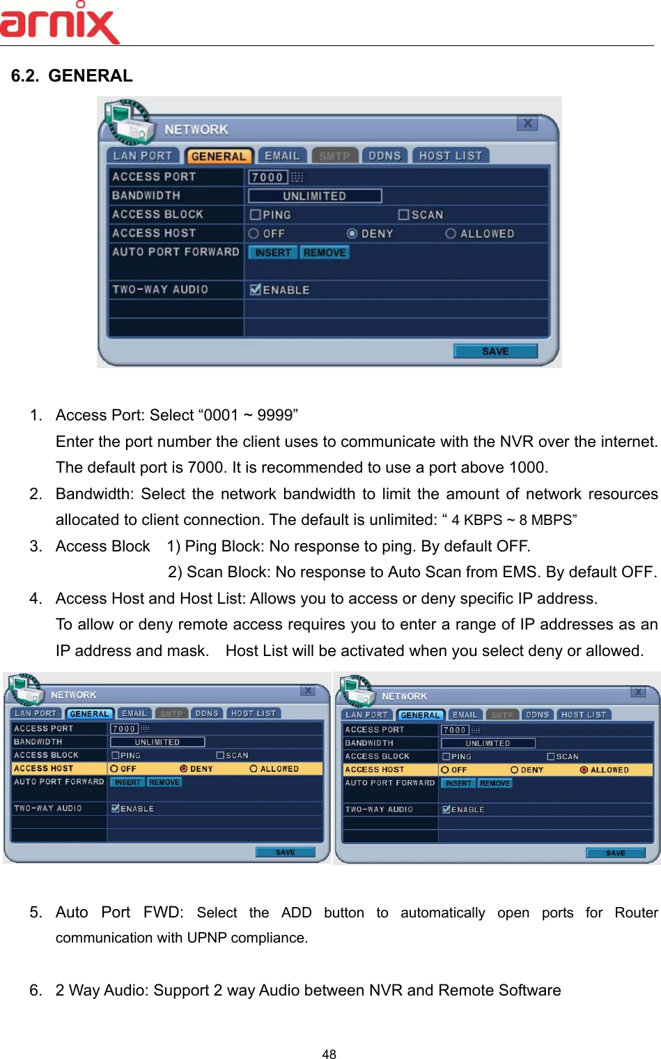
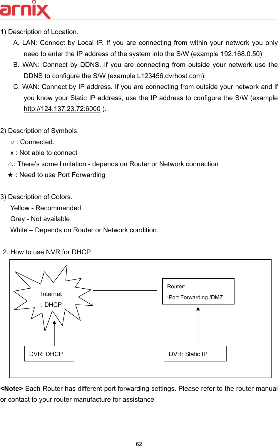
![61 6.6 Router & Port Forwarding A majority of networks will often consist of a single IP address which shares internet access through a router. This IP address may be any external (public) static IP address or any dynamic IP address issued by the Internet Service Provider. The purpose of a router is to enable multiple personal computers and any other devices that require internet connection to access the internet simultaneously. Most routers by default enable (open) commonly used ports so that mainstream applications such as Hypertext Transfer Protocol (HTTP, Port 80), File Transfer Protocol (FTP, Port 21), Telnet (Port 23) and Post Office Protocol 3 (POP3, Port 110) are used. To solve the firewall problem, and let a visitor into the network, the user instructs the router to allow traffic to pass through on a given port. This is known as Port Forwarding, as the router forwards (directs) all internet requests on a specific port to the local machine. With port forwarding, external visitors are able to connect to the NVR while other internal devices remain protected. Here is the example of NVR connection. Network Router NVR IP Setting PC Connect position PC Connect positionCF ① LAN ② WAN A B C B C Static IP use STATIC ○ △ X ★ ★ DHCP ○ ▲ X ☆ ★ Check the NVR IP of info and set into Router. x STATIC ○ ○ ○ ○ ○ DHCP N/A [Need Local DHCP Server] DHCP use STATIC ○ △ X ★ ★ DHCP ○ △ X ★ ★ Check the NVR IP of info and set into Router x STATIC N/A DHCP △ △ PPPOE is not supported](https://usermanual.wiki/EMW/BHA-WN400/User-Guide-2256800-Page-54.png)
![63 7. DEVICE 7.1. GENERAL 1) DISPLAY : Please decide output video resolution It can be set to the correct video resolution on the monitor. [1920*1080P (default) 800*600 1024*768 1280*720 1280*1024 1600*1200 1680*1050 1920*1080I] HDMI AUTO Automatically detects and sets the HDMI resolution on the monitor connected to the NVR. It might display “no video” if a VGA monitor is not able to support high resolution. <NOTE>In order to connect HDMI and VGA output to use both monitors, please set up as the lowest resolution without selecting HDMI AUTO. 2) Keypad Model: Select Joystick Controller and Baud Rate. 3) Extend Device: Select a model of POS/ATM. 4) PTZ Event: BHA-WC100 Model does not support this feature. 5) Alarm Out: DURATON [OFF,1SEC ~ 5 SEC]: Select Alarm duration. 6) IP CAM SET UP : After click in the menu, all IP cameras which are connected in LAN network will be listed in the IP CAM Discovery menu.](https://usermanual.wiki/EMW/BHA-WN400/User-Guide-2256800-Page-56.png)
![64 A. HOST ID : It shows HOST ID of IP camera. Please check IP camera which user want to see in monitor. B. IP : It shows current IP address of IP camera. C. MODEL : It shows type of IP camera. D. CHANNEL : User can assign channel and set up information about ID, PASSWORD and network setting. Note. Even though ID and PASSWORD is incorrect, it shows in live monitor. But user cannot change IP camera’s setting in camera menu. 2. Save changes and exit the menu, press the [MENU] button. Exit the menu without making change, press the [ESC] button. 7.2. I/O Terminal This NVR supports 4 Alarm Inputs and 1 x Relay Outputs.](https://usermanual.wiki/EMW/BHA-WN400/User-Guide-2256800-Page-57.png)
![65 2. Use the Left/Right buttons [ ] to select “I/O Terminal” menu tab. The menus are displayed with options in the left-hand column and settings in the right hand column. A cursor (highlighted menu) can be moved using the directional buttons [ ]. 3. SENSOR INPUT: Change the input type. Use the [-, +] buttons to change the values. Note. Alarm of IP camera can be configured in CAMERA menu (Chapter 2.2) 4. RELAY OUTPUT: you can configure how the Relay Outputs are controlled: automatic or manual. 1) Use: Change the output type. 2) Inactive: Select turn off method of Relay Out. a. Event (Automatic): Relay Out is turned OFF when the event expires. This setting is configured globally. b. Manual: Relay Out is turned OFF from this menu <Control>. 3) Event Edit - Press [OK] to edit multiple events. The menus are displayed with options in the left-hand column and settings in the right hand column. A cursor (highlighted menu) can be moved using the directional buttons [ ] on the IR remote or front panel. - Change the options below using the [DEC/INC] buttons on the IR remote, or click the mouse. - System menu contains below](https://usermanual.wiki/EMW/BHA-WN400/User-Guide-2256800-Page-58.png)
![66 1. HDD Disk Fail 2. Record System Fail 3. Temperature Warning. 4. Fan Lock Warning 5. Voltage Warning 6. Low RTC Battery Warning 7. External Device Event 8. Network Link Disconnected 9. Admin Login 10. Power Recovery 11. Disk Full 12. Invalid Password in Sequence 13. Auxiliary Event (Reserved ) 4) Control: Manual stops for relay output and buzzer. 5. Buzzer 1) USE ON: The Buzzer sounds if an alarm is triggered. The buzzer sounds for the duration of the RECORD TIME. This buzzer relates to Alarm Out. Configure Alarm Out to “ON” for Alarm Buzzer. OFF: Disables the ALARM BUZZER function. 2) Inactive: Select turn OFF Buzzer a. Event (Automatic): Buzzer is turned OFF when the event time expires. b. Manual: Buzzer is turned OFF from this menu <Control>. 5. Save changes and exit the menu, press the [MENU] button. Exit the menu without making changes, press the [ESC] button. 7.3. PTZ EVENT (BHA-WC100 Model does not support this feature) 8. SYSTEM 8.1. GENERAL](https://usermanual.wiki/EMW/BHA-WN400/User-Guide-2256800-Page-59.png)
![67 1. Control ID: Each NVR that is preconfigured with the control ID is enabled to respond to, and be operated by, the remote control. - To select the NVR to be controlled with the remote controller, press and hold the NVR ID button. While holding the NVR ID button, press the appropriate NVR ID number. For example, enter 05 for NVR ID 05, enter 43 for NVR ID 43 etc. Set the ID of IR controller on “00” to control multiple NVR’s at the same time, whatever the NVR ID is. 2. Device Name: Type a NVR name to distinguish its location when you have several NVR’s on a Network. 3. KEY TONE: By default, the NVR emits a beep every time a button is pressed. Set the key tone to OFF to turn the button beep off. By default it’s “ON” 4. AUTO LOGOUT: You can configure the NVR to automatically log users out. By default it’s “OFF”. [OFF 1 Minute 3 Minute 5 Minute 10 Minute] 5. S.M.A.R.T. CHECK: Turn ON or OFF to display HDD information in the SMART STATUS tab of the DISK menu. 8.2. TIME Make sure to set up your Date and Time before starting to Record.](https://usermanual.wiki/EMW/BHA-WN400/User-Guide-2256800-Page-60.png)
![68 1. Use Left/Right buttons [ ] to select on “Time” menu tab. The menus are displayed with options in the left-hand column and settings in the right hand column. A cursor (highlighted menu) can be moved using the directional buttons [ ]. Press the [-, +] buttons to change the values. 1) Time Zone: Refer to <Appendix 1: Time Zone Chart> Selects the time zone where the NVR is located. Time Zone contains DST (Daylight Saving Time) ON. If you choose Time Zone with DST, there is no change in the system time stamp for recorded data. When the Daylight Saving End date and time occurs the NVR’s time goes back one hour. 2) Date Format: Select Date display format. [ MM/DD/YYYY DD/MM/YYYY YYYY/MM/DD ] 3) NTP SYNC: The internal time of NVR can be synchronized with an external time source using NTP (Network Time Server) Configuration. If the NTP option is ON, the DATE and Time option is inactivate. 4) NTP Server: Allows you to use a public or private NTP server. Enter the IP address of the server or domain. The default setting is public “pool.ntp.org”. <Note> Time Sync. Interval: Min 64 sec. Max 1024 sec. 5) NTP TEST: Test whether NTP Server works or fails. 6) Date & Time: Set current time and date. 2. Save changes and exit the menu, press the [MENU] button. Exit the menu without making changes, press the [ESC] button.](https://usermanual.wiki/EMW/BHA-WN400/User-Guide-2256800-Page-61.png)
![69 8.3. ACCOUNT . 1. Use the Left/Right buttons [ ] to select “Account” menu tab. The menus are displayed with options in the left-hand column and settings in the right hand column. A cursor (highlighted menu) can be moved using the directional buttons [ ]. Press [-, +] buttons to change the values. 1) User/Name: The NVR comes preconfigured with ADMIN. Select a User 1~10, and then activate it by setting to ON. a. Name Length: up to 10 characters. b. Characters: A to Z, numerals 0 to 9. 2) Privilege: Admin can define each user’s Privilege, such as PLAYBACK, PTZ CONTROL, BACKUP, CONFIGURATION (except for Disk and System), RECORD STOP, and SYSTEM SHUTDOWN. 3) Network PASSWORD: The NVR comes preconfigured with a System Password for Network access for Admin and/or Deny for User. It is possible to create different passwords for Network access; choose using [Custom P/W]. a. Password Length: up to 14characters. b. Characters: A to Z, numerals 0 to 9.](https://usermanual.wiki/EMW/BHA-WN400/User-Guide-2256800-Page-62.png)
![70 4) Usable Channel Allow each user different live channels for monitoring. 5) Password Enter the 6 characters for the new password, and then re-enter the same password under the COMFIRM section. An asterisk is displayed for each character entered. 2. Save changes and exit the menu, press the [MENU] button. Exit the menu without making changes, press the [ESC] button. 8.4. UPDATE 1. Download the latest firmware file and copy to USB Flash memory stick in the Root directory. 2. Connect or insert into Front USB (please stop recording first). 3. Use directional buttons to move to the [Start] button. Press the [+] button to find upgrade files. If the NVR finds a valid upgrade file, the update menu is activated. 4. Press the [-, +] buttons to find correct upgrade file. Version information is displayed. If there are several valid update files, please check the display for the correct one. <NOTE > Please make sure you download all of files below (20M). hd4k_all.00.00.00.img](https://usermanual.wiki/EMW/BHA-WN400/User-Guide-2256800-Page-63.png)
![71 5. Use the directional buttons to move to the [Start] button, then press [OK] button to start updating. While updating, ”in progress” message is displayed. 6. After the update process is complete, a “Success” message is displayed. Press the [OK] button to restart. 8.5. INFO Press [info] button on IR remote or select icon on the menu. The system information is displayed. SUMMARY : It contains brief model information, Mac Address and installed HDD status NOTE 1 Do not switch OFF or PRESS any key during the update process. NOTE 2 Please consult your distributor or installerbefore update this.](https://usermanual.wiki/EMW/BHA-WN400/User-Guide-2256800-Page-64.png)
![72 DISK : It contains all DISK information including internal & external HDDs and USB memory. NETWORK : It shows IP address, USER and service of NET user. VI. PLAYBACK /SEARCH The NVR supports 2 playback modes; Playback and Search. The NVR offers a variety of search functions that enable you to quickly and efficiently locate and review a specific period from the database. It supports three different search modes: Date/Time, Event, Event Area and Log Search. 1. Playback When the [PLAY] button is pressed, the NVR starts to play back any recorded data from the latest data, whether in live or recording mode. When the NVR reaches the end of the recorded data, it stops the playback. During the playback, the NVR may be played back in reverse, paused, speed search up](https://usermanual.wiki/EMW/BHA-WN400/User-Guide-2256800-Page-65.png)
![73 to 16 times the normal speed, or move through picture by picture. 2. Time Search 2.1 Multi Channel Playback 1. Press the [Time Search] button to access the time search table. Day will be displayed. The data is color-coded by category: EVENT (Red) > Normal (Yellow) 2. Use the [+] button to navigate to the desired DayHourMinute (5min) Minute (30 sec). Use the [-] button to go back minute (30sec) Minute (5min) HourDay. When using the mouse, the wheel is used for the [+/-] button. <Note> Use the [Play] button to move to the end of data Use the [Rewind] or [Fast-forward] buttons to move to the next page. 3. To review all channels, press the [OK] button on the slot on the bar. When using the mouse, double click. 4. The NVR starts the playback mode, displaying all channels. Any channel number or the DISPLAY button may be pressed to change the display mode. 2.2 Preview Search (Single Channel Playback) The NVR allows you to quickly review a single channel of playback over a period of Day, Hour, and Minute. 1. Press the [Time Search] button to access the time search table. Day will be displayed. Day, Hour, Minute Channel](https://usermanual.wiki/EMW/BHA-WN400/User-Guide-2256800-Page-66.png)
![74 2. Choose the desired channel to review by pressing a numeric button or Click Channel number on the left. Click to return (to chart) 3. Use the [+] button to navigate to the desired DayHourMinute (5min) Minute (30sec). Use the [-] button to go back minute (30sec) Minute (5min) HourDay. When using the mouse, the wheel is used for [+/-] button. 4. While reviewing snapshot, use numeric buttons to review other channel. 5. Use the directional button to select snapshot and, press the [OK] button. Using mouse, double click. 6. The NVR starts the playback mode, displaying the selected channel. Any channel number, or the DISPLAY button, can be pressed to change the display mode. 2.3 Event Record Search Event Record search feature allows you to search for recorded video by event. The time search table displays time events. As a default, the TIME SEARCH CHART displays CONTINUOUS recording (Yellow) and EVENT recording (Red). Channel Day, Hour, Minute](https://usermanual.wiki/EMW/BHA-WN400/User-Guide-2256800-Page-67.png)
![75 TIME SEARCH CHART displays different outcomes according to the SEARCH MODE below. [FIGURE 1] 1. Press the “Event Select “button to change search mode. 2. Press [OK] to set up. Press [+/-] button to select “event record”. 3. Press [+/-] button to select “SEARCH MODE “(Event Source /Motion Area). By selecting Search Mode, TIME SEARCH CHART displays different outcomes. <Note> EVENT RECORD is set by default and makes the TIME SEARCH CHART display EVENT recording in Red as above FIGURE 1. 2.4 Event Source Search Event source search feature allows you to search the recording data for ALARM, MOTION and VLOSS events previously triggered on the NVR.](https://usermanual.wiki/EMW/BHA-WN400/User-Guide-2256800-Page-68.png)
![76 1. Press [+/-] button to select “Event Source” in search mode. And select the event source (Alarm, Motion, Vloss) which you want to search. 1) ALARM: Select Alarm Input 1~4. 2) MOTION: Select the channel 1~16. 3) VLOSS (Video Loss): Select the channel 1~16. 4) SYSTEM: Inactivated 2. Users can have multiple selections by pressing icon, as shown below. 2.5 Motion Area Search (Single Channel Playback) The NVR searches for recorded video that matches the search area defined by selected cells. 1. Select “MOTION AREA” (single channel playback) to search the recording data that has motion in a specific area on a certain channel.](https://usermanual.wiki/EMW/BHA-WN400/User-Guide-2256800-Page-69.png)
![77 2. Press the [+/-] button to select the channel you want to search. 3. Select the motion area you want to search. : Select all grids : Deselect all grids : Select grids, one by one, by pressing the [+/-] button 4. Press the MENU button and the TIME SEARCH CHART displays recording data, in red, to show what’s happened on that channel. 3. Go to Search](https://usermanual.wiki/EMW/BHA-WN400/User-Guide-2256800-Page-70.png)
![78 1. Press the [Time Search] button for 2 second and the [Time Input] menu pops up. 2. Set the date and time you wish to search. 3. Press [OK] or [Menu] to start searching. 4. Log List Search](https://usermanual.wiki/EMW/BHA-WN400/User-Guide-2256800-Page-71.png)
![79 The logs can be used to search, and to review, any point in time of the recorded data. Alarm, Motion, Video Loss and system related logs can be searched and played back directly from the time of the incident. 1. To start an Event Search, press the [Log] button on the IR Remote and the Log List Menu pops up, as shown below. 2. Use the Up/Down buttons [] to the desired “Time” to playback. Use the Left/Right buttons [] to move to the NEXT page. 3. Press the [OK] button to start playback. MENU TAB CONDITION ALL A list of all events since the initial NVR power on procedure. SYSTEM Shows the System List. NETWORK Shows the NETWORK List. EVENT Shows the Events List. VIDEO LOSS Shows Video Loss List. <Note> 1) Log list is saved on HDD. 2) For more detailed information press](https://usermanual.wiki/EMW/BHA-WN400/User-Guide-2256800-Page-72.png)
![80 VII. BACKUP 1. Manual Back Up 1.1 External DVD- R/W 14. External USB-HDD, CD/DVD-RW is recognized within 10 seconds after plug in UBS connection cable to UBS port in DVR. 1. Plug in USB connector into the USB connection port on the front panel. 2. Press [BACKUP] button to display the backup menu. 1. Use the [-, +] buttons to change device selection: USB CD/DVD RW 2. Use the [-, +] button to select a channel. All channels are set by default. 3. Select the data for BACKUP. (1) ALL Data: Normal Recording Data (2) Event Only: Event Recording Data. 4. File format when saving is “.s” AVI is not supported for CD/DVD 5. Select the time range starting time and ending time. 6. Enter the numbers as required in 24-hour format, then move to . 7. Press the [+] button to start BACKUP.. 15. The progress of the backup is displayed at the bottom of the window as a percentage of the entire backup process. The OSD disappears by pressing cancel button. However, pressing the Backup button again will show the Backup status. It is recommended that playback is not performed while the NVR is in a backup session..](https://usermanual.wiki/EMW/BHA-WN400/User-Guide-2256800-Page-73.png)
![81 8. When finished, the media is ejected. 16. If there is not enough space on the media the NVR automatically ejects the disk when it’s full and resume the process once new media is inserted into the drive. * The CD Playback software will simply “auto-run” and does not require any software installation on your PC. <Note> Please Refer to [LOCAL PLAYER] section to read about back-up devices. <Note 2> When you back up as Multi-Section the Play List pops up instead of Auto Run. Channel Select FF/FR Watermark Play Stop](https://usermanual.wiki/EMW/BHA-WN400/User-Guide-2256800-Page-74.png)
![82 1.2 External USB HDD/ Memory Stick The external drive procedure is the same as using the internal CD/DVD-RW for backup. To read USB backup HDD in Window, format to FAT32 or NTFS. To backup as an AVI File, set the file format to AVI using the [+] button. 1.3 Back up Range Setup Press the [◄▌] button to set backup start time and press the [▐►] button to set the end. Selected time changes to a Violet color. Selected backup time is displayed on the backup range. [LOG IN/OUT] button is toggled for the range.](https://usermanual.wiki/EMW/BHA-WN400/User-Guide-2256800-Page-75.png)
![83 2. Auto Back Up (FTP) 1. Use the [-, +] button to change the selected device to FTP 2. Use the directional buttons to move to FTP Setup. The menus are displayed with options in the left-hand column and settings in the right hand column. <Note> Please Refer to [LOCAL PLAYER]/ [Mini-Player] section to read about back-up file ITEM ADJUSTMENT Server Select Highlight FTP Server and then press numeric buttons to define an FTP server. Port Define the port that the FTP server will communicate through. User ID Enter the user ID of FTP Server. Password Enter the password. Connection Select PASSIVE mode or REGULAR Mode. BACKUP PATH The path should be made in the FTP server in advance. Mac address is set with the default in consideration of the scenario where lots of NVR’s backup files to the same FTP server.](https://usermanual.wiki/EMW/BHA-WN400/User-Guide-2256800-Page-76.png)
![84 3. Log List Back Up 1. Plug the USB memory stick into the USB port. 2. Press the “Log” button to see the NVR Log List. ( Click Log icon on the upper left by mouse) 3. Press the “back up” button to save the log list to USB memory stick. 1) Use the [-, +] buttons to select a device. 2) Select type of Log List from ALL, SYSTEM, NETWORK, EVENT and VLOSS. 3) Select the time range - start and end time. 4) Press the [+] button to start the BACKUP.](https://usermanual.wiki/EMW/BHA-WN400/User-Guide-2256800-Page-77.png)
![85 VIII. WIRELESS 1. CAMERA 1.1 List - The list shows the IP Cameras that are currently connected to NVR wireless module. 1) Channel : User can change the channels by using [-, +] button. 2) HOST ID: Shows IP Camera’s name. 3) IP Address: Shows IP Camera’s IP address](https://usermanual.wiki/EMW/BHA-WN400/User-Guide-2256800-Page-78.png)
![86 4) Model Description: Shows the description on the IP Camera. 5) ※ : Shows the wireless module number of the NVR 1.2 Auto Link 1) Use Up/Down [] buttons and Left/Right [] buttons to select Auto Link 2) Automatically connects the IP Cameras to unoccupied channels. 1.3 Refresh 1) Use Up/Down [] buttons and Left/Right [] buttons to select refresh 2) Automatically refreshes to scan for IP Cameras that are connected to the wireless network. 2. STATUS 2.1 List - Shows the current status of the wireless module on the NVR. 1) B-CDMA ID : Shows ID of the wireless module on NVR. 2) F/W VERSION : Shows the firmware’s version of the wireless module on NVR. 3) PID : Shows ID used to wirelessly communicate on the PICONET. - PICONET ID must be matched between IP Cameras and NVR in order to establish wireless connection. 4) CID : Shows the connected frequency channel. - 2.4GH : Channel 0~4 - 5.8GH : Channel 12~19 5) STN : Shows the connected numbers of NVRs and IP Cameras. - STN = NVR(1ea) + IP Cameras 6) Status: Shows the current status of the wireless module on the NVR.](https://usermanual.wiki/EMW/BHA-WN400/User-Guide-2256800-Page-79.png)
![87 3. SETUP 1) MODULE NO : User can change the module by using [-, +] button. 2) PICONET ID : User can change the ID by using [-, +] button. - This ID is used for establishing wireless connection and it is chageable. But the ID must match IP Camera’s ID in order to establishing the succesful wireless connection. 3) FREQUENCY : Selectable from 2.4GHz, 5.8GHz, and 2.4/5.8GHz. 4) Channel : Selectable from AUTO, MANUAL - AUTO : Automatically allocated to the channels. - MANUAL : Manually allocated to the channels. 5) RF POWER : User can set the RF power of the module. - Low power settings are suggested when the distance from IP Camera to NVR is close and High power settings are suggested when the distance from IP Camera to NVR is far. 6) ENCRYPTION : User can choose whether the wireless signal transmission will use encryption feature or not. Enabling this feature may decrease the wireless transmission rate by a little. 7) CHANNEL AVOIDANCE : User can choose whether the wireless signal transmission will use channel avoidance feature or not. - If the channel setting is on “Manual”, this feature will not be enabled. 8) MODULE REBOOT : NVR forces the wireless module to reboot by clicking this button.](https://usermanual.wiki/EMW/BHA-WN400/User-Guide-2256800-Page-80.png)