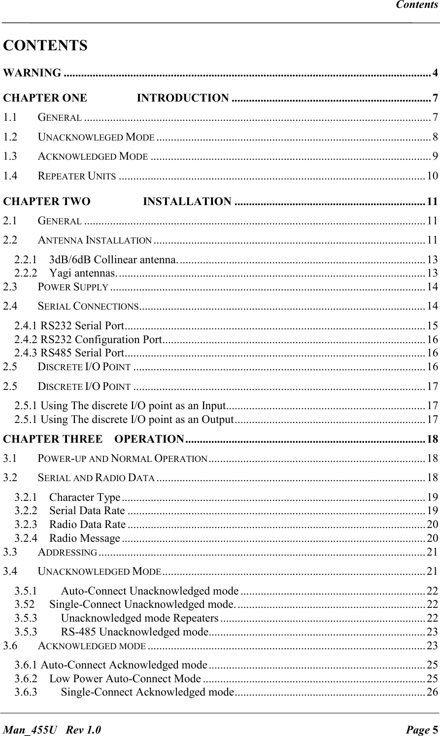
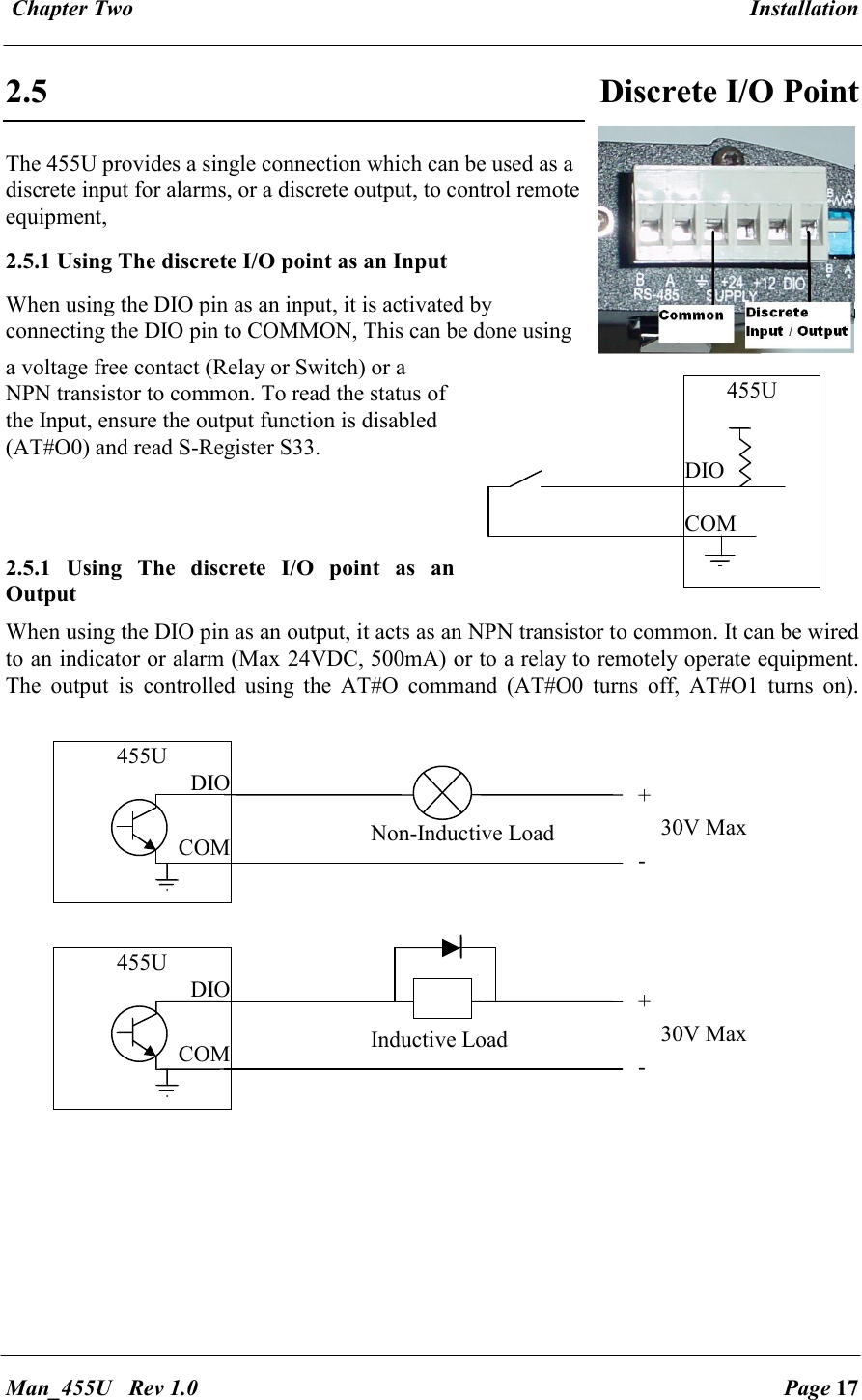
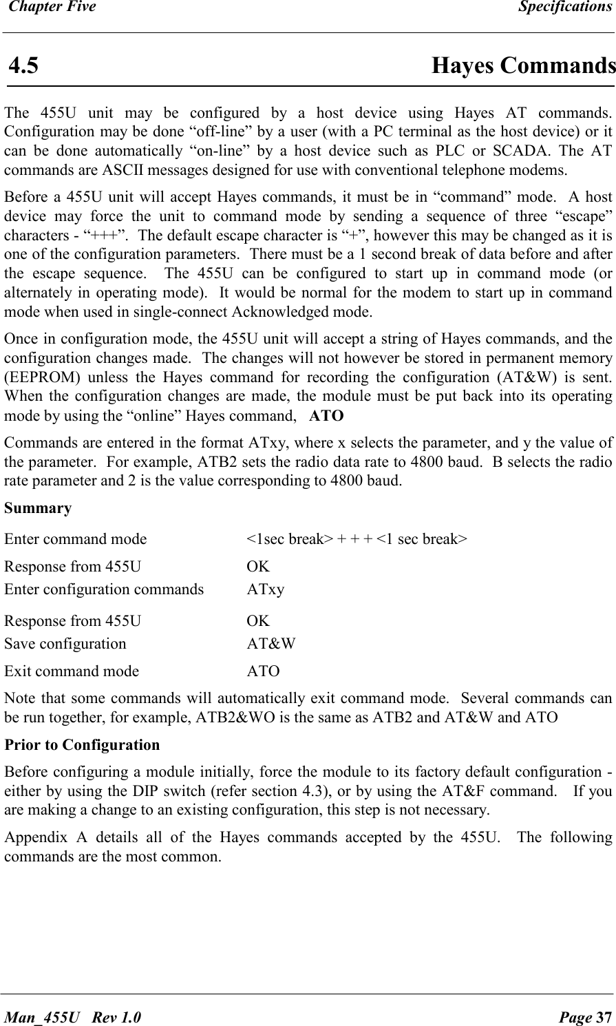
ELPRO Technologies P450H FIXED / BASE UHF TRANSCEIVER User Manual Man 455U 1 4
ELPRO Technologies Pty Ltd FIXED / BASE UHF TRANSCEIVER Man 455U 1 4
UserManual.wiki
>
ELPRO Technologies
>
P450H User Manual
USERS MANUAL
Navigation menu
Upload a User Manual
Namespaces
Wiki Guide
HTML
PDF
Info
Views
User Manual
Discussion / Help
Navigation

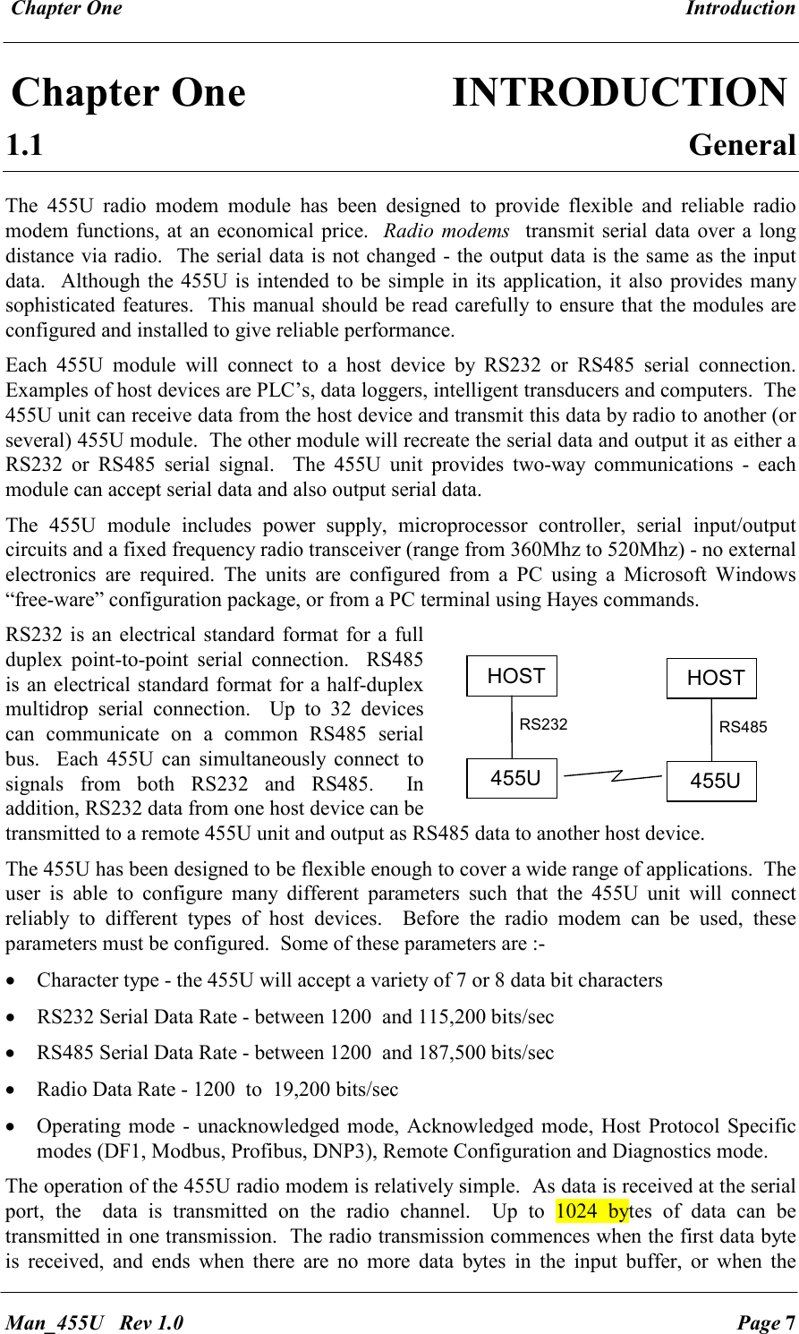
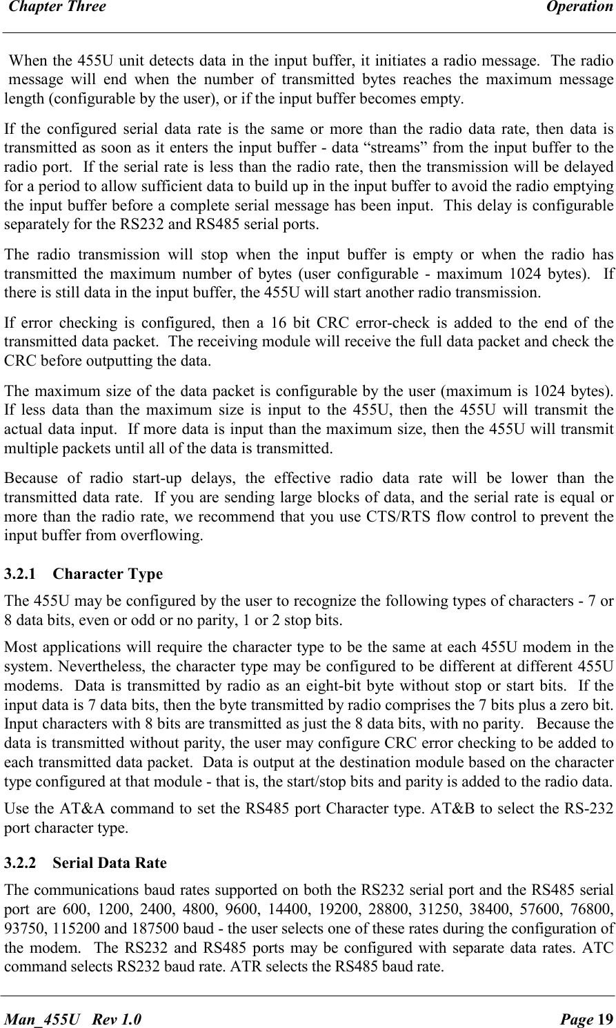
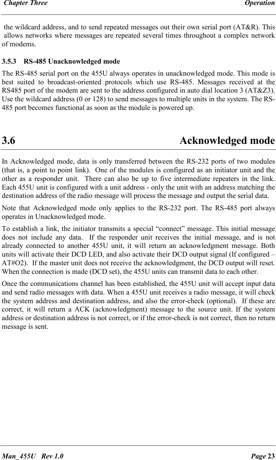
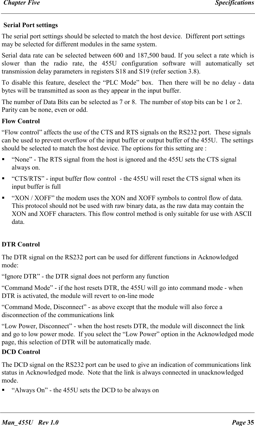
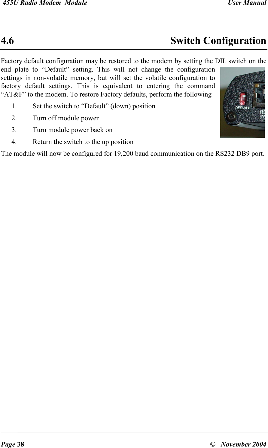
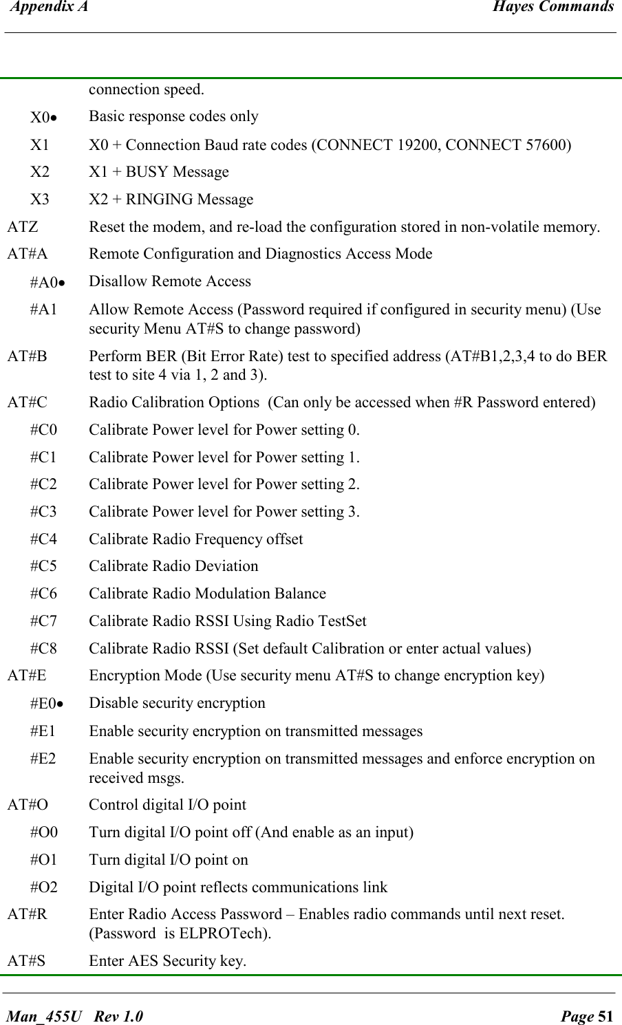
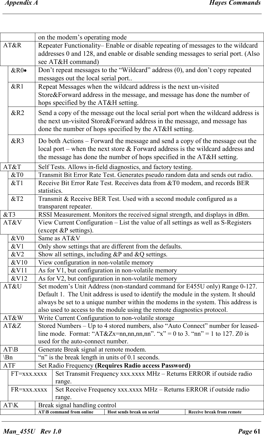
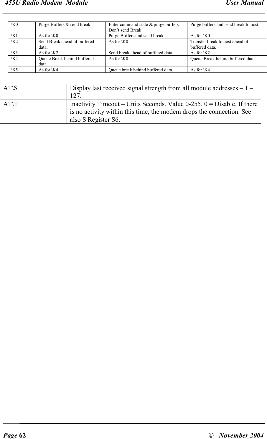
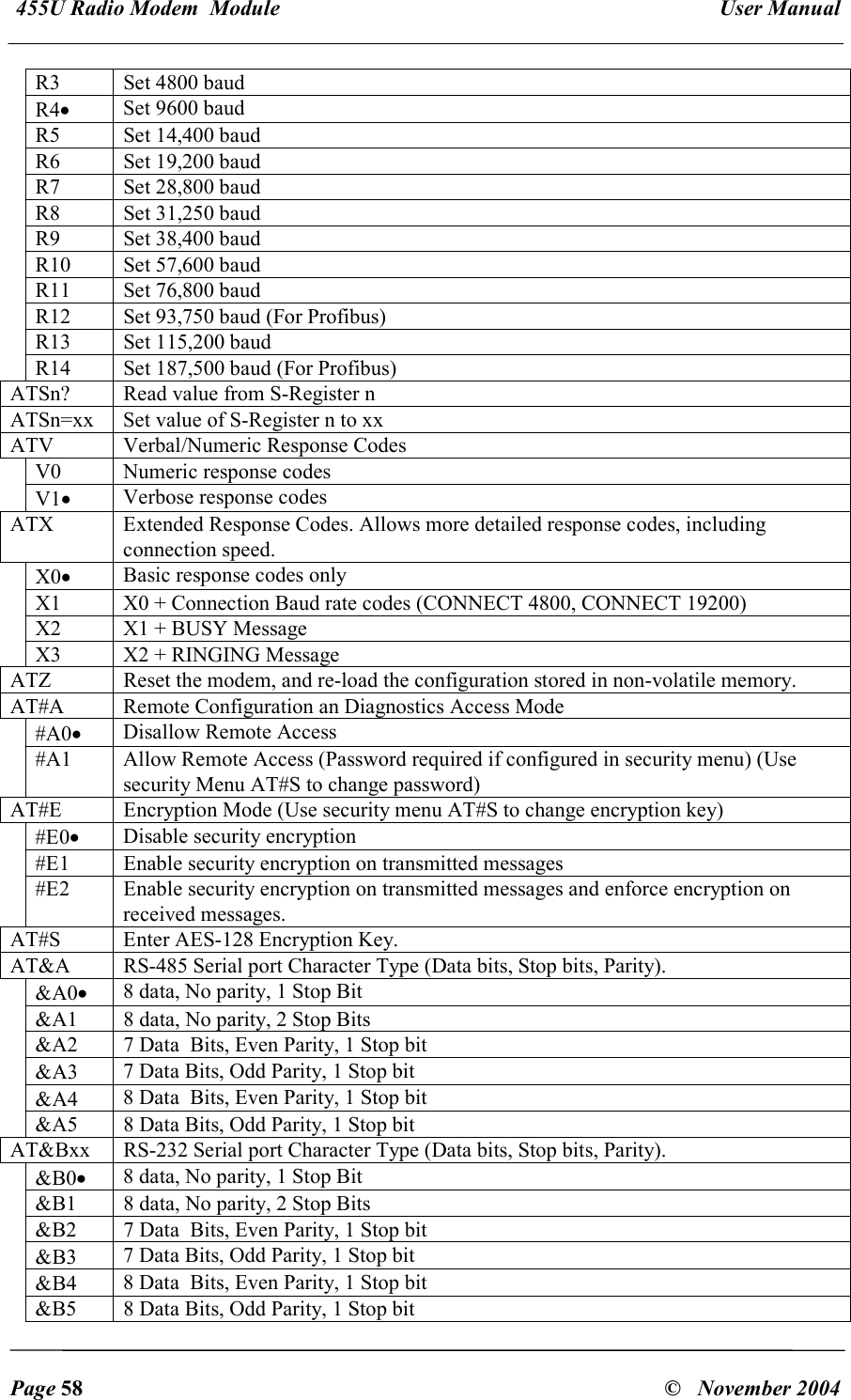
![455U Radio Modem Module User Manual Page 54 © November 2004 In this mode, Messages on the RS-485 port are sent the the address configured in register &Z1. Messages on the RS-232 port are sent to the address dialled from the command line, or configured in the auto-dial register &Z0. &M1 Acknowledged mode. This mode simulates telephone modems, with a single connection being made to a remote modem in the system, and each message is acknowledged before more data is sent. If no Acknowledgement is received, the message is re-transmitted. &M3 &M4 etc Host protocol specific modes. AT&N Abort Connection Control. Controls whether the modem will abort a connection attempt if a character is entered. This item is only meaningful with the acknowledged mode of operation. &N0 Ignore characters entered while attempting to make a connection. &N1• If a key is hit while attempting to connect, abort the connection attempt and return to command mode. AT&P Protocol Routing Paths – Up to 100 paths can be stored. Routing paths are used in conjunction with host protocol specific routing, so that device addresses may be extracted from the data frame and used to direct the message. Each path consists of a destination address extracted from the protocol frame, a radio destination address and up to 6 store and forward addresses. Format: 1. “AT&Pxx= a[-a]:{n,}f”. “xx” = 0 to 99. “a” = 0 to 65535 (depending on protocol). “n” = 0 to 127, “f” = 0 to 255. This indicates the path to send the message. “a” is the protocol address to match. (“a-a” indicates a range of addresses) “n” indicates a repeater address in the radio network, and “f” indicates the final address (0-127 indicates RS232 port, 128-255 indicates RS485 port) 2. “AT&Px=” “x” = 0 to 99. Clear path number “x” 3. “AT&Px?”. “x” = 0 to 99. Display setting for Path “x” 4. “AT&P?” or “AT&P” – Display all configured paths 5. “AT&P=” Clear all paths These paths may apply to either the RS-232 port or the RS-485 port depending on the modem’s operating mode AT&R Repeater Functionality– Enable or disable repeating of messages to the wildcard addresses 0 and 128, and enable or disable sending messages to serial port. &R0• Don’t repeat messages to the “Wildcard” address, and don’t copy repeated messages out the local serial port.. &R1 Repeat Messages sent to the wildcard address. &R2 Send A copy of repeated messages out the serial port (RS-232 or RS-485 port](https://usermanual.wiki/ELPRO-Technologies/P450H/User-Guide-626316-Page-53.png)
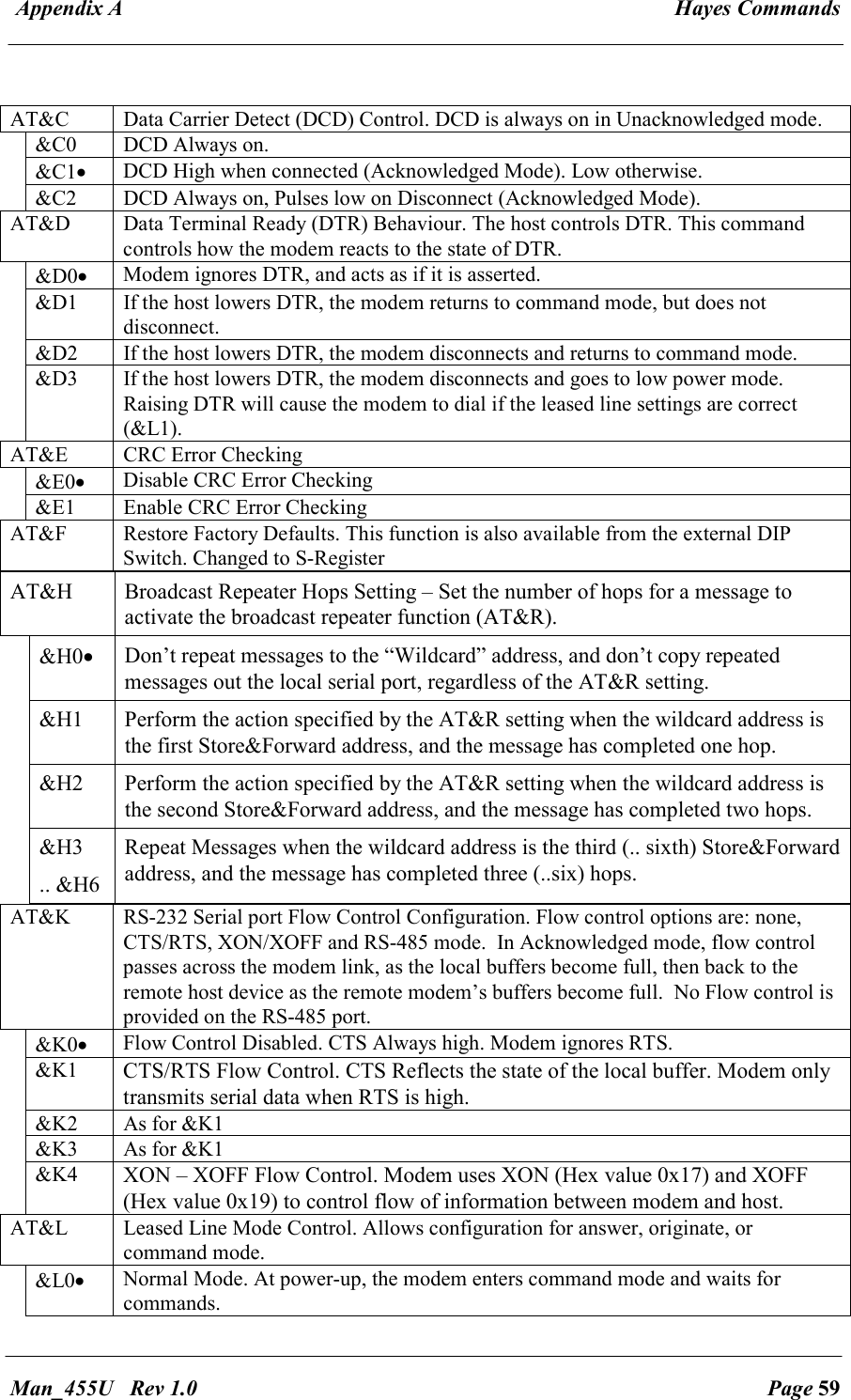
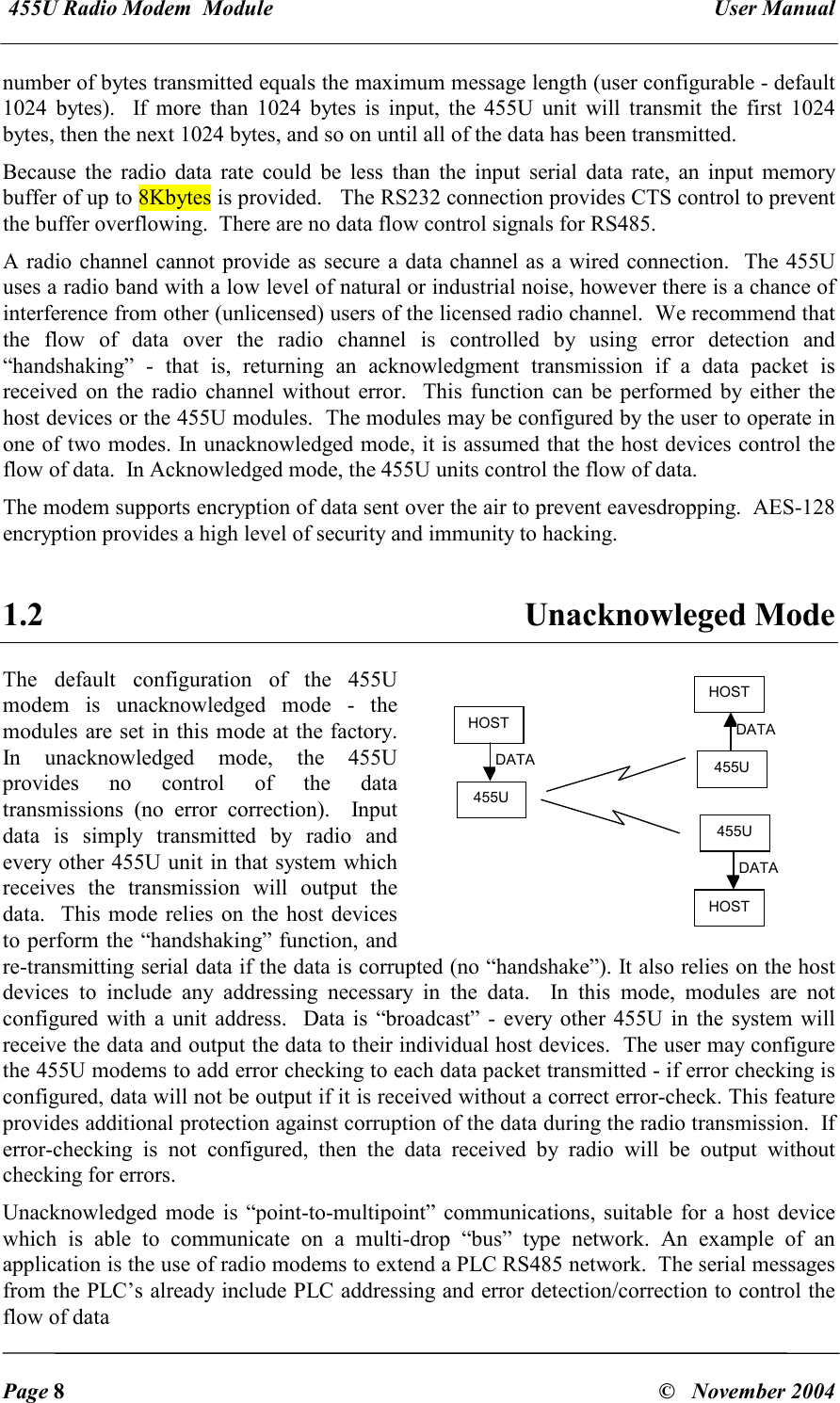
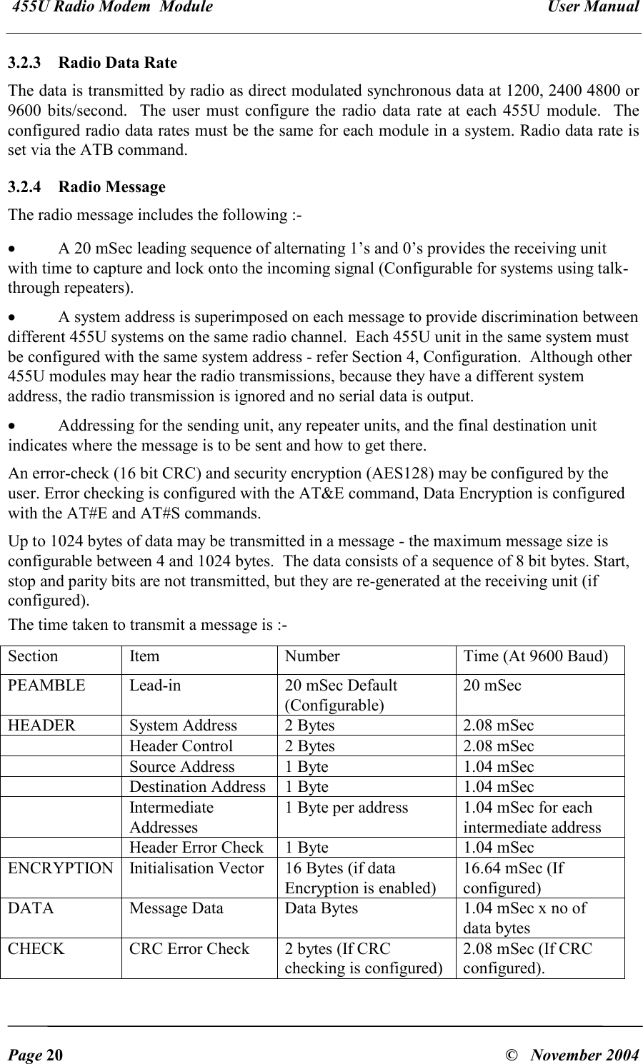
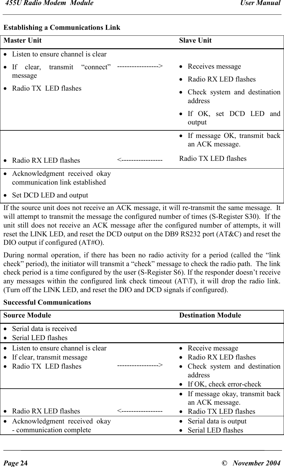
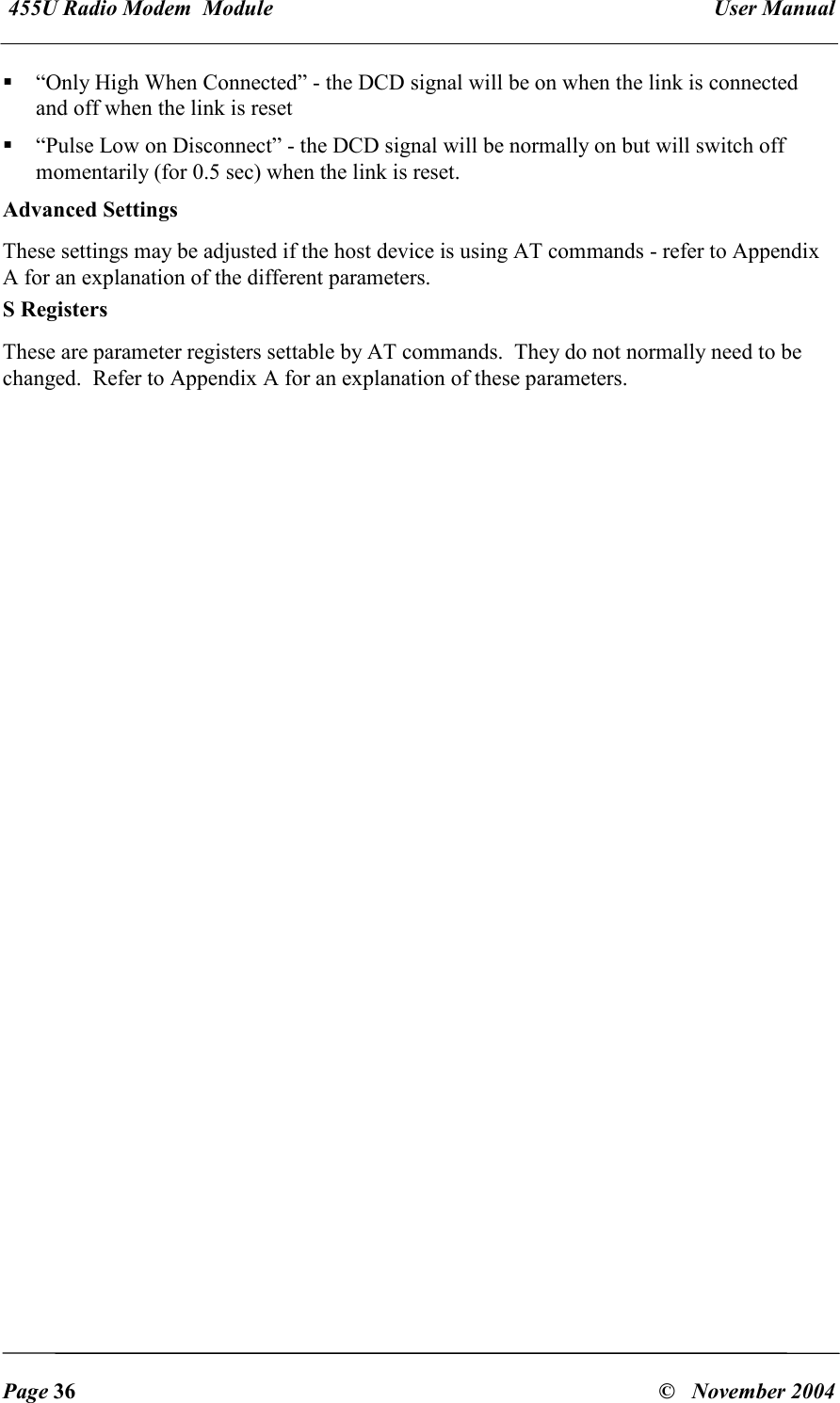
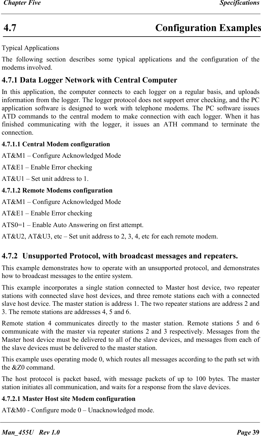
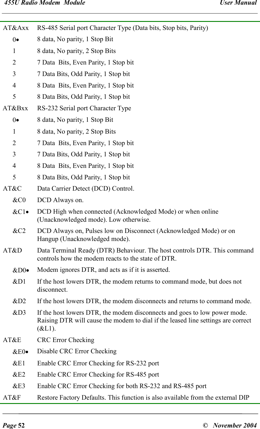
![455U Radio Modem Module User Manual Page 60 © November 2004 &L1 Leased Line mode. For Acknowledged mode, The modem automatically dials the number stored in Z0, ATA answers an incoming call. For Unacknowledged modes, the modem automatically goes online, and sends messages to the modem configured in Z0. &L2 Leased Line Answer mode. The modem continuously attempts to answer any incoming call. Use DTR with the AT&D command to control the connection. This mode is only allowed when operating in Acknowledged mode. AT&M Operating Mode. This allows selection between unacknowledged mode, acknowledged mode and the different protocol specific modes. &M0• Unacknowledged Mode. All serial data is sent to the configured destination address (In Z0 or specified in a dial command). No Acknowledgement is required, and broadcast messages are allowed by using the wildcard address “0”. In this mode, Messages on the RS-485 port are sent the the address configured in register &Z1. Messages on the RS-232 port are sent to the address dialled from the command line, or configured in the auto-dial register &Z0. &M1 Acknowledged mode. This mode simulates telephone modems, with a single connection being made to a remote modem in the system, and each message is acknowledged before more data is sent. If no Acknowledgement is received, the message is re-transmitted. &M2 Host protocol specific modes. &M3 etc AT&N “Abort Connection” Control. Controls whether the modem will abort a connection attempt if a character is entered. This item is only meaningful with the acknowledged mode of operation. &N0 Ignore characters entered while attempting to make a connection. &N1• If a key is hit while attempting to connect, abort the connection attempt and return to command mode. AT&P Protocol Routing Paths – Up to 100 paths can be stored. Routing paths are used in conjunction with host protocol specific routing, so that device addresses may be extracted from the data frame and used to direct the message. Each path consists of a destination address extracted from the protocol frame, a radio destination address and up to 6 store and forward addresses. Format: 1 “AT&Pxx= a[-a]:{n,}f”. “xx” = 0 to 99. “a” = 0 to 65535 (depending on protocol). “n” = 0 to 127, “f” = 0 to 255. This indicates the path to send the message. “a” is the protocol address to match. (“a-a” indicates a range of addresses) “n” indicates a repeater address in the radio network, and “f” indicates the final address (0-127 indicates RS232 port, 128-255 indicates RS485 port) 2 “AT&Px=” “x” = 0 to 99. Clear path number “x” 3 “AT&Px?”. “x” = 0 to 99. Display setting for Path “x” 4 “AT&P?” or “AT&P” – Display all configured paths 5 “AT&P=” Clear all paths These paths may apply to either the RS-232 port or the RS-485 port depending](https://usermanual.wiki/ELPRO-Technologies/P450H/User-Guide-626316-Page-59.png)