EDMO Distributors FL760A VHF AM TRANSCEIVER User Manual Instructions manual 080207

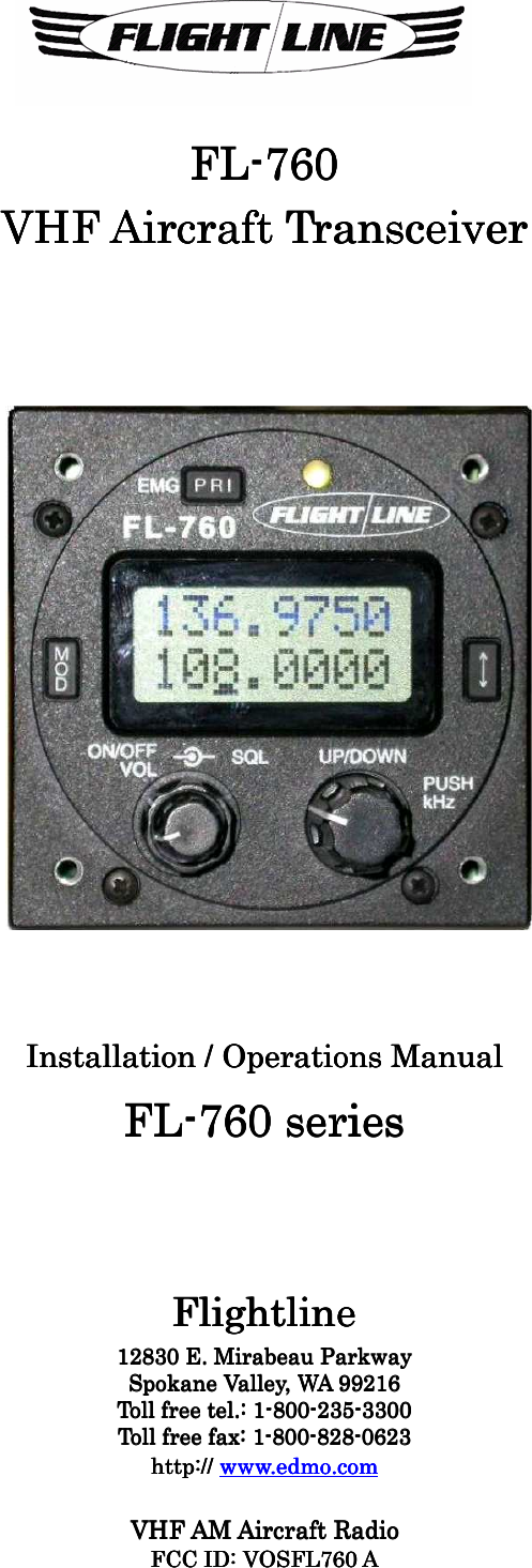
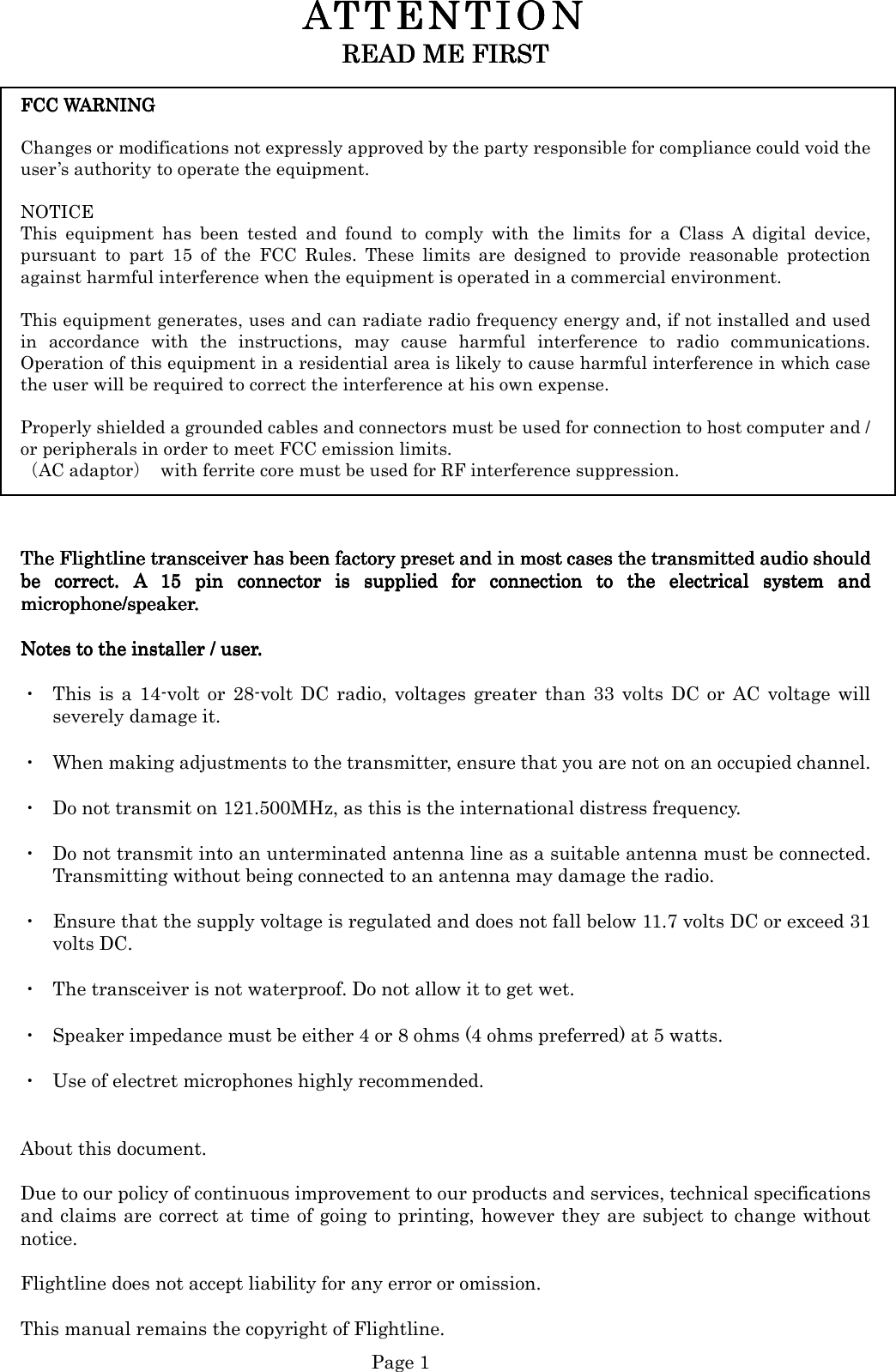
EDMO Distributors, Inc VHF AM TRANSCEIVER Instructions manual 080207

Manual

  Page 0      FLFLFLFL----760760760760    VHFVHFVHFVHF    AircraftAircraftAircraftAircraft    TransceiverTransceiverTransceiverTransceiver                                                    Installation / OperationInstallation / OperationInstallation / OperationInstallation / Operations Manuals Manuals Manuals Manual    FLFLFLFL----760 series760 series760 series760 series            FlightlineFlightlineFlightlineFlightline    12830 E. Mirabeau Parkway 12830 E. Mirabeau Parkway 12830 E. Mirabeau Parkway 12830 E. Mirabeau Parkway      Spokane Valley, WA 99216Spokane Valley, WA 99216Spokane Valley, WA 99216Spokane Valley, WA 99216    Toll freeToll freeToll freeToll free tel. tel. tel. tel.: 1: 1: 1: 1----800800800800----235235235235----3300330033003300    Toll free faxToll free faxToll free faxToll free fax: 1: 1: 1: 1----800800800800----828828828828----0623062306230623    http:// http:// http:// http:// www.edmo.comwww.edmo.comwww.edmo.comwww.edmo.com        VHF AM Aircraft RVHF AM Aircraft RVHF AM Aircraft RVHF AM Aircraft Raaaadiodiodiodio    FCC ID: FCC ID: FCC ID: FCC ID: VOSFL760 AVOSFL760 AVOSFL760 AVOSFL760 A
  Page 1 ATTENTION ATTENTION ATTENTION ATTENTION      READ ME FIRSTREAD ME FIRSTREAD ME FIRSTREAD ME FIRST        FCC WARNING FCC WARNING FCC WARNING FCC WARNING       Changes or modifications not expressly approved by the party responsible for compliance could void the user’s authority to operate the equipment.  NOTICE   This  equipment  has  been  tested  and  found  to  comply  with  the  limits  for  a  Class  A  digital  device, pursuant  to  part  15  of  the  FCC  Rules.  These  limits  are  designed  to  provide  reasonable  protection against harmful interference when the equipment is operated in a commercial environment.    This equipment generates, uses and can radiate radio frequency energy and, if not installed and used in  accordance  with  the  instructions,  may  cause  harmful  interference  to  radio  communications. Operation of this equipment in a residential area is likely to cause harmful interference in which case the user will be required to correct the interference at his own expense.  Properly shielded a grounded cables and connectors must be used for connection to host computer and / or peripherals in order to meet FCC emission limits.   (AC adaptor)  with ferrite core must be used for RF interference suppression.         The FlightThe FlightThe FlightThe Flightline transceiver has been factory preset and in most cases the transmitted audio shouldline transceiver has been factory preset and in most cases the transmitted audio shouldline transceiver has been factory preset and in most cases the transmitted audio shouldline transceiver has been factory preset and in most cases the transmitted audio should         be  correct.  A  15  pin  connector  is  supplied  for  connection  to  the  electrical  sybe  correct.  A  15  pin  connector  is  supplied  for  connection  to  the  electrical  sybe  correct.  A  15  pin  connector  is  supplied  for  connection  to  the  electrical  sybe  correct.  A  15  pin  connector  is  supplied  for  connection  to  the  electrical  system  andstem  andstem  andstem  and    microphone/speaker.microphone/speaker.microphone/speaker.microphone/speaker.     NotesNotesNotesNotes to the installer / user. to the installer / user. to the installer / user. to the installer / user.     ・  This  is  a  14-volt or  28-volt  DC  radio,  voltages  greater  than  33  volts  DC  or  AC  voltage  will severely damage it.  ・  When making adjustments to the transmitter, ensure that you are not on an occupied channel.  ・  Do not transmit on 121.500MHz, as this is the international distress frequency.  ・  Do not transmit into an unterminated antenna line as a suitable antenna must be connected. Transmitting without being connected to an antenna may damage the radio.  ・  Ensure that the supply voltage is regulated and does not fall below 11.7 volts DC or exceed 31 volts DC.  ・  The transceiver is not waterproof. Do not allow it to get wet.  ・  Speaker impedance must be either 4 or 8 ohms (4 ohms preferred) at 5 watts.  ・  Use of electret microphones highly recommended.   About this document.  Due to our policy of continuous improvement to our products and services, technical specifications and claims are correct at time of going to printing, however they are subject to change without notice.  Flightline does not accept liability for any error or omission.  This manual remains the copyright of Flightline.
  Page 2 TABLE OF CONTENTSTABLE OF CONTENTSTABLE OF CONTENTSTABLE OF CONTENTS    SECTION                                                                 Page ATTENTIONATTENTIONATTENTIONATTENTION----     READ  ME  FIRST READ  ME  FIRST READ  ME  FIRST READ  ME  FIRST  …………………………………………………………………………………………………………………………………………………………………………………………………………....1111    TABLE  OF  CONTEN TSTABLE  OF  CONTEN TSTABLE  OF  CONTEN TSTABLE  OF  CONTEN TS ………………… ……………………………………… …………………………………………………………………………………………………………………………………………………………………………………………2222    1  INTRODUCTION1  INTRODUCTION1  INTRODUCTION1  INTRODUCTION      ………………………………………………………………………………………………………………………………………………………………………………………………………………………………………………………………..  3..  3..  3..  3    2  INST2  INST2  INST2  INSTAAAALLATION  INSTRUCTIONSLLATION  INSTRUCTIONSLLATION  INSTRUCTIONSLLATION  INSTRUCTIONS     …………………………………………………………………………………………………………………………………………………………………………………….  3.  3.  3.  3    3  INST3  INST3  INST3  INSTAAAALLATION  CONSIDERATIONSLLATION  CONSIDERATIONSLLATION  CONSIDERATIONSLLATION  CONSIDERATIONS     ………………………………………………………………………………………………………………………………………………………………………….3.3.3.3    4  GENERAL4  GENERAL4  GENERAL4  GENERAL     ………………………………………………………………………………………………………………………………………………………………………………………………………………………………………………………………………………………………………… .4.4.4.4                 4.1  Sailplanes 4.1  Sailplanes 4.1  Sailplanes 4.1  Sailplanes ………………………………………………………………………………………………………………………………………………………………………………………………………………………………………………………………………………………………………………………………………………………………4444                 4.2  Ultralight4.2  Ultralight4.2  Ultralight4.2  Ultralightssss     …………. . . . …………………………………………………………………………………………………………………………………………………………………………………………………………………………………………………………………………………………………………………………………………    4444                 4.34.34.34.3  Microlight  /  Homebuilt  /  G.A.   Microlight  /  Homebuilt  /  G.A.   Microlight  /  Homebuilt  /  G.A.   Microlight  /  Homebuilt  /  G.A.  ……………………………………………………………………………………………………………………………………………………………………………………………………………………........4444    5 BEFORE  BEGINNING5 BEFORE  BEGINNING5 BEFORE  BEGINNING5 BEFORE  BEGINNING  INST INST INST INSTAAAALLATIONLLATIONLLATIONLLATION………………………………………………………………………………………………………………………………………………………………........…………....……………………5555              5.1  Installation  parts 5.1  Installation  parts 5.1  Installation  parts 5.1  Installation  parts  identification..identification..identification..identification..………………………………………………………………………………………………........…………………………………………………………………………………………………………................5555 5.2 Transceiver installation and removal5.2 Transceiver installation and removal5.2 Transceiver installation and removal5.2 Transceiver installation and removal    ……………………........………………………………………………………………………………………………………………………………………………………………............    5555           5.3 5.3 5.3 5.3  GeneralGeneralGeneralGeneral........……………………………………………………………………………………………………………………………………………………………………………………………………………………………………………………………………………………………………………………........……………………5555           5.4 Pin connections5.4 Pin connections5.4 Pin connections5.4 Pin connections ... ... ... ...……………………………………………………………………………………………………………………………………………………………………………………………………………………………………………………....…………………………………………. . . . 5555           5.5 Mechanical installation5.5 Mechanical installation5.5 Mechanical installation5.5 Mechanical installation ... ... ... ...……………………………………………………………………………………………………………………………………………………………………………………………………………………………………………………....…………5555              5.6 5.6 5.6 5.6 ElElElElectrical installationectrical installationectrical installationectrical installation    ……………………………………………………………………………………………………………………………………………………………………………………………………………………………………………………………………………………6666    5.7 Antenna5.7 Antenna5.7 Antenna5.7 Antenna    iiiinstallation.. nstallation.. nstallation.. nstallation.. ………..............................................................………..............................................................………..............................................................………..............................................................................................................................................................................7777    5.5.5.5.8888    Tuning Tuning Tuning Tuning ………………………………………………………………………………………………………………………………………………………………………………………………………………………………………………………………………………………………………………………………………………………………………………………………....7777              5.5.5.5.9999    On air testing On air testing On air testing On air testing ………………………………………………………………………………………………………………………………………………………………………………………………………………………………………………………………………………………………………………………………………………………………7777    6 OPERATION OF EQUIPMENT6 OPERATION OF EQUIPMENT6 OPERATION OF EQUIPMENT6 OPERATION OF EQUIPMENT    ……………………………………………………………………………………………………………………………………………………………………………………………………………………………………………………8888    6.1 General6.1 General6.1 General6.1 General    …………………………………………………………………………………………………………………………………………………………………………………………………………………………………………………………………………………………………………………………………………...........8...8...8...8    6.2  Control  d6.2  Control  d6.2  Control  d6.2  Control  descriptionescriptionescriptionescription     …………………………………………………………………………………………………………………………………………………………………………………………………………………………………………………………………………........…………8888    6.3 Memory programming6.3 Memory programming6.3 Memory programming6.3 Memory programming    …………………………………………………………………………………………………………………………………………………………………………………………………………………………………………………………………………10101010    6.4 Memory delete6.4 Memory delete6.4 Memory delete6.4 Memory delete    …………………………………………………………………………………………………………………………………………………………………………………………………………………………………………………………………………………………………………. 10. 10. 10. 10    6.5  Operation  of  intercom6.5  Operation  of  intercom6.5  Operation  of  intercom6.5  Operation  of  intercom     …………………………………………………………………………………………………………………………………………………………………………………………………………………………………………………….  10.  10.  10.  10    6.6  User  setting6.6  User  setting6.6  User  setting6.6  User  setting     ………………………………………………………………………………………………………………………………………………………………………………………………………………………………………………………………………………………………………….  10.  10.  10.  10    6.7 6.7 6.7 6.7  MusicMusicMusicMusic  input   input   input   input  ……………………………………………………………………………………………………………………………………………………………………………………………………………………………………………………………………………………………………………………........     11111111    7 SPECIFICATIONS7 SPECIFICATIONS7 SPECIFICATIONS7 SPECIFICATIONS    ………………………………………………………………………………………………………………………………………………………………………………………………………………………………………………………………………………………………………… 12 12 12 12    8 HELPFUL HINTS8 HELPFUL HINTS8 HELPFUL HINTS8 HELPFUL HINTS    …………………………………………………………………………………………………………………………………………………………………………………………………………………………………………………………………………………………………………. 13. 13. 13. 13    WARRWARRWARRWARRANTYANTYANTYANTY    EEEEXTERNAL CONNECTIONSXTERNAL CONNECTIONSXTERNAL CONNECTIONSXTERNAL CONNECTIONS
  Page 3 1 INTRODUCTION1 INTRODUCTION1 INTRODUCTION1 INTRODUCTION    Thank you for purchasing this quality product from Flightline.  This  transceiver  has  been  designed  and  manufactured  in  Japan  specifically  for  Ultralights, Gliders and General Aviation Aircraft and Helicopters with size and power consumption as the main considerations. Ease of operation was another primary achievement.  Please  follow  this  manual  closely to  ensure  optimum performance, we do  hope  you  have  many hours of trouble free communication and safe flying.  2 INST2 INST2 INST2 INSTAAAALLATION INSTRUCTIONSLLATION INSTRUCTIONSLLATION INSTRUCTIONSLLATION INSTRUCTIONS     This  manual  contains  all  of  the  necessary  instructions  for  installation  and  operation.  After installation please keep this manual in a safe place for future reference.  3 INST3 INST3 INST3 INSTAAAALLATION CONSIDERATIONSLLATION CONSIDERATIONSLLATION CONSIDERATIONSLLATION CONSIDERATIONS     As with all aircraft radios, successful communications start with the installation. After unpacking the transceiver verify all parts against the parts list. Select a  suitable mounting area within a maximum 30 degree viewing angle and select a suitable location for operation of ancillary controls, backlight, intercom etc.  The use of aviation quality shielded cable is recommended at all times.  Avoid  running  or  wrapping  other  wires  around  the  antenna lead  and  keep lengths as  short  as reasonably possible. Ensure that  the radio is  not exposed to direct rain  or moisture (we do not accept liability for water damage).  Make sure the transceiver is connected to a 11.7-16.8 volt or 23-33 volt battery system. Do not use AC volts from a Rotax lighting coil.
  Page 4 4 GENERAL4 GENERAL4 GENERAL4 GENERAL     The following section is a guide for individual types of aircraft installations.  4.1 Sailplanes4.1 Sailplanes4.1 Sailplanes4.1 Sailplanes     Due to the inherent space restriction on most glider instrument panels the FL-760’s 57-mm front panel  makes  it  an  excellent  choice  for  confined  spaces.  Generally  the  radio  is  mounted  at  the bottom  of  the  panel  with  essential  instruments  at  the  top.  Location  of  the  ancillary  switches should be convenient to the pilot.  The Press to Talk (PTT) can be a normally open push-button located on the control column or a handheld microphone.  Speakers are normally located at the rear of the pilot’s head.  If not using a handheld microphone, then a boom mike with an electret microphone is preferred.  If this radio is to be installed in a motor glider then ensure that the ignition leads are shielded. This will reduce ignition noise considerably. The FL-760 has noise limiting circuitry incorporated and works well in most cases but two stroke interference can be difficult to suppress.  4.2 Ultralight4.2 Ultralight4.2 Ultralight4.2 Ultralight        Most ultralights like sailplanes suffer from space restriction. Locate the transceiver with a good viewing angle. Ensure that it is protected from rain (No liability is accepted for water damage).  Use shielded aviation quality wire for the headphones, microphone, and speaker.  As nearly all Ultralights use two-stroke engines ignition noise  can be a problem. Again  ensure that  all  engine  high  voltage  cabling  is  shielded  and  grounded.  There  is  almost  certainly  some background ignition noise with these engines, however,  the  FL-760 noise  limiter  will eliminate nearly all of the noise (except for levels around 5 uV).  In tandem or side by side seating, use of the intercom provided will work well providing you switch it  on.  The  intercom  uses  the  side-tone  feature  of  the  radio  and  therefore  may  pick-up  some ambient noise.  Another feature is the fitting of the external memory toggle switch which when fitted (normally on the control column) allows the pilot to scroll through the memory channels and select scan without reaching for the main channel controls on the radio. This is particularly useful for the rear pilot or instructor in tandem Ultralights or for Helicopter/Gyroplane pilots.  4.3 Microlight / Home built / G.A.4.3 Microlight / Home built / G.A.4.3 Microlight / Home built / G.A.4.3 Microlight / Home built / G.A.     In  general  the  same  as  for  ultralights  with  particular  care  taken  for  ignition  screening  and exposure to rain.
  Page 5 Pin No.Pin No.Pin No.Pin No.   Function  Function  Function  Function1111   Microphone Element  Microphone Element  Microphone Element  Microphone Element2222   Microphone Ground  Microphone Ground  Microphone Ground  Microphone Ground3333   Microphone Element  Microphone Element  Microphone Element  Microphone Element4444   Music input  Music input  Music input  Music input5555   Intercom (ground to activate)  Intercom (ground to activate)  Intercom (ground to activate)  Intercom (ground to activate)6666   Squelch output (for limited applications)  Squelch output (for limited applications)  Squelch output (for limited applications)  Squelch output (for limited applications)7777   Press to talk (PTT) (Microphone Key)  Press to talk (PTT) (Microphone Key)  Press to talk (PTT) (Microphone Key)  Press to talk (PTT) (Microphone Key)8888   LED backlight (ground to activate/brightness adjustment by the variable resistor)  LED backlight (ground to activate/brightness adjustment by the variable resistor)  LED backlight (ground to activate/brightness adjustment by the variable resistor)  LED backlight (ground to activate/brightness adjustment by the variable resistor)9999   Positive 12V/24V DC  Positive 12V/24V DC  Positive 12V/24V DC  Positive 12V/24V DC10101010   Positive 12V/24V DC  Positive 12V/24V DC  Positive 12V/24V DC  Positive 12V/24V DC11111111   Negative ground  Negative ground  Negative ground  Negative ground12121212   Negative ground  Negative ground  Negative ground  Negative ground13131313   Memory change  Memory change  Memory change  Memory change14141414   Headpohne output  Headpohne output  Headpohne output  Headpohne output15151515   Speaker output  Speaker output  Speaker output  Speaker output5 BEFORE BEGINNING5 BEFORE BEGINNING5 BEFORE BEGINNING5 BEFORE BEGINNING INST INST INST INSTAAAALLATIONLLATIONLLATIONLLATION        Again check through the supplied parts list.  5.1 Inst5.1 Inst5.1 Inst5.1 Instaaaallation partsllation partsllation partsllation parts identification identification identification identification  All connectors are supplied  for installation of this transceiver. Parts include a J001 socket  and backshell. Certified aircraft must use approved materials.     5.2 Transceiver installation and removal5.2 Transceiver installation and removal5.2 Transceiver installation and removal5.2 Transceiver installation and removal     The following section describes the proper installation and removal of the FL-760 transceiver.  5.5.5.5.3333    GeneralGeneralGeneralGeneral  The  following  information  iThe  following  information  iThe  following  information  iThe  following  information  is  provided  as  a  guide  for  installation  in  uncertified  aircraft.  If  the s  provided  as  a  guide  for  installation  in  uncertified  aircraft.  If  the s  provided  as  a  guide  for  installation  in  uncertified  aircraft.  If  the s  provided  as  a  guide  for  installation  in  uncertified  aircraft.  If  the FLFLFLFL----760  is  to  be  installed  in  a  certifi760  is  to  be  installed  in  a  certifi760  is  to  be  installed  in  a  certifi760  is  to  be  installed  in  a  certificatcatcatcated  aircrafted  aircrafted  aircrafted  aircraft,,,,     the the the the  installation  must  be installation  must  be installation must be installation  must  be  done  by  a  certified done  by  a  certified done  by  a  certified done  by  a  certified repair stationrepair stationrepair stationrepair station....        5.5.5.5.4444    Pin connectionsPin connectionsPin connectionsPin connections                                                                 Note:  If  you  intend  using  a  dynaNote:  If  you  intend  using  a  dynaNote:  If  you  intend  using  a  dynaNote:  If  you  intend  using  a  dynamic  mike  (non  amplified)  you  must  provide  amplification.  A mic  mike  (non  amplified)  you  must  provide  amplification.  A mic  mike  (non  amplified)  you  must  provide  amplification.  A mic  mike  (non  amplified)  you  must  provide  amplification.  A simple 2 transistor amplifier with gain control will do.simple 2 transistor amplifier with gain control will do.simple 2 transistor amplifier with gain control will do.simple 2 transistor amplifier with gain control will do.                                  Can be used the dimmer of the backlight.Can be used the dimmer of the backlight.Can be used the dimmer of the backlight.Can be used the dimmer of the backlight.    ((((Refer to user setting of page10Refer to user setting of page10Refer to user setting of page10Refer to user setting of page10))))....        5.5.5.5.5555    Mechanical installationMechanical installationMechanical installationMechanical installation     ●●●●    Carefully  measure  the  proposed  mounting  site  for  clearance.  Allow  for  rear  cabling  and connectors. Use the template supplied to carefully drill a 58mm hole. ●●●●    Drill the mounting holes (4mm) ●●●●    The mounting holes support the weight of the transceiver and should not be oversized. ●●●●    Run all wires that will be required for your particular installation.  Following are the recommended configurations for use in Gliders and Ultralights:Following are the recommended configurations for use in Gliders and Ultralights:Following are the recommended configurations for use in Gliders and Ultralights:Following are the recommended configurations for use in Gliders and Ultralights:
  Page 6 5.5.5.5.6666    Electrical installationElectrical installationElectrical installationElectrical installation        ・  Single seat sailplanes:Single seat sailplanes:Single seat sailplanes:Single seat sailplanes:    Power, speaker, microphone (prefer electret), PTT located on control column, backlight switch or volume (for viewing)  ・  Two placeTwo placeTwo placeTwo place sailplanes: sailplanes: sailplanes: sailplanes:    Additional wiring should include the memory toggle switch for the rear seat, rear PTT switch and microphone.  ・  Motor Glider:Motor Glider:Motor Glider:Motor Glider:    Jack for headset microphone and speaker.  ・  UltraliUltraliUltraliUltralights / Microlights:ghts / Microlights:ghts / Microlights:ghts / Microlights:    Power,  Speaker  (not  for  open  cockpit  design),  PTT  located  on  control  column,  headset microphone  (prefer  electret),  backlight  switch  or  volume,  antenna  coax  type  RG58U (recommend vertical 1/4 wave antenna with ground plane).  ・  Tandem/ sidTandem/ sidTandem/ sidTandem/ side by side:e by side:e by side:e by side:    Additional rear seat PTT and headset wiring, memory toggle switch, intercom switch.  Having  run  all  the  wires  we  will  now  terminate  them.  First  connect  the  power  cable  to  a 14-volt or 28-volt source. It is advisable to run this via a circuit breaker or fuse (2-amp max).  NOTENOTENOTENOTE----    The FLThe FLThe FLThe FL----760 has an internal 1760 has an internal 1760 has an internal 1760 has an internal 10 amp fusible link which is not field replaceable. I0 amp fusible link which is not field replaceable. I0 amp fusible link which is not field replaceable. I0 amp fusible link which is not field replaceable. If the radiof the radiof the radiof the radio    fails it must be returned to a Flightlinefails it must be returned to a Flightlinefails it must be returned to a Flightlinefails it must be returned to a Flightline approved repair facility. approved repair facility. approved repair facility. approved repair facility.        RED is RED is RED is RED is POSITIVEPOSITIVEPOSITIVEPOSITIVE! ! ! ! (Pins 9 and 10)    GROUND     GROUND     GROUND     GROUND (Pins 11 and 12)  It is advisable to connect the power cable through a radio master switch and not direct to the battery. Solder the PTT cable to the J001 with the shield connected to ground and the center conductor to pin 7. The other end of the cable should be connected to the common and normally open contact on the push button switch. If using two switches simply wire them in parallel.  Now solder the microphone cable center conductor to pin 3 or 1 (both if two mics are used) on the J001 socket and the shield to ground (Pin2).  You can now connect the microphone. If using an electret mic please check that the red wire is connected  to  the  center  conductor  as  these  are  polarity  sensed  and  reverse  polarity  will severely damage the mic.  If using two microphones then wire to the 2 separate inputs. NOTE NOTE NOTE NOTE both mics are active on transmit. For pilot/copilot isolation order the optional relay board.    Now connect the backlight switch using two wires, one to ground and the other to pin 8.   You  can  use  volume  instead  of  backlight  switch  (for  brightness  adjustment).  The  switch (volume) is wired center conductor to common and the other side to ground. THIS IS NOT A THIS IS NOT A THIS IS NOT A THIS IS NOT A MOMENTARY SWITCH, it needs to be MOMENTARY SWITCH, it needs to be MOMENTARY SWITCH, it needs to be MOMENTARY SWITCH, it needs to be switchedswitchedswitchedswitched on or off. on or off. on or off. on or off.
  Page 7 For Motor Glider and Ultralights install the following intercom switch wiring. Wire the center conductor to PIN 5 and the shield to ground. The switch is the same as for the backlight switch described  previously  or  when  the  switch  is  not  used,  you  can  use  voice  operation  (VOX function).  Memory toggle center conductor to PIN 13 and the shield to ground. The memory toggle switch is momentary type with the center conductor to common and the shield to normally open.  You may have noted that nearly all switch connections are to ground, this was done to simplify wiring and avoid any possible shorts to positive voltages.  5.5.5.5.7777    Antenna InstallationAntenna InstallationAntenna InstallationAntenna Installation     The following section refers to proper antenna installation.  NOTE:NOTE:NOTE:NOTE: In certified aircraft approved antennas must be used. In certified aircraft approved antennas must be used. In certified aircraft approved antennas must be used. In certified aircraft approved antennas must be used.     5.5.5.5.8888    TuningTuningTuningTuning        Before any tuning can be attempted you must have a VSWR meter which can measure the antenna’s  reflected  power.  The  lower  the  SWR  reading  the  higher  the  output  and  the radiated signal. High SWR degrades performance and can cause damage.  An SWR of <1.5:1 is desirable.    5.5.5.5.9999    On air testingOn air testingOn air testingOn air testing        Before transmitting check all connections and switch on. Operate controls as per section 6. A simple on air test for audio quality on transmit and receive should be done.  Have  someone  monitor  your  signal  on  another  radio.  Transmit  and  speak  into  the microphone at normal level. If the received signal is quiet then the mike gain control will need to be adjusted. If the signal is loud and distorted then it will need to be turned down. These adjustments should be done using a comm. test set.   Have another radio transmit a test call and monitor the audio quality. With the volume control turned to the 3/4 position the audio should be loud and not distorted. Distortion could be caused by the choice of speaker. A 4 watt speaker is recommended as a minimum power  rating.  Set  the  squelch  and  have  the  station  transmit,  the  squelch  should  break crisply and without delay.  Note;Note;Note;Note;    Do not transmit onDo not transmit onDo not transmit onDo not transmit on 121.500MHz, as this is the international distress frequency. 121.500MHz, as this is the international distress frequency. 121.500MHz, as this is the international distress frequency. 121.500MHz, as this is the international distress frequency.
  Page 8 6 OPERATION OF EQUIPMENT6 OPERATION OF EQUIPMENT6 OPERATION OF EQUIPMENT6 OPERATION OF EQUIPMENT    6666....1111    GeneralGeneralGeneralGeneral        Please read this section for the corPlease read this section for the corPlease read this section for the corPlease read this section for the correct description and operation of this equipment.rect description and operation of this equipment.rect description and operation of this equipment.rect description and operation of this equipment.        6666....2222    Control DescriptionControl DescriptionControl DescriptionControl Description        Following diagram shows the position of the controls.                   ④                                ⑤                  ⑥                                              ⑦                        ①            ②                                          ③    ①①①① Volume and OnVolume and OnVolume and OnVolume and On////Off controlOff controlOff controlOff control    Turn fully anticlockwise to switch off. Turn clockwise to switch on and adjust volume.       ②②②② SquelSquelSquelSquelchchchch (mute) con (mute) con (mute) con (mute) controltroltroltrol    The outer ring control adjusts the mute threshold. ③③③③ Up/Down Up/Down Up/Down Up/Down  ////PushPushPushPush kHz kHz kHz kHz    Turn clockwise or counter-clockwise to change the frequency.      Push knob to adjust kHz.                          Push the knob                       MHz step                                             kHz step ④④④④ PPPPriorityriorityriorityriority////EmergencyEmergencyEmergencyEmergency    Activating this control will switch to priority memory.      It also doubles as memory channel delete.
  Page 9     Press and hold this key for two seconds to activate the emergency frequency.      If the external memory button is pushed after the priority memory is called, it becomes a priority scan.      ⑤⑤⑤⑤ LED IndicatorLED IndicatorLED IndicatorLED Indicator    ・  A clear display indicates a muted receive condition. ・  Steady green indicates Squelch open or a signal present. ・  Steady red indicates a transmit condition. ・  Flashing red indicates that the PTT has been on for longer than 50 seconds. If the radio senses that the PTT has been pressed for more than five minutes (three minutes  or  one  minute  is  also  selectable)  the  radio  will  automatically  cease transmission. (This is helpful for indicating a possible stuck PTT or mike switch).   ⑥⑥⑥⑥ ModeModeModeMode    Selects five display pages.    A    Default is 2 line frequency displays. The top line is the active frequency and the bottom line is the standby frequency. Tuning the dial left or right will channel the MHz and pressing the knob once will activate the kHz channeling (after 5 seconds of inactivity it will  revert  to  MHz).  To  transfer  the  standby  frequency  to  the  active  simply  hit  the transfer  button  (arrowed  switch)  once.  Remember,  the  top  line  is  always  the  active frequency. B    Push in the mode button again to access the VFO scan display. To VFO scan hit the arrow key.      C    Push  the  mode  button  again  to  access  the  memory  channel  display.  There  are  32 memory channels that can be displayed. Turn the dial left or right to move the channels up or down. To scan, hit the arrow key. To stop scanning, hit the arrows or activate the PTT.             Note: If the memory channel is empty it will not be displayed.Note: If the memory channel is empty it will not be displayed.Note: If the memory channel is empty it will not be displayed.Note: If the memory channel is empty it will not be displayed.                    D    Push  the  mode  button  again  to  access  the  priority  memory  channel  display.  To   priority scan, press the arrow key. The unit will now scan between the memory channel and priority channel.     E    Push the mode button again to access the program page.
  Page 10 ⑦⑦⑦⑦ External memoryExternal memoryExternal memoryExternal memory    toggletoggletoggletoggle    This button alternately replaces an active frequency and the standby frequency.                                                   Active                                                  Standby 6666....3333    Memory programmingMemory programmingMemory programmingMemory programming            1      The top line should read memory channel 1 (1 to 32 and PRI).     2      Select the required memory number with the up/down dial.     3      Next push the dial to select the bottom line MHz.     4      Now enter the desired frequency.     5      Push the dial again to enter the kHz and adjust.     6      Next  push the  arrows button,  the  memory  number will  flash  then  programmed will appear. You now have a programmed memory channel.     7      Repeat this operation for other memory channels.     8      Up to 32 channels can be programmed.     9      Only programmed channels will be displayed.   10      By programming a frequency into Memory “PRI” this will give you a priority selection.  6666....4444    Memory deleteMemory deleteMemory deleteMemory delete                 1                     The top line should read memory channel 1 (1 to 32 and PRI).        2      Select the required memory number with the up/down dial.     3      Push the “PRI” button, the memory channel is deleted.  6666....5555    Operation of intercomOperation of intercomOperation of intercomOperation of intercom                                                  Internal adjustment of the sidetone volume may need to be done to set the correct level. In  a  noisy  environment  reducing  the  microphone  gain  may  also  be  required.  Do  not Do  not Do  not Do  not adjust the adjust the adjust the adjust the modulationmodulationmodulationmodulation!!!! A wind sock over the mike will also help reduce noise.                  The VOX operation can be used and sensitivity can be set in the user setting mode. Note: VOX (VoiceNote: VOX (VoiceNote: VOX (VoiceNote: VOX (Voice----operated Transmission)operated Transmission)operated Transmission)operated Transmission)     6666....6666    User setting User setting User setting User setting              You can set the use of this radio. ・  Continuous on of the backlight.   ① Hold down the “MOD” button and power on. ② Push the “MOD” button and select the LAMP. ③ Push the dial switch and select the OFF or ON. ④ Push the arrow key, enter the backlight function. Note: If Note: If Note: If Note: If you you you you select the on, you can not adjust the dimmer.select the on, you can not adjust the dimmer.select the on, you can not adjust the dimmer.select the on, you can not adjust the dimmer.    ・  Automatic voice operation control gain for intercom. ① Hold down the “MOD” button and power on. ② Push the “MOD” button and select the VOX. ③ Push the dial switch and select the HI, MID1, MID2 or LO. ④ Push the arrow key, enter the VOX sensitivity. ・  Time out time of transmit. ① Hold down the “MOD” button and power on. ② Push the “MOD” button and select the TOT. ③ Push the dial switch and select the OFF, 01, 03 or 05 (minutes). ④ Push the arrow key, enter the TOT time.
  Page 11 ・Busy lockout of transmit. (If the radio is receiving a signal then it can not transmit) ① Hold down the “MOD” button and power on. ② Push the “MOD” button and select the BLO. ③ Push the dial switch and select the OFF or ON. ④ Push the arrow key, enter the busy lockout function.  6666....7777    Music Music Music Music inputinputinputinput                    You can listen to music.                 The music will automatically mute when radio or intercom traffic is detected.             Connection example                                                                                                                                         Music player Stereo to monoral conversion                  Music will remain muted for three seconds after the last transmission.
  Page 12 7 SPECIFICATIONS7 SPECIFICATIONS7 SPECIFICATIONS7 SPECIFICATIONS      GGGGeneraleneraleneraleneral    ・  Frequency range      : 118.00 to 136.975MHz (Receive:108.00 to 136.975MHz) ・  Channel spacing      : 25kHz ・  Mode          : AM (6K00A3E) ・  Number of memory channels  : 32 ・  Acceptable power supply    : 11.7 V or 33 VDC    (Negative ground only) ・  Usable temp. range      : -20℃  to +60℃ ・  Frequency stability      :+/- 5ppm ・  Current drain        : TX: 3A(max)    RX 0.8A(max)    Standby: 300mA ・  Dimensions        : W61 X D159 X H61 (mm) ・  Weight          : 430g ・  Exposed dial face      : 56.4mm    2 1/4.5 inches  TransmitterTransmitterTransmitterTransmitter    ・  Output power        : 5 W (carrier),    16W (pep) ・  Modulation        : small stage modulation ・  Modulation limiting      : 70 to 100% ・  Audio harmonics distortion   : Less than 15% (at 85% modulation) ・  Hum and noise ratio     : More than 40dB ・  Spurious emissions      : -16dBm or less ・  Antenna impedance      : 50Ω    ReceiverReceiverReceiverReceiver    ・  Receive system      : Double conversion superheterodyne ・  Intermediate frequency    : 1st : 38.85MHz (Upper)    2nd : 450kHz (Lower) ・  Sensitivity (at 6dB S/N)    : Less than 1uV ・  Squelch sensitivity      : 0.5uV (Threshold) ・  Selectivity        : More than  ±8kHz (at 6dB) : Less than  ±25kHz (at 60dB) ・  Spurious response rejection  : More than 60dB ・  Audio output power      : More than 4W (at 4Ω) ・  Side tone        : More than 100mW (at 600Ω) ・  Hum and noise      : More than 30dB ・  Audio output impedance    : Ext. SP 4Ω  (4 to 8Ω) Side tone 600Ω  AccessoriesAccessoriesAccessoriesAccessories    ・  D-SUB-15 connector (female) and cover    X 1 ・  Screw for mount (6-32)    X 4 ・  Installation/Operations Manual    X 1
  Page 13 8 8 8 8 HELPFULHELPFULHELPFULHELPFUL HINTS HINTS HINTS HINTS    ・  Installing an inline power filter consisting of an LC network may reduce stubborn ignition noise. These are readily available and are commonly used to suppress noise getting into stereo systems. ・  Use shielded spark plug leads. ・  Try  to  avoid  mounting  the  dial  face  in  direct  sunlight  –  the  plastic  may  melt.  (It  is designed to withstand 80 deg C however cockpit temperatures can well exceed this). ・  Notes on using the ICOM boom microphone – this mike will not perform well compared to a  pure  electret,  there  is  not  a  great  deal  that  can  be  done  other  than  replacing  the microphone.   ・  Make sure your microphone has a wind sock as this will substantially reduce background noise.  GeneralGeneralGeneralGeneral     The key to a successful radio installation is an effective antenna system. Antenna selection and proper termination and tuning will make a difference.    The following antennas are recommended:  Sailplanes:Sailplanes:Sailplanes:Sailplanes:    Vertical  1/2  wave  coax  dipole  mounted  in  the  tail.  Another  choice  is  a  1/4  wave  vertical mounted  in  the  fuselage  for  wooden  or  fiberglass  and  externally  on  the  top  for  metal.  If mounted in wooden or GRP aircraft you must provide a ground plane. Ultralights:Ultralights:Ultralights:Ultralights:    The 1/4 wave ground plane is by far the most popular and makes an effective antenna. Again a proper ground plane is essential.    Homebuilt aircraftHomebuilt aircraftHomebuilt aircraftHomebuilt aircraft::::    As above.
  Page 14 Certified Aircraft:Certified Aircraft:Certified Aircraft:Certified Aircraft: Any approved VHF communications antenna   6.5mm (1/4")     3.2mm (1/8") 1.6mm (1/16")           BNC terminationBNC terminationBNC terminationBNC termination      Coaxial cable terminationCoaxial cable terminationCoaxial cable terminationCoaxial cable termination                                                                              Radio hole cutout dimensions (drawing not to scale)Radio hole cutout dimensions (drawing not to scale)Radio hole cutout dimensions (drawing not to scale)Radio hole cutout dimensions (drawing not to scale)
  Page 15 Limited Liability Warranty Limited Liability Warranty Limited Liability Warranty Limited Liability Warranty   Flightline warrants this product to be free from defects in materials and workmanship for 1 year from the date of purchase or the minimum period described by applicable consumer law.   If the unit is installed by an organization which holds an avionics installation approval from the  FAA,  and  that  organization  has  co-signed  and  dated  the  warranty  card,  the  warranty period shall be deemed to commence from the date of installation.   The customer shall be responsible for any transportation costs for return of  this product to Flightline.   This warranty does not cover failures due to abuse, misuse, accident, unauthorized alteration, or repairs carried out by parties other than Flightline or an approved Flightline service center. This warranty does not cover failures where the product has not been installed or operated, in accordance with the provisions of the User and Installation manual(s).   It  shall  be  at  Flightline  sole  discretion  to  decide  if  a  defect  is  a  result  of  material  or workmanship failure.    THE WARRANTIES AND REMEDIES CONTAINED HEREIN ARE EXCLUSIVE AND  IN  LIEU  OF  ALL  OTHER  WARRANTIES  EXPRESSED  OR  IMPLIED, INCLUDING  ANY  LIABILITY  ARISING  UNDER  WARRANTY  OF MERCHANTABILITY  OR  FITNESS  FOR  A  PARTICULAR  PURPOSE, STATUARY  OR  OTHERWISE.  THIS  WARRANTY  GIVES  YOU  SPECIFIC LEGAL  RIGHTS,  WHICH  MAY  VARY  FROM  STATE  TO  STATE,  AND COUNTRY TO COUNTRY.   IN  NO  EVENT  SHALL  FLIGHTLINE  BE  LIABLE  FOR  ANY  INCIDENTAL, SPECIAL,  INDIRECT  OR  CONSEQUENTIAL  DAMAGES,  WHETHER RESULTING  FROM  THE  USE,  MISUSE  OR  INABILITY  TO  USE  THIS PRODUCT OR FROM DEFECTS IN THE PRODUCT.    Flightline may at it discretion, refer product returns for repair or service, to a service facility closest to you. Flightline reserves the right to repair or replace the unit or software or offer a full refund of the purchase price at it’s sole discretion.       SUCH REMEDY SHALL BE YOUR SOLE AND EXCLUSIVE REMEDY FOR ANY BREACH OF WARRANTY.        Supplied by:Supplied by:Supplied by:Supplied by:                                         Flightline 2008 All Rights Reserved Printed in Japan      February 2008                                                                                                                                                                                                              00M52AC851010

Navigation menu