Domo Tactical Communications NETNODEP4 Phase 4, Agile Mesh Netnode Module D1707 User Manual D17XX OEM INTEGRATION DOC V0 1
Cobham Surveillance Segensworth Phase 4, Agile Mesh Netnode Module D1707 D17XX OEM INTEGRATION DOC V0 1
Contents
- 1. D17XX OEM INTEGRATION DOC V0_1
- 2. OEM INSTRUCTIONS D17XX V0.3
D17XX OEM INTEGRATION DOC V0_1

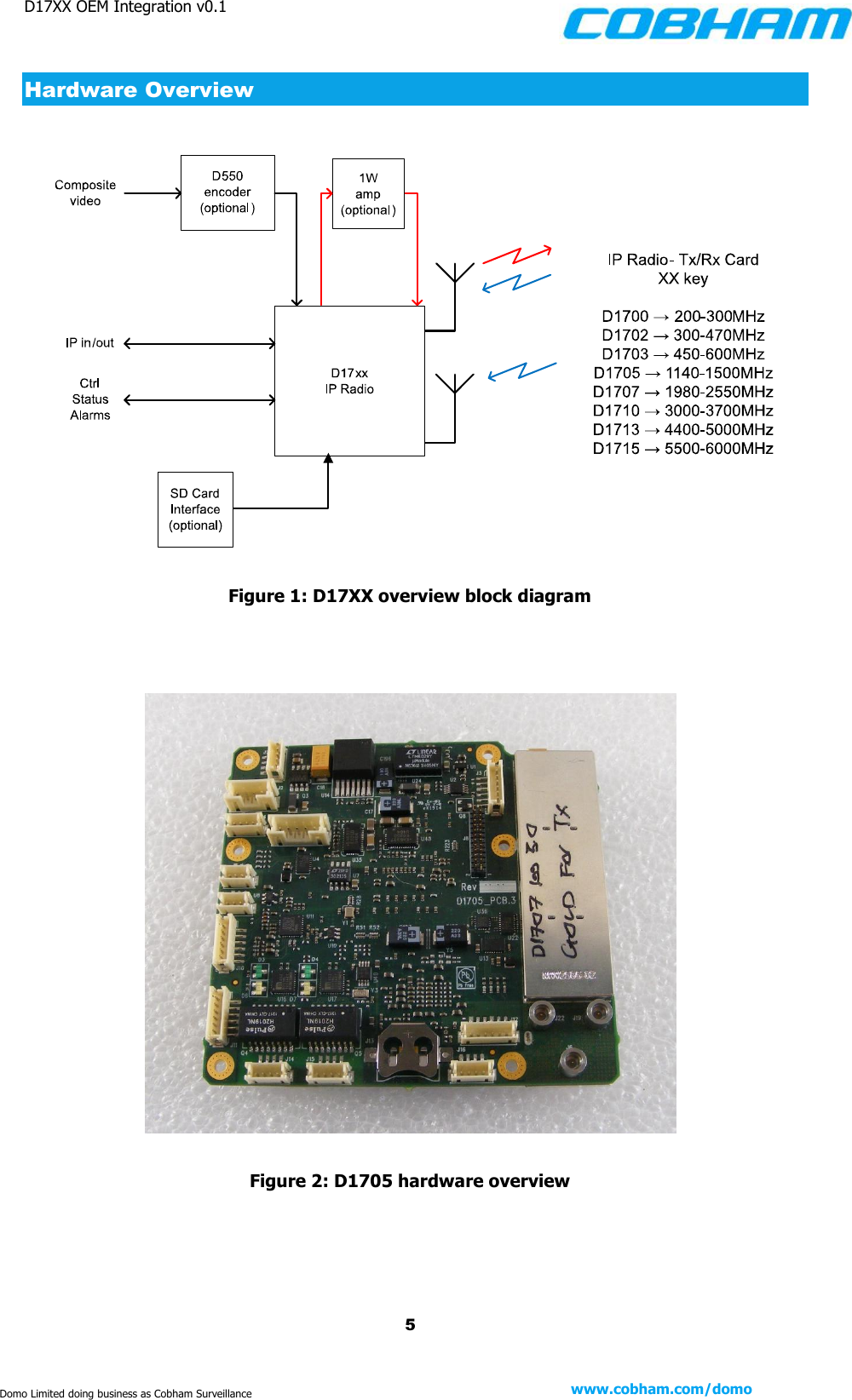
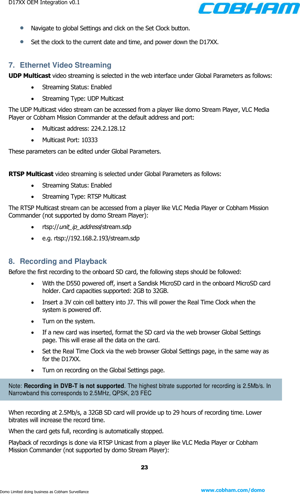
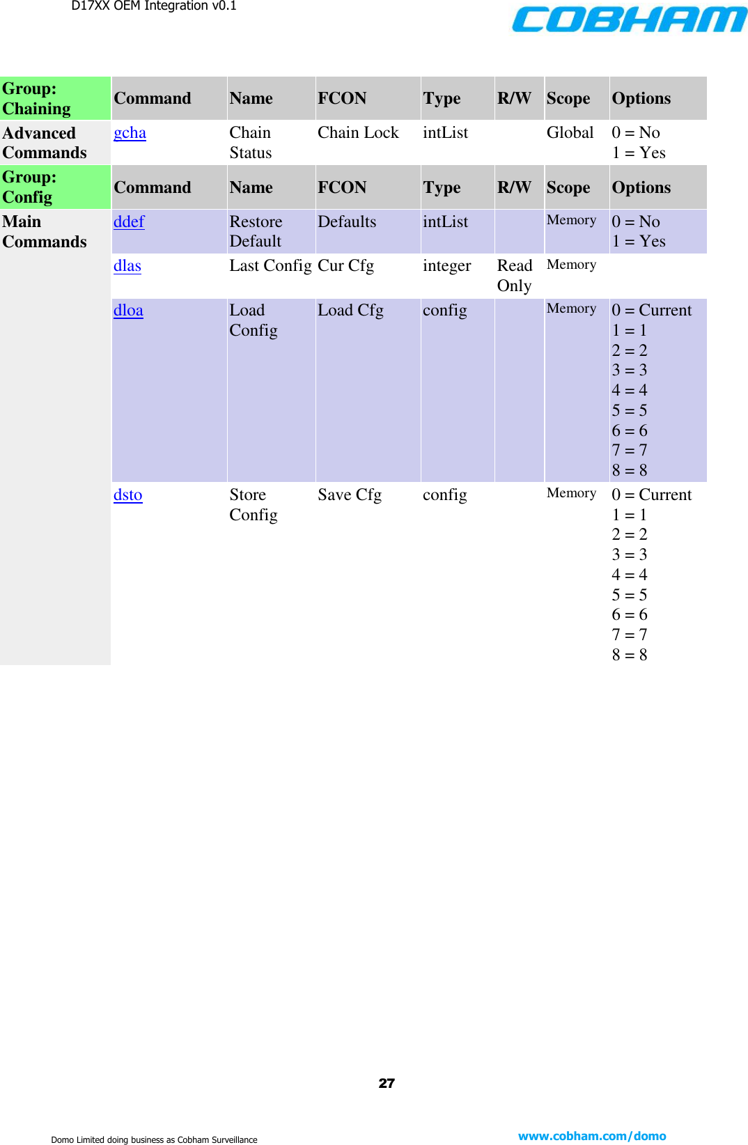
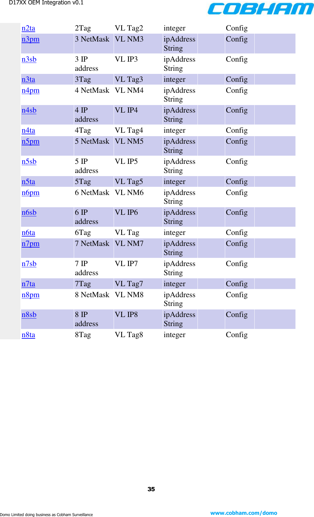
![D17XX OEM Integration v0.1 7 www.cobham.com/domo Domo Limited doing business as Cobham Surveillance PCB Variants The frequency selection is provided by the choice of RF card and setting the unit type on the D17XX. Table 1: D17XX variants (without screen cans) A number of the boards are available in top-level assemblies. Table 2: Sub-assemblies featuring D17XX parts (with screen cans) Product No. Frequency [MHz] D1700 200 – 300 D1702 300 – 470 D1703 450 – 600 D1705 1140 – 1500 D1707 1980 – 2550 D1710 3000 – 3700 D1713 4400 – 5000 D1715 5500 – 6000 Cobham SA Number Description SA3024 D1707 OEM AGILE IP MESH, Mk4 (S Band 1.98-2.55GHz) Top Level Assembly SA3245 D1705 OEM AGILE IP MESH, Mk4 (L Band 1.14 - 1.5GHz) Top Level Assembly SA3334 D1705_D DSTAR OEM Agile IP MESH, MK4 (L Band) Top Level Assembly SA3453 D1703 OEM Agile IP MESH, MK4, 450-600MHz (UHF Band) Top Level Assembly SA3457 D1741 OEM Pavement RF Board (S Band 1.98-2.55GHz) Top Level Assembly](https://usermanual.wiki/Domo-Tactical-Communications/NETNODEP4.D17XX-OEM-INTEGRATION-DOC-V0-1/User-Guide-2940655-Page-7.png)
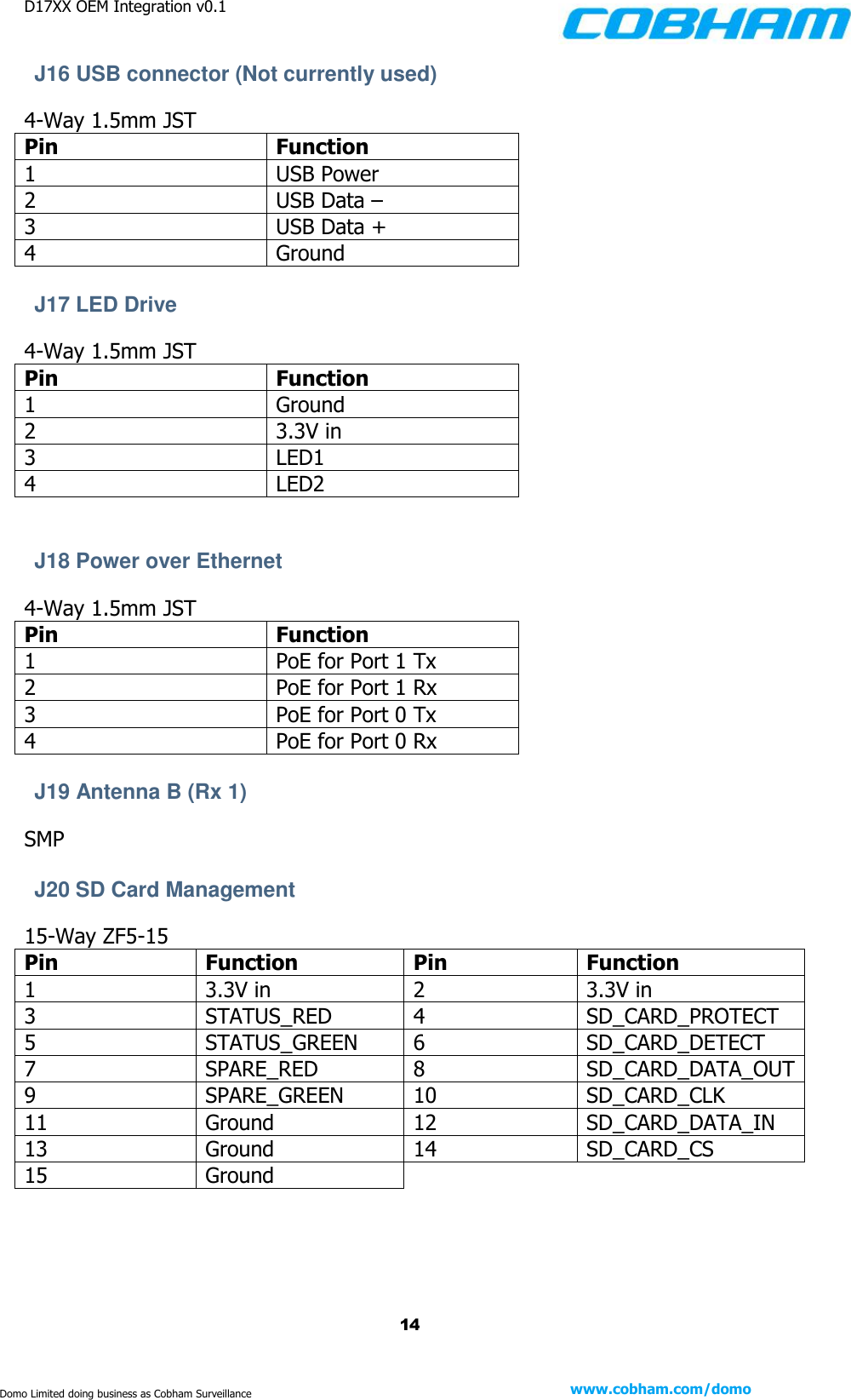
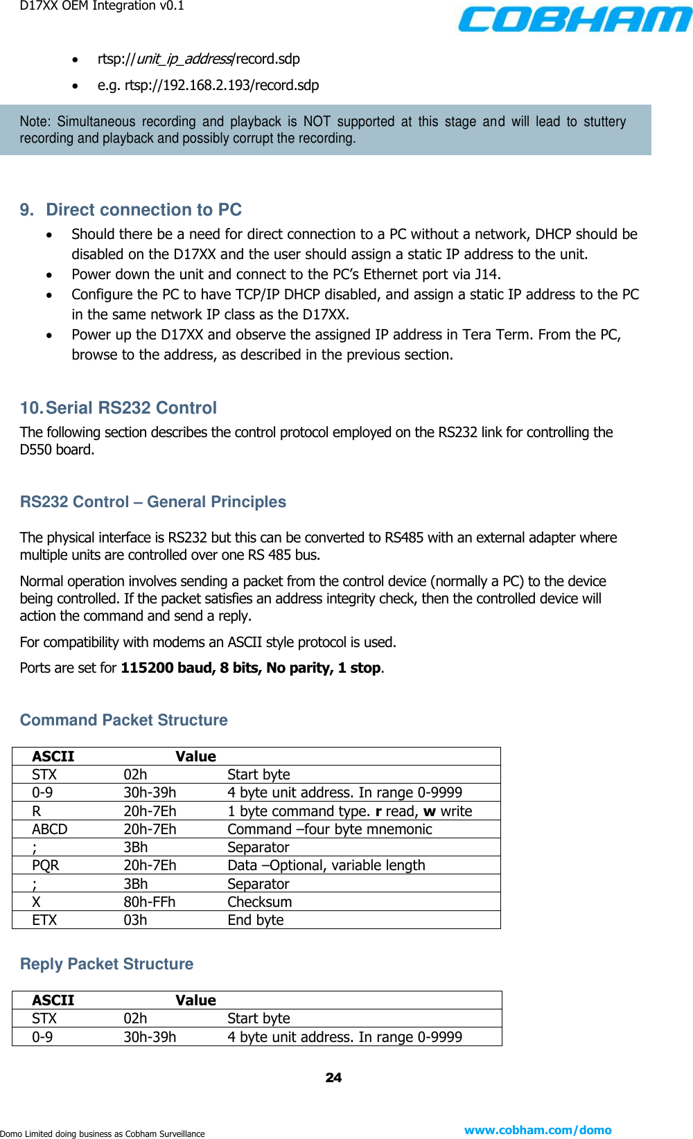
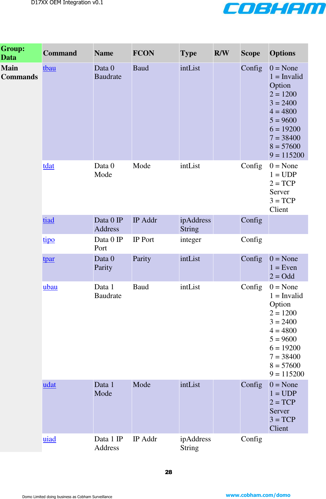
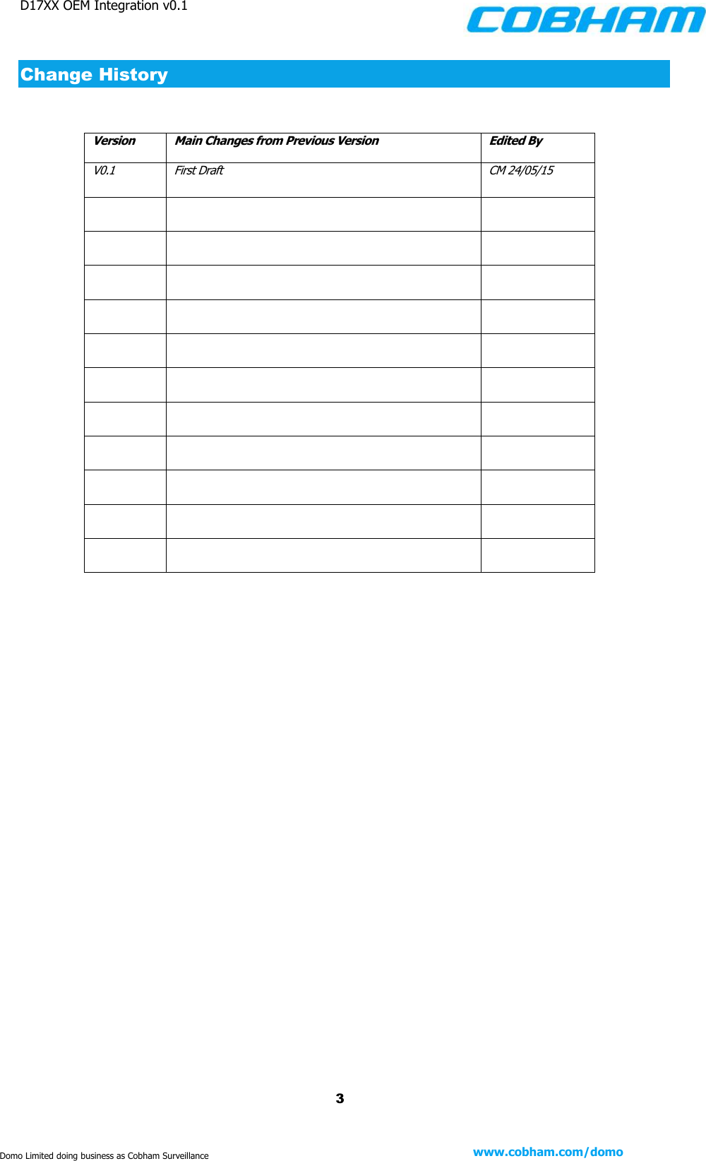
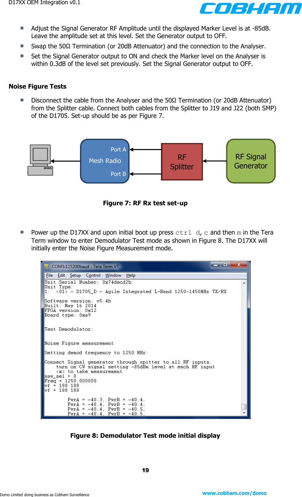
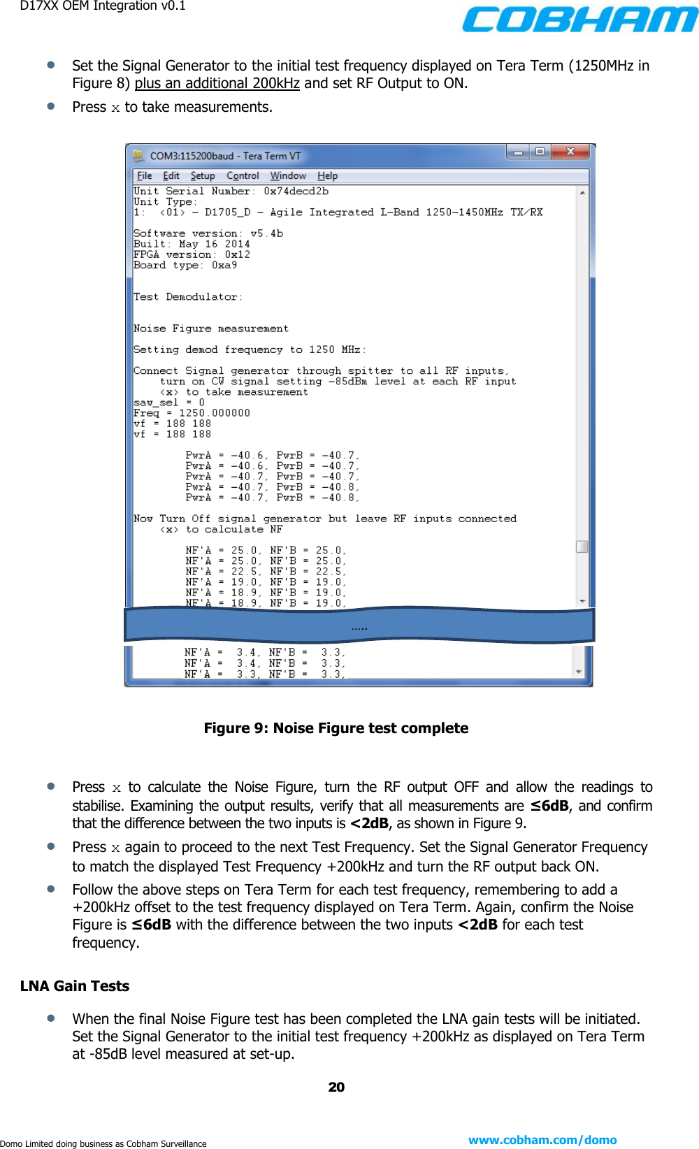
![D17XX OEM Integration v0.1 17 www.cobham.com/domo Domo Limited doing business as Cobham Surveillance Turning On the System [Extract taken from the D1705 TP v1.1 and as such, Tera Term figures will refer to this variant] 1. Test Setup Connect the following cables to the D17XX PCB, as shown in Figure 5. Power Cable from external PSU to J2 o Set supply to 12V 1.5A CA0364 to J14 (Connect Ethernet cable to CA0364 – not shown) CA0001/CA0149 to J12 If D550 encoder is desired (not shown): o D55x Custom loom to J4, J9, J11 o CA0186 to J7 on D576 Figure 5: Initial setup cabling 2. Initial Setup 2.1 Setting unit type Launch a Tera Term window and configure a serial port connection with the settings shown in Figure 6. Note that the port number will depend on your hardware setup and may well vary from that shown below.](https://usermanual.wiki/Domo-Tactical-Communications/NETNODEP4.D17XX-OEM-INTEGRATION-DOC-V0-1/User-Guide-2940655-Page-17.png)
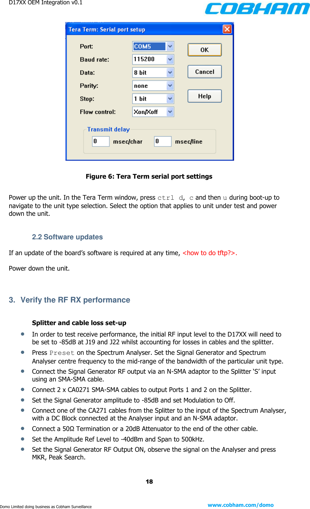
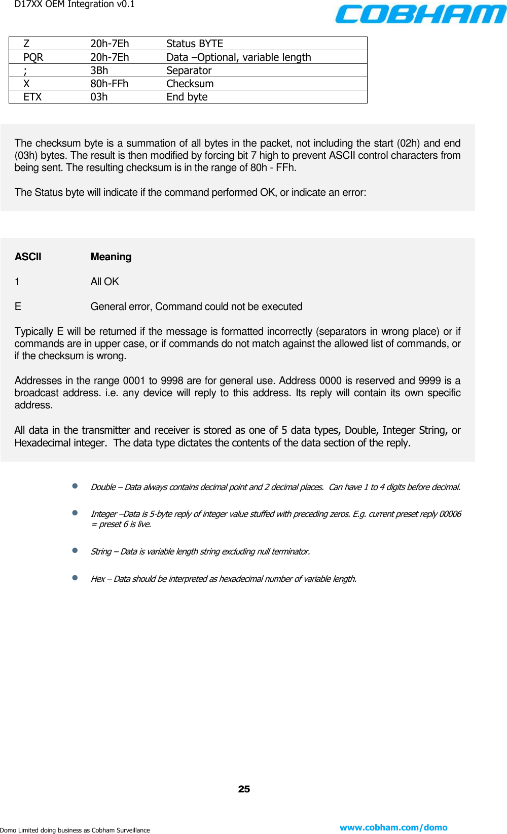
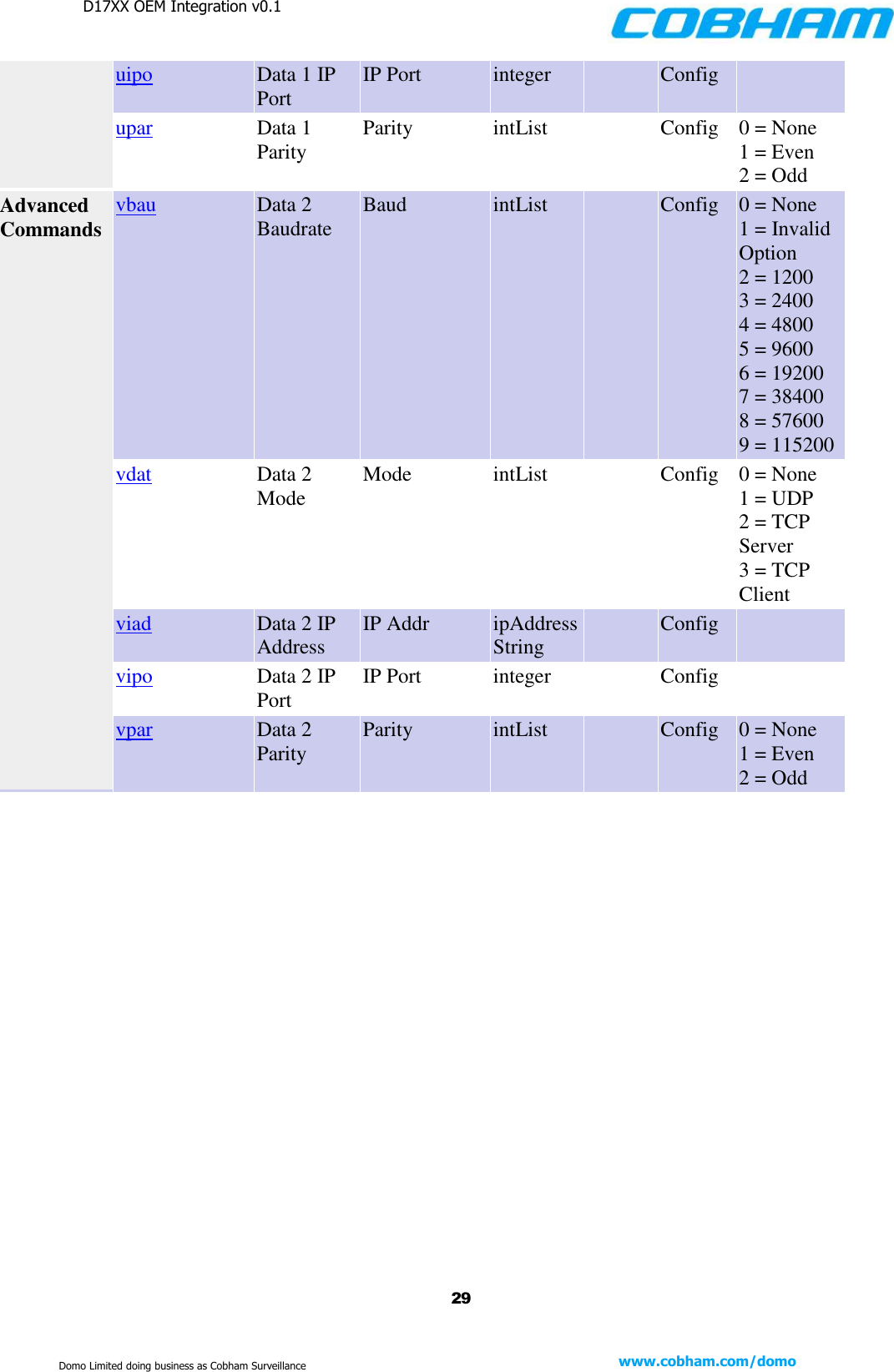
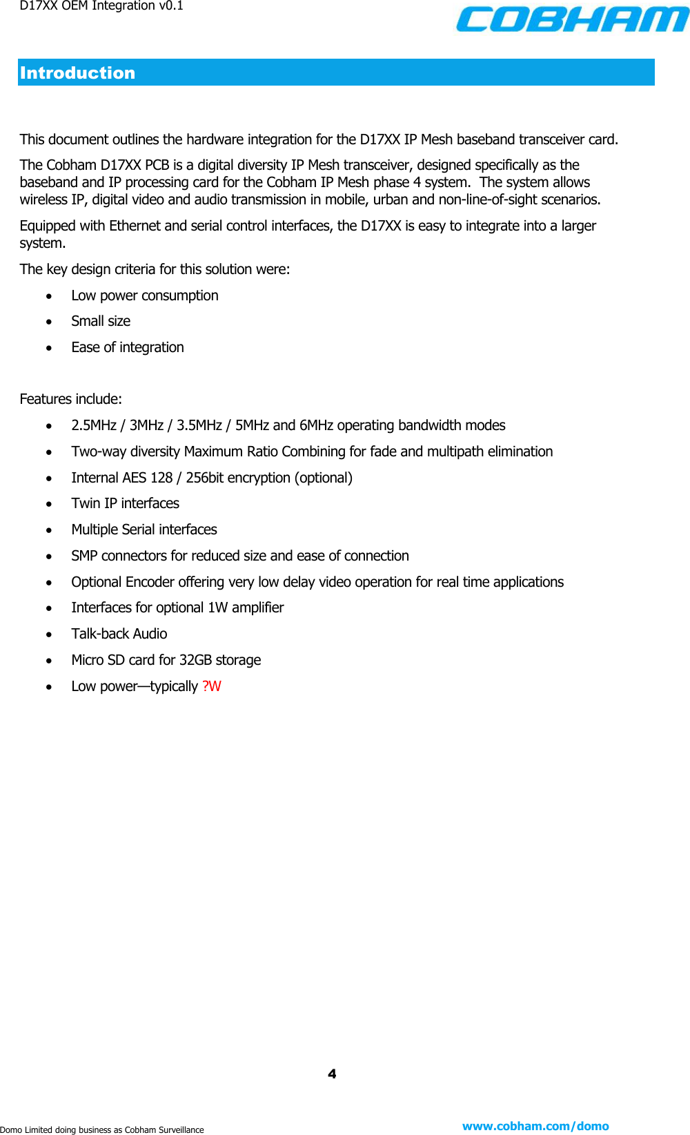
![D17XX OEM Integration v0.1 21 www.cobham.com/domo Domo Limited doing business as Cobham Surveillance Set the RF output of the Signal Generator to ON and verify the gain lies within the limits laid out in Table 3. Table 3: LNA gain limits Press x to continue through to the next gain frequency, remembering to add 200kHz to all indicated test frequencies on the Signal Generator and refer to Table 3 to verify the limits. Continue this process for all gain test frequencies. Press x to complete the LNA Gain Tests and turn the Signal Generator RF output OFF. 4. Verify the RF TX performance Plug in the RF cable to a Power Meter via the RF output (J24) on the D17XX. Cycle the power on the unit and upon initial boot up ctrl d, c and then t to enter power test mode, as shown in Figure 10. Figure 10: Power calibration display in Tera Term Frequency [MHz] Max Gain [dB] Min Gain [dB] 1250 -22 -27 1340 -19 -24 1400 -20.5 -25.5 1450 -23 -28](https://usermanual.wiki/Domo-Tactical-Communications/NETNODEP4.D17XX-OEM-INTEGRATION-DOC-V0-1/User-Guide-2940655-Page-21.png)