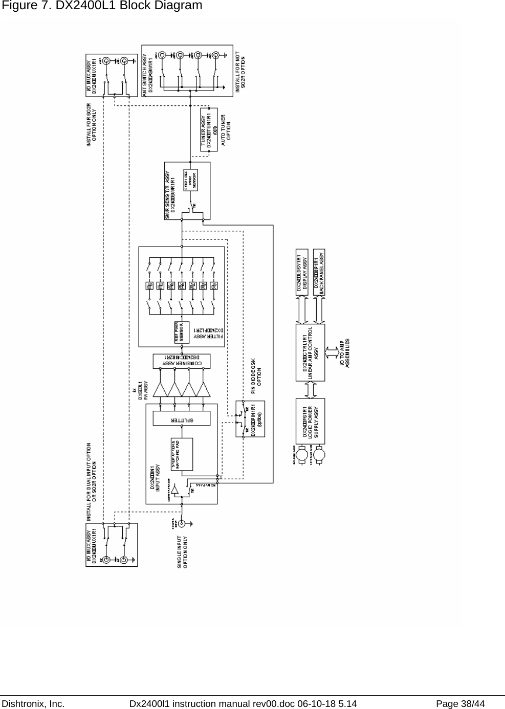
Dishtronix 2400L1 DX2400L1 HF Linear Amplifier User Manual users manual

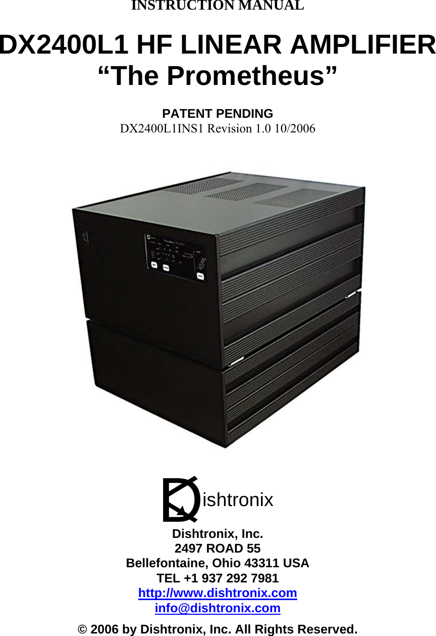
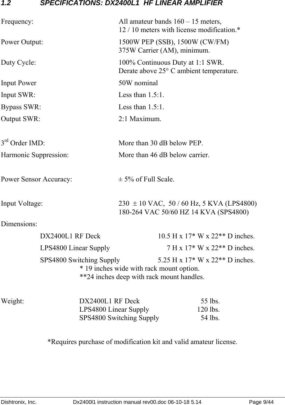
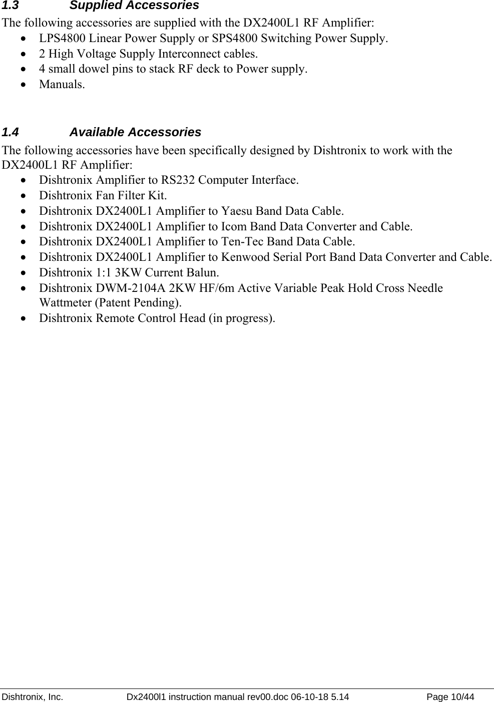
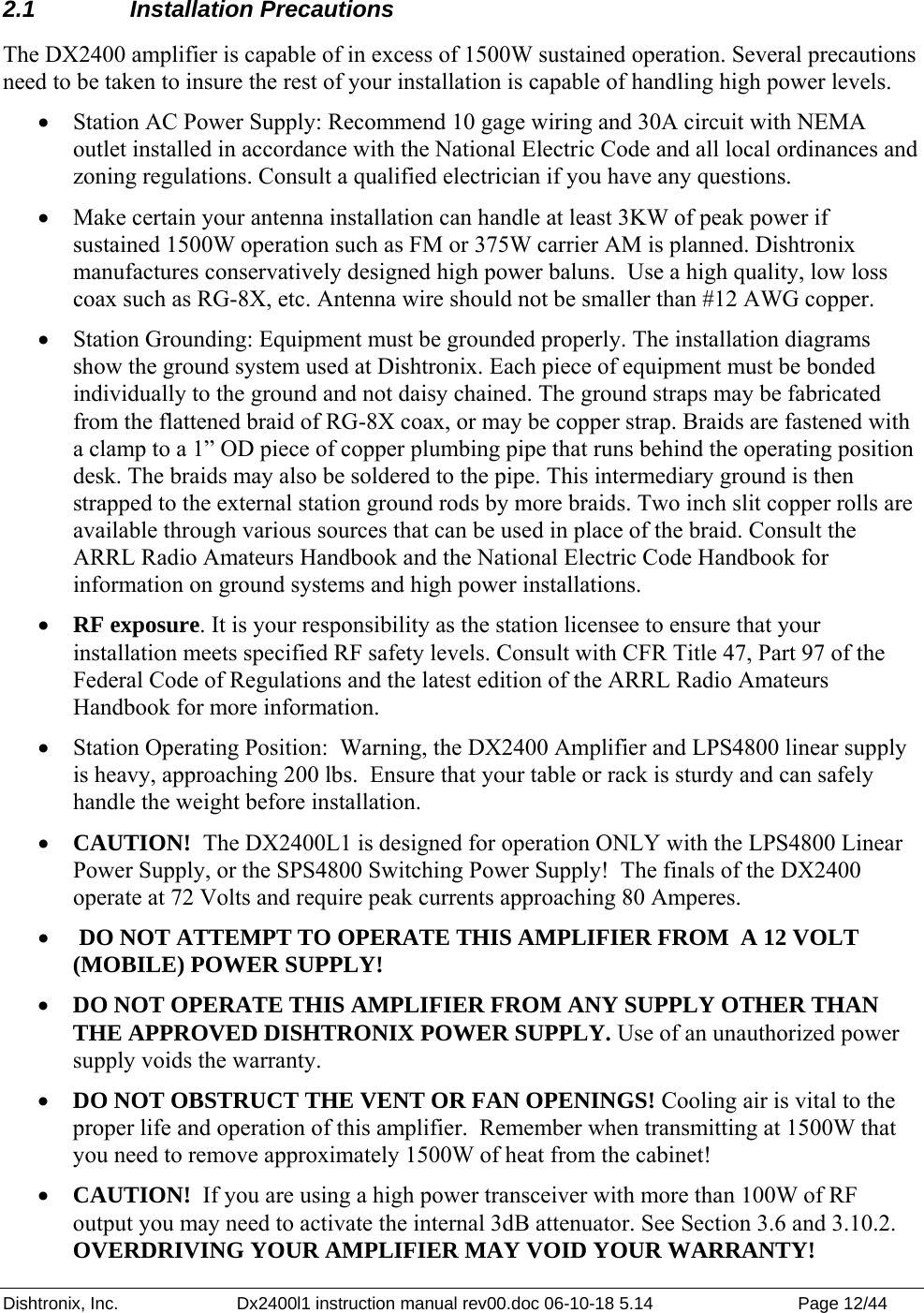
Dishtronix, Inc. DX2400L1 HF Linear Amplifier users manual

users manual

   INSTRUCTION MANUAL  DX2400L1 HF LINEAR AMPLIFIER “The Prometheus”  PATENT PENDING DX2400L1INS1 Revision 1.0 10/2006   Dishtronix, Inc. 2497 ROAD 55 Bellefontaine, Ohio 43311 USA TEL +1 937 292 7981 http://www.dishtronix.com info@dishtronix.com © 2006 by Dishtronix, Inc. All Rights Reserved. Dishtronix
Dishtronix, Inc.  Dx2400l1 instruction manual rev00.doc 06-10-18 5.14  Page 2/44              Printed in the United States of America Copyright 2006 by Dishtronix, Inc. ALL RIGHTS RESERVED No part of this document may be copied, reproduced, transmitted or used without the express written consent of Dishtronix, Inc.   Information, theory, techniques, processes, features and technology featured in this manual may be covered by one or more pending U.S. patents.
Dishtronix, Inc.  Dx2400l1 instruction manual rev00.doc 06-10-18 5.14  Page 3/44   ______________________________________________________________________________ October 18, 2006  Dear Valued Customer,  Thank you for purchasing your new DX2400L1 Amplifier. It is my most sincere hope that you will be 100 percent completely satisfied with your new amplifier.  This amplifier exists today because I could not purchase a solid state amplifier that was both legal limit and durable. The Prometheus represents 7 long years of full time research and development which I have personally conducted and supervised. The result is the first solid state amplifier commercially produced for the Amateur Service capable of 100% full duty cycle at the legal limit of 1500W. Each circuit board inside this unit has been personally designed by me to be assembled in house at Dishtronix to give you the ultimate service, performance, life, reliability and quality levels. The Dishtronix mission is to be the innovation and quality leader in both the solid state high power market and in customer satisfaction. Dishtronix was first to demonstrate continuous key 1500W CW the entire weekend of the 2004 and 2005 Dayton Hamvention.  Your purchase and support insures that Dishtronix will be able to continue its pioneering efforts in the HF solid state high power arena. I know there are some other solid state units coming along. Please set my unit side by side with theirs and transmit 1500W into the dummy load with a brick on the key. Which unit appears to you to be purposely over designed? If your life depended on having an amplifier, which one would you prefer?  If you need more persuasion, twist the drive knob to the right! Dishtronix products are not the least expensive because I do not ever cut corners off of lifetime or performance just to save a few dollars. In fact, I use the best components that I can buy without regard to cost. If good enough components don’t exist I make them or have them made. I know that you, my valued customer, expect more, which is why I can personally stand behind every DX2400L1 amplifier that I sell and why I am proud to put my name on my company. The DX2400L1 is built simply to be the best. If you have any problems with this unit, please do not hesitate to contact me directly. If there is anything I can do to make your Dishtronix amplifier experience more positive, please let me know.  Thank you again for your valued business.  Sincerely,  Steven M. (Mike) Dishop, N8WFF President, Dishtronix, Inc. “Dishtronix Solid Power ™ Anywhere, Anytime, Anyplace”. MADE IN USA PATENTS PENDING Designed and Manufactured in the United States of America by a 100% American owned company. Dishtronix
Dishtronix, Inc.  Dx2400l1 instruction manual rev00.doc 06-10-18 5.14  Page 4/44   TABLE OF CONTENTS 1.  INTRODUCTION...................................................................................................................7 1.1  DX2400L1 RF Deck Features..........................................................................................8 1.2  SPECIFICATIONS: DX2400L1  HF LINEAR AMPLIFIER .........................................9 1.3 Supplied Accessories......................................................................................................10 1.4 Available Accessories ....................................................................................................10 2.   INSTALLATION...............................................................................................................11 2.1 Installation Precautions ..................................................................................................12 2.2 Unpacking ......................................................................................................................13 2.3  HV DC Supply Verification ...........................................................................................13 2.4  Mounting RF Deck on Top of Power Supply.................................................................14 2.5  Full Break In QSK..........................................................................................................14 2.6  Semiautomatic Break In .................................................................................................14 2.7  PTT QSK Operation.......................................................................................................15 3. OPERATION .........................................................................................................................19 3.1  Front Panel Controls.......................................................................................................21 3.2  Rear Panel Controls and Connectors..............................................................................22 3.3  Connector Pin Definitions..............................................................................................25 3.4  +12V IN Jack..................................................................................................................26 3.5  Auto Power On Feature..................................................................................................26 3.6 Programming Mode........................................................................................................26 3.7 Band Selection................................................................................................................27 3.7.1  Automatic Band Selection (Default) ......................................................................27 3.7.2  Manual Band Selection ..........................................................................................27 3.7.3  Band Selection with Internal Frequency Counter ..................................................27 3.8  Band Data Hardware Interface .......................................................................................28 3.9 ALC ................................................................................................................................28 3.9.1   ALC Indicator.........................................................................................................29 3.9.2   ALC-SWR Foldback ..............................................................................................29 3.9.3   ALC Adjustment Procedure ...................................................................................29 3.9.4   ALC Irregularities ..................................................................................................30 3.10 Protection Features.........................................................................................................30
Dishtronix, Inc.  Dx2400l1 instruction manual rev00.doc 06-10-18 5.14  Page 5/44   3.10.1   SWR Protection......................................................................................................31 3.10.2   Overdrive  Protection .............................................................................................31 3.10.3   Over Current Protection .........................................................................................31 3.10.4   Power Supply Over Voltage Protection .................................................................31 3.10.5   Power Supply Under Voltage Lockout ..................................................................32 3.10.6   Over Temperature Protection .................................................................................32 3.10.7   Combiner Failure Fault ..........................................................................................32 3.10.8   T/R Failure Fault ....................................................................................................32 3.10.9   Error Status Display ..............................................................................................32 3.10.10   Clearing Fault Conditions ..................................................................................33 3.11 Remote Interface ............................................................................................................34 3.11.01   Interface Termination Resistors .........................................................................34 3.11.02   Interface Line Bias .............................................................................................35 3.11.03   Setting Remote Interface Power Options ...........................................................35 4.   THEORY OF OPERATION ..............................................................................................37 4.1   Block Diagram ...............................................................................................................39 4.2   Amplifier Circuitry Overview........................................................................................39 5.0 SERVICE ...........................................................................................................................41 5.1 Maintenance ...................................................................................................................42 5.1.1  Optional Rear Fan Filters .......................................................................................42 5.1.2  External Appearance and Care...............................................................................42 5.1.3 Fan Replacement ....................................................................................................42 5.2 Factory Service...............................................................................................................43 NOTES ...........................................................................................................................................44 TABLE OF FIGURES Figure 1. DX2400 Typical Installation with QSK Full Loop Keying......................................16 Figure 2. Typical Installation for Non-QSK Keying (Vintage) Transceiver..........................17 Figure 3. QSK Installation using Non-QSK Transceiver and External Keyer ....................18 Figure 4.  Front Panel Features ................................................................................................20 Figure 5. Rear Panel Controls and Connectors......................................................................24 Figure 6. Connector Pin Definitions..........................................................................................24 Figure 7. DX2400L1 Block Diagram .........................................................................................38
Dishtronix, Inc.  Dx2400l1 instruction manual rev00.doc 06-10-18 5.14  Page 6/44    This page left intentionally blank.
Dishtronix, Inc.  Dx2400l1 instruction manual rev00.doc 06-10-18 5.14  Page 7/44   1.  INTRODUCTION      About the name…… According to Greek mythology, Prometheus gave fire to man.  In retaliation, Zeus (the King of the Gods) chained him to a rock where every day an eagle ate his liver, and each night it magically grew back. Three thousand years later, this Prometheus puts legal limit fire in the wire, and sports a battery of technological features to prevent it’s guts from being blown out!  No Compromise HF Performance from Dishtronix.
Dishtronix, Inc.  Dx2400l1 instruction manual rev00.doc 06-10-18 5.14  Page 8/44   1.1  DX2400L1 RF Deck Features The DX2400L1 RF Amplifier incorporates a number of innovative and useful features: • Fully Automatic Band Switching: The DX-2400L1can be controlled (optional converter may be required) with the transceivers band data through CAT style optically isolated interface.  • For older transceivers without band data, the DX-2400L can sample the incoming RF drive and determine the proper band of operation under microprocessor supervision.  • Four Position Antenna Switch with automatic memory for last antenna used for each band. • Optically Isolated RS422 / RS485 remote interface allows operation up to 1500 feet away through one or two twisted cable pair with optional PC adapter and software package or optional remote control head.  • Optically isolated remote on capability from transceiver +12V Auxiliary jack. • ALC: Negative going from 0 to negative 10 Volts, adjustable. SWR-ALC foldback protection. • SWR overprotection circuit. Over temperature warning and shutdown protection. Over /under voltage lockout protection. Overdrive protection. Hardware failure protection (combiner balance, PIN T/R failure) • Digital bargraph for Forward Power, Reflected Power and True (computed) SWR. • PTT or selectable Full Loop QSK Keying to interlock transceiver and amplifier. • Vacuum antenna relay as standard equipment. PIN diode T/R switch available as an option. • FLASH Microprocessor allows field upgrades of amplifier firmware. • Separate low voltage control transformer for bias and microprocessor circuits reduces power consumption in continuous standby mode and allows metering of transceiver when in bypass mode.   • Full optic isolation of all control functions (Key In, Key Out, PTT, Band Data, Remote On) from transceiver as well as full optic isolation of computer /remote interface port. • 2400W PEP total dissipation rating of RF power transistors means conservative design with plenty of headroom • Low Pass Filters constructed with 12 gage coils and custom high power capacitors. • Oversize (30 lb) heat exchanger and 4 thermostatically controlled, ball bearing, variable speed cooling fans mounted in push – pull configuration for redundancy.
Dishtronix, Inc.  Dx2400l1 instruction manual rev00.doc 06-10-18 5.14  Page 9/44   1.2  SPECIFICATIONS: DX2400L1  HF LINEAR AMPLIFIER  Frequency:  All amateur bands 160 – 15 meters, 12 / 10 meters with license modification.* Power Output:    1500W PEP (SSB), 1500W (CW/FM)       375W Carrier (AM), minimum. Duty Cycle:      100% Continuous Duty at 1:1 SWR.          Derate above 25° C ambient temperature. Input Power   50W nominal Input SWR:      Less than 1.5:1.    Bypass SWR:    Less than 1.5:1.   Output SWR:     2:1 Maximum.  3rd Order IMD:    More than 30 dB below PEP.  Harmonic Suppression:    More than 46 dB below carrier.  Power Sensor Accuracy:    ± 5% of Full Scale.  Input Voltage:    230  ± 10 VAC,  50 / 60 Hz, 5 KVA (LPS4800)       180-264 VAC 50/60 HZ 14 KVA (SPS4800) Dimensions:  DX2400L1 RF Deck    10.5 H x 17* W x 22** D inches.    LPS4800 Linear Supply         7 H x 17* W x 22** D inches. SPS4800 Switching Supply  5.25 H x 17* W x 22** D inches. * 19 inches wide with rack mount option. **24 inches deep with rack mount handles.  Weight:    DX2400L1 RF Deck      55 lbs.     LPS4800 Linear Supply  120 lbs.      SPS4800 Switching Supply     54 lbs.  *Requires purchase of modification kit and valid amateur license.
Dishtronix, Inc.  Dx2400l1 instruction manual rev00.doc 06-10-18 5.14  Page 10/44   1.3 Supplied Accessories The following accessories are supplied with the DX2400L1 RF Amplifier: • LPS4800 Linear Power Supply or SPS4800 Switching Power Supply. • 2 High Voltage Supply Interconnect cables. • 4 small dowel pins to stack RF deck to Power supply. • Manuals.  1.4 Available Accessories The following accessories have been specifically designed by Dishtronix to work with the DX2400L1 RF Amplifier: • Dishtronix Amplifier to RS232 Computer Interface. • Dishtronix Fan Filter Kit. • Dishtronix DX2400L1 Amplifier to Yaesu Band Data Cable. • Dishtronix DX2400L1 Amplifier to Icom Band Data Converter and Cable. • Dishtronix DX2400L1 Amplifier to Ten-Tec Band Data Cable. • Dishtronix DX2400L1 Amplifier to Kenwood Serial Port Band Data Converter and Cable. • Dishtronix 1:1 3KW Current Balun. • Dishtronix DWM-2104A 2KW HF/6m Active Variable Peak Hold Cross Needle Wattmeter (Patent Pending). • Dishtronix Remote Control Head (in progress).
Dishtronix, Inc.  Dx2400l1 instruction manual rev00.doc 06-10-18 5.14  Page 11/44   2.   INSTALLATION
Dishtronix, Inc.  Dx2400l1 instruction manual rev00.doc 06-10-18 5.14  Page 12/44   2.1 Installation Precautions The DX2400 amplifier is capable of in excess of 1500W sustained operation. Several precautions need to be taken to insure the rest of your installation is capable of handling high power levels. • Station AC Power Supply: Recommend 10 gage wiring and 30A circuit with NEMA outlet installed in accordance with the National Electric Code and all local ordinances and zoning regulations. Consult a qualified electrician if you have any questions. • Make certain your antenna installation can handle at least 3KW of peak power if sustained 1500W operation such as FM or 375W carrier AM is planned. Dishtronix manufactures conservatively designed high power baluns.  Use a high quality, low loss coax such as RG-8X, etc. Antenna wire should not be smaller than #12 AWG copper. • Station Grounding: Equipment must be grounded properly. The installation diagrams show the ground system used at Dishtronix. Each piece of equipment must be bonded individually to the ground and not daisy chained. The ground straps may be fabricated from the flattened braid of RG-8X coax, or may be copper strap. Braids are fastened with a clamp to a 1” OD piece of copper plumbing pipe that runs behind the operating position desk. The braids may also be soldered to the pipe. This intermediary ground is then strapped to the external station ground rods by more braids. Two inch slit copper rolls are available through various sources that can be used in place of the braid. Consult the ARRL Radio Amateurs Handbook and the National Electric Code Handbook for information on ground systems and high power installations. • RF exposure. It is your responsibility as the station licensee to ensure that your installation meets specified RF safety levels. Consult with CFR Title 47, Part 97 of the Federal Code of Regulations and the latest edition of the ARRL Radio Amateurs Handbook for more information. • Station Operating Position:  Warning, the DX2400 Amplifier and LPS4800 linear supply is heavy, approaching 200 lbs.  Ensure that your table or rack is sturdy and can safely handle the weight before installation. • CAUTION!  The DX2400L1 is designed for operation ONLY with the LPS4800 Linear Power Supply, or the SPS4800 Switching Power Supply!  The finals of the DX2400 operate at 72 Volts and require peak currents approaching 80 Amperes. •  DO NOT ATTEMPT TO OPERATE THIS AMPLIFIER FROM  A 12 VOLT (MOBILE) POWER SUPPLY!  • DO NOT OPERATE THIS AMPLIFIER FROM ANY SUPPLY OTHER THAN THE APPROVED DISHTRONIX POWER SUPPLY. Use of an unauthorized power supply voids the warranty. • DO NOT OBSTRUCT THE VENT OR FAN OPENINGS! Cooling air is vital to the proper life and operation of this amplifier.  Remember when transmitting at 1500W that you need to remove approximately 1500W of heat from the cabinet! • CAUTION!  If you are using a high power transceiver with more than 100W of RF output you may need to activate the internal 3dB attenuator. See Section 3.6 and 3.10.2. OVERDRIVING YOUR AMPLIFIER MAY VOID YOUR WARRANTY!
Dishtronix, Inc.  Dx2400l1 instruction manual rev00.doc 06-10-18 5.14  Page 13/44    2.2 Unpacking First refer to the Power Supply manual for installation and set up of your power supply if you have not already done so. Carefully uncrate the DX2400L1 Amplifier RF deck. Save the packing for future use should it be required. Two identical 8 pin HV DC Power Cables, a 6 pin Control Interconnect Cable and four small dowel pins should be included in the package.  2.3  HV DC Supply Verification After installing your AC power plug on the AC supply cable according to the instructions in the power supply manual, the DC supply voltage should be checked.   1. Connect the amplifier deck and power supply together with the 6 pin control cable. Do not connect the 8 pin HV DC cables at this time.  2. The RF amplifier front panel power switch should be in the OFF position.  3. Connect the AC power line to the AC mains supply.  4. Connect a voltmeter across the HV supply pins.* (Refer to power supply manual) 5. Turn the front panel switch on. The amplifier front panel lights should come on.  6. Press the front panel BYPASS switch to activate the contactor in the LPS/SPS4800 Power Supply. A loud click should be heard.  7. After allowing 30 seconds for the voltage to stabilize, the supply voltage should measure between 70 - 80 volts on the voltmeter. Record the supply voltage here: __________. 8. Switch the amplifier front panel power switch off. 9. Remove the Control Interconnect Cable. 10. Unplug the power supply from the AC mains.  If the DC supply voltage is significantly high or low, the line voltage tap inside the LPS4800 may need set to a lower position or the internal voltage adjustments on the SPS4800 may need reset. . Refer to the appropriate Power Supply manual for more details.   *Note that if using the SPS4800 Switching Power Supply that each pin of the HVDC connector needs to be checked. Consult the SPS4800 Switching Power Supply for more information.
Dishtronix, Inc.  Dx2400l1 instruction manual rev00.doc 06-10-18 5.14  Page 14/44   2.4  Mounting RF Deck on Top of Power Supply The RF deck may be mounted on top of the Power Supply if desired. There are two small dowel pins included in the package. Fit two of these pins into the top center hole of two of the four metal feet mounted on top of the power supply. It is best to place one pin diagonally from the other.  Next, with a helper, lift the RF deck and place carefully over the power supply, guiding the feet of the RF deck over the pins so that the RF deck drops into place and will not slide off of the power supply. Now you may attach the two HV DC power cables, the control interconnect cable, the ground straps and other interconnecting lines to the exciter such as ALC, PTT, etc.  Refer to the following discussion of Loop Keying and Break In Operation to determine correct installation for your particular transceiver.  2.5  Full Break In QSK {Operation with Modern Transceivers that use Full Loop Keying} Some modern transceivers feature full loop keying circuitry.  The idea behind full loop keying is to correctly sequence the external power amplifier so that it is switched in line BEFORE the transmitter is keyed, and remains in line a short time AFTER the transmitter is unkeyed.  Figure 1 shows correct installation with a full loop keying transceiver.  With this type of installation there is no separate PTT line to the amplifier, so the amplifier front panel QSK key control should always be activated regardless of the exciter mode. The transceiver signals the amplifier to place itself in transmit mode through the exciter’s KEY OUT line which is connected to the amplifier KEY IN connector.  When the amplifier is placed in QSK mode, whenever the transceiver pulls this line to ground the amplifier will activate its internal antenna changeover relays. When the amplifier is ready to transmit, it will signal the exciter to produce RF by pulling the amplifier KEY OUT line to ground. This line is connected to the exciter KEY IN line. When the key is released, the exciter should quit producing RF and release the exciter KEY IN line. After a brief pause to insure no RF is flowing, the amplifier changes back to receive mode.  2.6  Semiautomatic Break In {Operation with Traditional Transceivers using PTT  (not Full Loop) Keying} It is possible to operate the exciter in a more traditional mode of operation where the transceiver simply activates the amplifier change over relay.  Figure 2 details installation of the amplifier with vintage or non-QSK transceivers.  For this installation the exciter PTT OUT line simply connects to the amplifier PTT IN jack.  The front panel QSK operation must be deactivated. When the transmitter is keyed, it signals the amplifier to come on line by pulling the PTT line to ground. The amplifier switched the antenna to the antenna output first to insure that the amplifier will not operate into an open circuit or hot switch the output relay. Once the antenna relay is activated, the amplifier switches the exciter output to the amplifier input. When the PTT line is released, the amplifier input relay is released, and then the amplifier antenna relay is released.
Dishtronix, Inc.  Dx2400l1 instruction manual rev00.doc 06-10-18 5.14  Page 15/44   2.7  PTT QSK Operation {QSK operation with Transceivers WITHOUT Full Loop Keying} It is possible to run QSK style operation with the amplifier using a non QSK or vintage exciter. Figure 3 details this installation.  For QSK operation connect the external straight key (or  external electronic keyer – Do not use the keyer inside the exciter!) directly to the amplifier KEY IN connector. Connect the amplifier KEY OUT line directly to the exciters CW KEY INPUT.  Note that the exciter PTT out line must be connected to the amplifier PTT IN line.  When using non QSK operation such as semi break in CW, SSB, AM, or FM modes, deactivate the amplifier front panel QSK mode and T/R operation will be as described in the SEMI AUTOMATIC BREAKIN paragraph above.  When CW operation is desired, activate the front panel QSK mode.  When the key is activated, the amplifier will sequence the T/R relays to the transmit position. The amplifier internal circuitry will delay the CW keying pulse a short period until the T/R relays are ready, and then pass the pulse to the amplifier KEY OUT line.  Since this line is connected to the exciter CW KEY jack, the exciter will go into transmit immediately and the amplifier will be ready.  When the key is released, the amplifier KEY OUT line is immediately released allowing the exciter to return to receive mode. The amplifier relays are held in the transmit position for a short time until RF quits flowing and then are released to the receive position.
Dishtronix, Inc.  Dx2400l1 instruction manual rev00.doc 06-10-18 5.14  Page 16/44    Figure 1. DX2400 Typical Installation with QSK Full Loop Keying
Dishtronix, Inc.  Dx2400l1 instruction manual rev00.doc 06-10-18 5.14  Page 17/44    Figure 2. Typical Installation for Non-QSK Keying (Vintage) Transceiver
Dishtronix, Inc.  Dx2400l1 instruction manual rev00.doc 06-10-18 5.14  Page 18/44    Figure 3. QSK Installation using Non-QSK Transceiver and External Keyer
Dishtronix, Inc.  Dx2400l1 instruction manual rev00.doc 06-10-18 5.14  Page 19/44   3. OPERATION
Dishtronix, Inc.  Dx2400l1 instruction manual rev00.doc 06-10-18 5.14  Page 20/44   Figure 4.  Front Panel Features
Dishtronix, Inc.  Dx2400l1 instruction manual rev00.doc 06-10-18 5.14  Page 21/44   3.1  Front Panel Controls Figure 4 details the front panel controls. A.  Power Switch – Activates internal low voltage supply for metering, logic and communications circuits.  B.  Antenna Select Indicators – Indicates which antenna is currently selected by the ANT switch (I). C.  Bypass Indicator – Indicates that amplifier is bypassed in the standby mode and that the high voltage supply has been disabled. Activated by the BYPASS (J) key or when a fault condition places the amplifier in protection mode. Blinks while high voltage supply charges up. May blink in conjunction with Error Status Indicators (D) for fault diagnosis readout. D.  Error Status Indicators – Indicates either individual conditions if not blinking, or other faults according to Chart in Section 3.10 if blinking.   1. SWR Indicator – Active if reflected power exceeds safe level.   2. DRIVE Indicator – Blinks whenever input power exceeds recommended drive level regardless of internal attenuator settings.  Continuously on as a latched fault condition whenever drive exceeds maximum safe input drive level.   Note – both indicators are latched on until the unit cools when over temperature. E.  ALC Indicator -  Illuminates as the generated ALC voltage begins to significantly depart from 0 volts negative. F.  QSK Indicator – Illuminated when Full Loop Keying mode is selected by QSK (K) switch. G.  AUTO Indicator – Illuminated whenever external rear panel BAND DATA signals are present, or when the frequency counter band selection mode is selected by the BAND (L) switch control.  H.  BAND Select Indicators -  Indicates which low pass filter has been selected by the external rear panel BAND DATA signals, if present, or by the internal frequency measuring circuit, if activated, or by the manual selection of the BAND (L) switch. I.  ANT Select Switch – used to select rear panel antenna for each band. Note that the selection is automatically stored for each setting of the BAND switch.  To select a different antenna depress the switch and cycle through the antennas by watching the antenna select indicator (B) J.  BYPASS Switch – used to toggle the amplifier in or out of line as indicated by the BYPASS Indicator (C). Press this switch to clear a fault condition such as SWR or Drive and place the amplifier back on line AFTER the cause of the fault has been determined and corrected.  K.  QSK Loop Keying Select Switch – used to select FULL LOOP KEYING, with amplifier transceive triggered by the back panel KEY IN jack, or PTT KEYING with the amplifier transceiver triggered by the back panel PTT IN jack.
Dishtronix, Inc.  Dx2400l1 instruction manual rev00.doc 06-10-18 5.14  Page 22/44   L.  BAND Select Switch – Used to manually select appropriate filter if no external signals are present on the rear panel BAND DATA connector, or used to select the internal frequency measuring circuit to automatically sample the incoming signal and select the correct filter when no BAND DATA is available from the transceiver. Note that presence of external BAND DATA overrides operation of the BAND switch and that frequency counter and manual band selection is not possible. For manual band selection depress the BAND select key and scroll through the bands as displayed on the front panel BAND Select Indicators (H). For internal frequency measuring mode depress and hold the BAND select Key for approximately 5 seconds until the front panel AUTO Band Indicator (G) illuminates. Frequency counter mode will be saved and active at power on until it is reset by the user.  3.2  Rear Panel Controls and Connectors Figure 5 details the rear panel controls and connectors. A. Cooling Fans – move cooling air through the cabinet. May be externally replaced by unplugging the supply cable from the rear panel FAN connector (M). Do not obstruct airflow to the fans! B. TRANSMITTER Input – RF input to the exciter or transceiver. Do not exceed 100W on this connector without activating the internal 3dB attenuator. C. TUN ADJ – this control is not used and is reserved for future expansion of the DX2400L1. D. ALC ADJ -  this control is used to set the ALC feedback level to the exciter. Refer to Section 3.9 to adjust this control. E. PS CTRL -  this connector caries control signals and 110VAC power for the internal low voltage control from the LPS4800 or SPS4800 Power Supply. See section 3.3 for pin information. F. DATA Connector -  this connector caries signals to interface the amplifier computer to external RS485 or RS422 interfaces. See section 3.3 for pin information. G. BAND DATA Connector -  this connector caries BAND data signals for automatic band switching from the exciter. ALC and Keying signals are also duplicated on this connector. See section 3.3 for pin information. H. +12V IN Connector -  this connector is typically connected to the exciter  switched +12V accessory output connector. This voltage is used to power the exciter side of the optically isolated interface functions (BAND DATA, PTT, KEY IN, KEY OUT, DATA). When +12V is applied, the amplifier front panel switch is bypassed and the amplifier low voltage and metering circuits are automatically switched. See section 3.4 and 3.5 for more information and configuration options. I. ALC OUT – this connector supplies the negative ALC feedback voltage to the exciter. J. KEY IN – this connector is used by the exciter to signal the amplifier to enter transmit mode when front panel QSK mode (FULL LOOP KEYING) is selected. If the front panel QSK mode is not selected, this connector has no effect on amplifier operation.
Dishtronix, Inc.  Dx2400l1 instruction manual rev00.doc 06-10-18 5.14  Page 23/44   K. KEY OUT – this connector is used by the amplifier to signal the exciter to begin transmitting once the amplifier is in transmit mode when front panel QSK mode (FULL LOOP KEYING) is selected. If the front panel QSK mode is not selected, this connector has no effect on amplifier operation. L. PTT IN -  this connector is used to place the amplifier in transmit mode for traditional or vintage transmitters that do not support full loop keying. Grounding this pin will place the amplifier in transmit mode when the front panel QSK mode is not selected. If QSK mode is selected, this connector is ignored and has no function or effect on amplifier operation. M. FANS -  this connector carries power to the cooling fans. Do not unplug this connector! N. ANTENNA 4 – this connector is selected by the front panel ANT switch. This connector has the poorest reflection at the high end of the band, so it should be used for the lowest frequency antenna, typically the 160m receiving loop. O. ANTENNA 3 – this connector is selected by the front panel ANT switch. This connector has slightly less reflection than ANTENNA 4, so it should be used for the second lowest frequency antenna, typically the 80m/40m parallel resonant dipole or inverted-vee antenna. P. ANTENNA 2 - this connector is selected by the front panel ANT switch. This connector has slightly less reflection than ANTENNA 3, so it should be used for the third lowest frequency antenna, typically the vertical 40m-10m vertical antenna. Q. ANTENNA 1 - this connector is selected by the front panel ANT switch. This connector has the best match of all antenna connectors, so it should be used for the highest frequency antenna, typically the 20m-10m multiband beam antenna. NOTE: When the amplifier is powered off, this antenna is jack is connected straight through to the rear panel  TRANSMITTER INPUT Jack (B) Hence the transceiver will use this antenna if the amplifier unit is not powered. R. GROUND -  this terminal is for grounding the equipment to the station ground. Do not daisy chain equipment ground together. See the Installation section for correct grounding procedures. S. PS HV1 – This connector carries the high voltage DC to internal power modules #1 and #2 from the LPS4800 or SPS4800 Power Supply. T. PS HV2 – This connector carries the high voltage DC to internal power modules #3 and #4 from the LPS4800 or SPS4800 Power Supply.
Dishtronix, Inc.  Dx2400l1 instruction manual rev00.doc 06-10-18 5.14  Page 24/44   Figure 5. Rear Panel Controls and Connectors
Dishtronix, Inc.  Dx2400l1 instruction manual rev00.doc 06-10-18 5.14  Page 25/44   3.3  Connector Pin Definitions Figure 6 details connector pin functions as viewed looking at the rear of the amplifier.  Figure 6. Connector Pin Descriptions PS CTRL    MALE    1 2 3 4 5 6 N L1 CONTACTOR-2 CONTACTOR-1 12 VAC 12 VAC RF deck internal AC supply 110VAC return. RF deck internal AC supply 110VAC. 110 VAC to PS Relay. 110 VAC PS Relay return. Optional 12V circuit from LPS4800. Optional 12V returnt from LPS4800. PS HV 1, 2    MALE  Note HV2=MOD3, 4.  1 2 3 4 5 6 7 8 GROUND #1 GROUND #2 GROUND #3 GROUND #4 HV SUPPLY #1  HV SUPPLY #2 HV SUPPLY #3 HV SUPPLY #4 Module 1 Supply Return. Module 1 Supply Return. Module 2 Supply Return. Module 2 Supply Return. Module 1 Supply 72V Source. Module 1 Supply 72V Source. Module 2 Supply 72V Source. Module 2 Supply 72V Source. BAND DATA    Mini DIN Female   1 2 3 4 5 6 7 8 9 10 11 12 13 BAND DATA D KEY IN ALC OUT +12V OUT BAND DATA C PTT IN KEY OUT +12V IN BAND DATA B BAND DATA A GROUND +12V OUT GROUND  Shared with back panel phono jack. Shared with back panel phono jack. Accessory power from internal supply  Shared with back panel phono jack. Shared with back panel phono jack. Shared with back panel phono jack.    Accessory power from internal supply.  DATA  RJ45-8 FEMALE   1 2 3 4 5 6 7 8 TX+ V+ RX+ RX- V- TX- SHIELD GROUND-COM RS422 TX+ Interface +SUPPLY Voltage RS422 RX+ / RS485+ RS422 RX- / RS485- Interface –SUPPLY Voltage RS422 TX- Communication cable shield. Communications system ground. Phono Jacks  1 2 SIGNAL GROUND Inner contact. Outer contact ring.
Dishtronix, Inc.  Dx2400l1 instruction manual rev00.doc 06-10-18 5.14  Page 26/44   3.4  +12V IN Jack The amplifier is completely optically isolated from the outside world, with the exception of the ALC line.  The amplifier is set at the factory so that power for the BAND DATA jack, as well as the remote interface is normally supplied from this port. This jack is normally connected to the transceiver +12V AUX line. Most transceivers switch the +12V AUX line off and on.  As configured at the factory, the amplifier turns on automatically whenever +12V is present at this jack. See the Auto Power On discussion section for more details.  3.5  Auto Power On Feature Whenever +12V is supplied to the rear panel +12V In jack, the front panel switch is overridden. The 12V signal activates an optically isolated triac which shorts the power switch to the ON position. This feature can be disabled by removing the 1KΩ resistor R1 on the Logic Power Supply PCB located behind the front panel. This feature allows the amplifier metering circuits to power up automatically when the transceiver is switched on. As shipped from the factory, the default power up condition for the amplifier is the bypass mode.  The default condition can be toggled to power up by entering the programming mode. See the programming mode section for more details.  3.6 Programming Mode The default power up state of the amplifier can be changed from the programming mode. • To enter the programming mode, turn off the transceiver and amplifier front panel switch. • Depress the ANT and BAND keys simultaneously, and turn the amplifier power switch to ON • To enable or disable a feature, depress the appropriate toggle key according to the chart below. • To exit the programming mode, turn the amplifier front panel switch off. • Allow a short pause, and reactivate the amplifier by either the transceiver remote on or the front panel switch.  The amplifier should come up in the new desired state. The following chart details different setting options for the program mode: Feature   Display LED  Illuminated  Extinguished   Toggle Key Power On State  BYPASS  Standby*  Operate  BYPASS QSK state  QSK  Loop keying  PTT keying*  QSK Interface mode  BAND AUTO  RS422*  RS485  BAND 200W attenuator  DRIVE  Active  Disabled*  ANT PIN T/R Enable  SWR  Installed  Bypassed  BAND+QSK * denotes  (default) settings as shipped from factory.
Dishtronix, Inc.  Dx2400l1 instruction manual rev00.doc 06-10-18 5.14  Page 27/44   Note that RS422 mode must be selected when updating the amplifier firmware (FLASH programming) over the interface! For example, consider that the BYPASS LED indicates the default power up condition. If it is illuminated, the default power up condition is bypass. If it is extinguished the amplifier will be on line immediately after power up with no user intervention. To toggle this setting, press the BYPASS key. The LED will indicate the new default setting. Simply shut the amplifier off when you are finished programming. The new states are saved to memory.  3.7 Band Selection The band data port is directly compatible with Yaesu transceivers. Icom transceivers require a converter available from Dishtronix.  Kenwood and other transceivers without band data may work with a Dishtronix adapter. Consult Dishtronix for technical assistance.  Whenever the amplifier senses anything other than high impedance (+5V) on the BDATA lines, the front panel BAND AUTO LED will be illuminated, and the BAND switch will have no action. Further, if an invalid BAND DATA word is sensed, the highest frequency band will be selected, the BAND AUTO LED will flash, the amplifier will enter BYPASS mode, and transmit will be disabled.  There are four methods of selecting the proper amplifier band: 1) Automatically via  rear panel BAND DATA connector. 2) From transceiver or PC via the RS485/422 interface rear panel DATA connector. 3) Manually from front panel BAND switch. 4) Semi automatically by sampling the input signal with internal frequency counter. (Note – manual selection is possible in this mode.) 3.7.1  Automatic Band Selection (Default) The amplifier will switch bands automatically when appropriate band data is applied to the BAND DATA connector.  Any connection to the  BAND DATA lines takes precedence over any other mode (interface, manual or semiautomatic). 3.7.2  Manual Band Selection If no connection is made to the band data port, the BAND switch on the front panel may be used to select the appropriate band of operation.  Alternatively, the band may be set over the remote interface. Refer to the Interface Programming Manual for further information. 3.7.3  Band Selection with Internal Frequency Counter If no connection is made to the band data port, the internal frequency counter may be enabled. This semiautomatic mode samples the incoming RF signal and selects the appropriate band of operation automatically. This is useful on older radios with no interface, or unsupported radios.   To engage the auto frequency detect mode, press and hold the BAND switch until the AUTO BAND LED is illuminated.  The band switch is still manually adjustable in this mode, and it is recommended that you preset the amplifier to the desired band of operation manually. Frequency
Dishtronix, Inc.  Dx2400l1 instruction manual rev00.doc 06-10-18 5.14  Page 28/44   counter mode will be saved and active at power on until it is reset by the user. To disable the feature, simply depress and hold the BAND switch until the AUTO BAND LED is extinguished.  3.8  Band Data Hardware Interface The four BAND DATA lines (BDATA_A, BDATA_B, BDATA_C,  BDATA_D) are completely optically isolated from the amplifier.  Power is derived from the +12V IN connector, normally connected to the transceiver AUX +12 jack for the interface operation.  The BAND DATA lines are +5V and require the transceiver to sink 15mA of current per line.   It is possible to change the BAND DATA interface to  an internally powered (independent of +12V IN jack, normally connected to transceiver +12V AUX jack), un-isolated interface Removing R179, a 0Ω 0805 SMD resistor (marked 000) from the DX2400CTRL Amplifier Control circuit board located behind the front panel, and installing a jumper wire at FB26 will power the interface from the internal logic supply. This modification is strongly discouraged.  The following chart details the BAND DATA lines and corresponding amplifier band selection: BAND   BDATA_D BDATA_C  BDATA_B BDATA_A 160m 0V  0V  0V  5V 80m 0V 0V 5V 0V 60/40m 0V  0V  5V  5V 30m 0V 5V 0V 0V 20m 0V 5V 0V 5V 17m 0V 5V 5V 0V 15m 0V 5V 5V 5V 12m* 5V  0V  0V  0V 10m* 5V  0V  0V  5V 6m** 5V  0V  5V  0V * Disabled on US models. May be enabled by licensed Amateurs. ** Disabled on DX2400L1.   3.9 ALC ALC is an acronym for Automatic Level Control, which is a system designed to feed back a  signal to the exciter in order to automatically reduce exciter drive power once full power output of the amplifier is achieved. ALC is desirable because it helps reduce overdriving of the amplifier on voice peaks and thereby helps keep the amplification linear. “Splatter” or adjacent channel interference is a typical symptom of an overdriven amplifier. ALC typically functions by outputting a negative going voltage from the amplifier back to the transceiver. The reason the ALC voltage is negative is a hangover from vacuum tube days when the amplifier grid current was rectified and fed back as a negative going signal to directly reduce bias on the exciter IF tubes.  Negative voltage ALC has no benefit over positive voltage in the
Dishtronix, Inc.  Dx2400l1 instruction manual rev00.doc 06-10-18 5.14  Page 29/44   modern solid state age, and in fact is an inconvenient cost adding feature. . The only reason for negative ALC is for industry compatibility. ALC is a difficult feature to implement on an amplifier designed to be used with many different transceivers. A problem exists because there is no standardized ALC voltage level or formula between different transceiver manufacturers. Some manufacturers even have different ALC levels on different model transceivers!  For example the ALC on a Kenwood TS-950SDX was found to be in the 0 to -7 V range, while a Kenwood TS570D was measured in the 0 to-9V range.  An Yaesu FT100 was found to be in the 0 to-2.5V range. Amplifiers manufactured by Dishtronix loosely follow, and Dishtronix proposes all manufacturers adopt, the following general ALC voltage relationship: OUTALC PV 51≅ Hence for 1500W output, the output ALC voltage is 7.75 Volts. The ALC ADJ adjustment potentiometer on the amplifier rear panel shifts this voltage up or down as necessary for your particular exciter. 3.9.1   ALC Indicator The front panel ALC indicator illuminates when the amplifier starts to significantly depart from 0V, indicating that it is generating ALC voltage. The illumination begins somewhere in the range of -0.7 to -1.0 Volt of ALC. 3.9.2   ALC-SWR Foldback Note that the ALC system is designed to generate significant ALC voltage whenever the reflected power exceeds approximately 200W (an SWR of about 2.1:1 with 1700W forward and 200W reflected).  The goal is for the ALC to reduce the exciter drive so that the reflected power is limited to this level, regardless of exciter drive.   WARNING! Improperly adjusting the ALC when there is significant reflected power may defeat this SWR-ALC fold back protection feature, posing a risk of damage to your amplifier, should one of the other protection features (overdrive, over current or SWR limit) fail.  The SWR-ALC fold back circuit is your first line of defense! 3.9.3   ALC Adjustment Procedure The ALC adjustment procedure follows: 1. Select an antenna with VSWR < 1.5 on the 14 MHz band or a suitably sized dummy load. 2. Rotate the amplifier rear panel ALC ADJ control fully counter clockwise (minimum ALC action). 3. Set the transceiver to 14 MHz and minimum drive. 4. Key the transmitter and supply about 10W of power to the amplifier. Note that the amplifier is outputting power OK. Advance the transceiver drive control slowly. At some point the ALC front panel indicator should illuminate. Continue increasing transmitter drive to read about 1500-1600W (or the desired output level) on the wattmeter.
Dishtronix, Inc.  Dx2400l1 instruction manual rev00.doc 06-10-18 5.14  Page 30/44   5. Advance the ALC ADJ control until the amplifier power output just dips the slightest noticeable amount. 6. Note the transmitter drive control setting.  You should not require more drive than this on any band, if your transceiver is modern and correctly designed to put the same power output on all bands for the given position of the drive control. When operating SSB, speak into the microphone in a normal voice. The front panel ALC indicator may flicker or pulse, or come on completely. This is perfectly normal. Speech that sounds choppy or compression limited is an indication of too heavy of ALC setting. Too high of an ALC setting may cause the transmitter to “pump” or surge in power as the ALC tries to react to clamp the output level. Do not try to control the transmitter output with the ALC. Reduce the exciter drive instead to run at lower power.  Remember the function of the ALC is to keep the amplifier from saturating and overdriving. When the power output is below the threshold level set by the rear panel ALC adjust control, ALC should have NO effect on the exciter! 3.9.4   ALC Irregularities If you experience erratic or irregular performance with the ALC line connected, you may need to experiment with different grounding. Try using a shielded cable with one end of the shield grounded to the amplifier, or the transmitter (but not both!) Try routing the cable away from antenna and other leads, or wrap it on ferrite cores, etc. The amplifier has been carefully designed to operate in a RF environment, but each installation is different.  Be certain that you have properly grounded your equipment and not “daisy chained” the grounds together in series.  Refer to the installation section for more details. Disconnect the ALC line only as a last resort!  Be very careful not to overdrive the amplifier on CW or voice peaks!  Dishtronix manufactures the DWM-2104A, a wonderful variable delay peak reading wattmeter that is perfect for monitoring your amplifier in addition to the front panel display.  3.10 Protection Features As mentioned in the ALC section, the first level of protection is the ALC SWR foldback feature. In the event that reflected power exceeds 200W, the ALC action attempts to reduce transmitter power until the reflected level is below 200W. Additionally, the amplifier has several levels of circuitry to protect the RF power transistors.  The protection features are: 1. Overdrive detector circuit. 2. Overdrive protection circuit 3. Internal SWR protection circuit. 4. Internal Module over current protection circuit.  5. Over temperature detector circuit. 6. Power supply under voltage detect circuit. 7. Power supply over voltage detect circuit. 8. Combiner unbalance (PA module failure). 9. PIN diode T/R circuit failure (optional).
Dishtronix, Inc.  Dx2400l1 instruction manual rev00.doc 06-10-18 5.14  Page 31/44   3.10.1   SWR Protection High SWR is the main cause of failure in any solid state amplifier, because high voltage can be reflected to the final transistors, or the transistors can attempt to pass currents beyond their permissible ratings into an impossible (low) impedance, or a combination of the two. Should the transistors see more than approximately 250 W (internally adjustable) of reflected power, or approximately an SWR of 2.5, the SWR hardware protection will activate and place the amplifier in the BYPASS mode. The appropriate fault code will be displayed on the front panel.  Note that high SWR may also cause the current protection feature to activate. In addition to high SWR on the antenna, manually selecting the wrong band of operation will cause the SWR protection feature to activate. 3.10.2   Overdrive  Protection Another common cause of failure in solid state amplifiers is overdrive.  Driving an amplifier beyond its designed maximum input level can cause the transistors to attempt to amplify beyond their current capability, causing failure. Unfortunately several solid state transmitters have a full power output spike when they are keyed that can cause this condition.  There is not a lot an amplifier manufacturer can do to remedy faults in the design of another companies transmitter.  One solution may be to activate the internal 3dB attenuator which doubles the input drive requirement. See Section 3.6 to activate the input attenuator. Should the amplifier be overdriven, for example on voice peaks, the front panel OVERDRIVE indicator will flash, and the amplifier will enunciate with an audio chirp starting at about 2 KW (internally adjustable). Should the amplifier be severely overdriven beyond this to approximately 2.4KW (internally adjustable), the overdrive fault protection will activate and place the amplifier in the BYPASS mode. The appropriate fault code will be displayed on the front panel.  Note that overdrive may also cause the current protection feature to activate.  3.10.3   Over Current Protection As mentioned above, overdrive and / or high reflected power (SWR) can cause potentially damaging high currents in the RF output transistors. The current consumed by each power module is individually monitored by the protection circuit as well as the microprocessor control.  Should the current of any module exceed a preset level, the over current protection feature will activate and place the amplifier in the BYPASS mode. The appropriate fault code will be displayed on the front panel. Note that the measured DC supply current of each power module, as well as the total power supply current is available for monitoring over the built in RS422/RS485 interface. See the DX2400L1 Interface Programming Manual for details. 3.10.4   Power Supply Over Voltage Protection If the power supply voltage is too high, beyond approximately 80V (software adjustable), the amplifier will enter the BYPASS mode and display the appropriate fault code on the front panel. If using the companion LPS4800 Linear Power Supply, the line voltage tap may need to be changed.  Refer to the power supply manual for details on setting the voltage. The high current DC supply voltage is also available for monitoring over the interface. See the DX2400L1 Interface Programming Manual for details.
Dishtronix, Inc.  Dx2400l1 instruction manual rev00.doc 06-10-18 5.14  Page 32/44   3.10.5   Power Supply Under Voltage Lockout If the power supply voltage is marginally low, the amplifier will continue to function normally, but maximum power output level will be decreased. Some research indicates decreasing the voltage on the RF transistors extends life and may provide a higher level of fault tolerance for high SWR events. For example, reducing the power supply voltage from 72 to 60V will reduce the maximum output level from 2400W to 1600W.  50V operation reduces the power available to about 1200W. Below 45V (software adjustable), the amplifier assumes the power supply is defective and activates the under voltage lock out feature, placing the amplifier in the BYPASS mode and display the appropriate fault code on the front panel.  NOTE – the companion LPS4800 Linear Supply contains 4 internal fuses to the back panel HV connector. Should any fuse blow, the LPS4800 mains contactor will not activate, preventing operation of the HV supply. This will activate the DX2400 under voltage lockout feature with the DX2400 displaying the appropriate fault code. Consult the LPS4800 Linear Power Supply manual to replace the internal fuse(s). 3.10.6   Over Temperature Protection Should the amplifier heat exchanger temperature exceed a preset level, the over temperature protection circuit will activate, placing the amplifier in the BYPASS mode, and display the appropriate fault code on the front panel. The cooling system of this amplifier has been carefully designed and has a large cooling margin built in, but under severe cases of high duty cycle operation, for example FM, in a hot environment, or should the cooling fans or exhaust slots be obstructed, or should some of the cooling fans fail, the over temperature protection may activate. Allow the amplifier to cool, check for cooling obstruction and that the fans are operating, and continue operation.  Remember that heat is the enemy of any amplifier. Solid state amplifiers running Class AB are typically only 50% efficient, so for 1500W of RF output you need to exhaust 1500W of heat, which is as much heat as a portable room space heater generates! 3.10.7   Combiner Failure Fault In the event of failure or significant gain reduction of one or more of the RF power modules, causing a combiner imbalance,  the combiner imbalance detector (hardware fault) protection circuit will activate, placing the amplifier in the BYPASS mode and display the appropriate fault code on the front panel. 3.10.8   T/R Failure Fault In the event of failure of the optional PIN diode T/R switch circuit, the T/R fault (hardware fault) protection circuit will activate, placing the amplifier in the BYPASS mode and display the appropriate fault code on the front panel. This fault mode is caused when RF is detected flowing in the transmit path when the unit is trying to switch to receive. Should the fault persist, the PIN diode T/R circuit board will need service. Note that for emergency operation, the PIN diode T/R circuit can be bypassed and operation may continue on internal relays. Consult the PIN Diode T/R Switch Accessory Manual for details. 3.10.9   Error Status Display The following table indicates the fault codes displayed for each event:
Dishtronix, Inc.  Dx2400l1 instruction manual rev00.doc 06-10-18 5.14  Page 33/44   Event Bypass SWR DRIVE QSK AUTO Overdrive ON  OFF  ON  x  x High SWR  ON  ON  OFF  x  x Over Temperature ON ON  ON  x  x Over Current  ON  x  x  FLASHING  x Under Voltage FLASHING x  x  x  x Over Voltage  FLASHING  x  x  x  FLASHINGCombiner Fault FLASHING FLASHING  OFF  FLASHING FLASHINGT/R Fault  FLASHING  FLASHING  FLASHING FLASHING FLASHING Note that multiple events can be displayed. For example consider that a high SWR triggers an over current condition as well as the SWR protection, or an overdrive triggers a high current condition, or overdrive and high SWR trigger an over current condition:  Multiple Fault Condition Display: Event Bypass SWR DRIVE QSK AUTO Overdrive + Over Current ON OFF  ON  FLASHING x High SWR+ Over Current ON ON  OFF  FLASHING x Overdrive +High SWR + Over Current ON ON  ON  FLASHING x  3.10.10   Clearing Fault Conditions The faults fall into two categories, operational faults and hardware faults. Operational (soft) faults are triggered by external events such as high SWR, overdrive, over temperature, etc. Operational faults are generally not serious, and are the faults that cause the BYPASS indicator to be illuminated.  To clear a soft fault, simply press the BYPASS key to restore normal operation once the cause of the problem has been determined and corrected. Note that when the amplifier cycles from BYPASS to OPERATE that the BYPASS indicator flashes (indicating under voltage) while the power supply charges up. After the supply reaches high enough operating voltage, the BYPASS indicator extinguishes and the amplifier is in the operational mode. Hardware faults are more serious in nature and can not be cleared by using the BYPASS key. When any hardware fault is detected, the BYPASS indicator will flash, in addition to other indicators that identify the particular fault. A hardware fault can only be manually cleared by a power off reset. Cycling the power clears the fault register.
Dishtronix, Inc.  Dx2400l1 instruction manual rev00.doc 06-10-18 5.14  Page 34/44   For example, suppose the over voltage lock out is activated.  Cycle the unit power. If the fault persists, the DC high current supply voltage may be too high. If using the companion LPS4800 Linear Power Supply, the line voltage tap may be set too high. Refer to the LPS4800 Power Supply Manual for details on checking and setting the line voltage tap. Note that in some areas, the line voltage may sag or swell significantly over the day, especially during hot weather when the peak demand is high. If the amplifier over voltage trips repeatedly at night, but is fine during the day, this may be the problem. Setting the line voltage tap to the higher line voltage setting should cure the problem.  If the problem persists, you may need to purchase the Dishtronix SPS4800 Switching power supply, which is perfectly regulated over 180-264 VAC 50/60 Hz. Contact Dishtronix Technical Support for more information. Note that all faults are available for readout and may be reset over the DATA interface. See the DX2400L1 Interface Manual for details.  3.11 Remote Interface The remote interface has been designed to be very versatile and robust.  The interface is user selectable between RS485 and RS422 standards. Refer to the programming section for information on how to make the selection. RS485 is a very popular and robust interface  extensively found on factory automation equipment. RS485 is very noise immune because the signals are differential, rather than unipolar (as in RS232), and travel on a twisted pair transmission line. Because there is a current flowing and returning, the magnetic fields radiated by the conductors oppose each other and cancel. Hence the transmission line is balanced and radiates very little energy.  Since the transmission line is balanced, external electric and magnetic noise fields effect the signal very little, explaining RS485’s popularity in high electrical noise environments such as a factory floor. RS485 is a multi-drop, simplex system.  The transmission line is shared by all devices on the bus. Only one device can talk or listen at a time because the line is shared. RS422 functions in the same manner as RS232 in that there is a talk channel and a listen channel. RS422/232 is a full duplex communications system. Whereas RS232 implements each talk or listen channel on a single unipolar wire, RS422 implements each channel on a two wire transmission line almost identical to RS485 line.  Hence a RS422 system can be thought of as a full duplex RS232 style communication system implemented with two sets of RS485 hardware (one for talk, the other for listen). Indeed this is just how the amplifier interface is implemented. RS422/485 also differs from RS232 in that the bus length or separation distance between devices may be up to 1500 feet whereas the maximum distance for RS232 is 9 feet.  The use of RS422/RS485 is a real advantage for remote operation.  For example, the amplifier could be located at the fuse box and the control cable run to the upstairs bedroom, etc. 3.11.01   Interface Termination Resistors  RS422/485 differs from RS232 in that each transmission line pair must have a terminator resistor installed at the far end of the transmission line.  This amplifier is designed to be the last device on the bus and hence has the termination resistors installed. The termination resistors are 130Ω, 0805 SMD resistors located on the main processor PCB located behind the front panel. R214 is
Dishtronix, Inc.  Dx2400l1 instruction manual rev00.doc 06-10-18 5.14  Page 35/44   the RS485 / RS422-RX terminator. R216 is the RS422-TX terminator. The termination resistors may be removed by soldering. 3.11.02   Interface Line Bias RS422/485 has another feature called line bias. Line bias resistors pull the lines to a known state and are generally installed at the bus master controller (PC computer) end. Dishtronix does not install line bias resistors in this amplifier.  Should they be required, use 750Ω 0805 5% SMD resistors.  The RS422 TX line bias resistors are R217 and R219. The RS485/RS422-RX line bias resistors are R213 and R215, all located on the main processor PCB located behind the front panel. As shipped from the factory, this amplifier is configured for full duplex RS422 communication. • Please note that when using the strongly recommended Dishtronix adapter for your radio/ computer that NO internal changes to any of these resistors are necessary.  Consult Dishtronix technical support for further details.  3.11.03   Setting Remote Interface Power Options The remote interface is optically isolated from the amplifier. As shipped from the factory, the interface power is supplied from the rear panel 12V supply which is normally connected to the +12V output of the transceiver AUX +12V jack. It is possible to supply power to the remote interface from the 12V jack (default), from the amplifier internal logic power supply, or externally from the 8 pin remote jack. Note that interface power supply pins of the remote interface DATA are connected to whatever supply is selected to run the interface! Refer to Figure 6 of Section 3.3 for connector information. The following chart details the different power supply options for the interface: INTERFACE POWER SOURCE JP8 JP9  JP10 COMMENT +12V IN Jack (rear panel) Factory default short  open  open  8 pin modular jack has transceiver power present on pins V+ and V-. Interface is optically isolated from amplifier. Internal logic power supply open  short  short  8 pin modular jack has internal logic supply power present on pins V+ and V-. Interface is not isolated from amplifier. External Power  open  open  open  8 pin modular jack must supply 8-15V of power to interface on pins V+ and V-. Interface is optically isolated from amplifier  JP8, JP9 and JP10 are located on the main processor PCB located behind the front panel. The short is a 0Ω 0805 SMD resistor (marked 000) that is installed by soldering. Note also that the internal power connections to the 8 pin modular jack can be eliminated by removing RFC56 and RFC60 if desired.
Dishtronix, Inc.  Dx2400l1 instruction manual rev00.doc 06-10-18 5.14  Page 36/44   Note that a “wall wart” type of DC transformer may be useful to supply power to the interfaces in place of the transceiver accessory +12V power supply. Simply connect the “wall wart” to the amplifier +12V IN jack.
Dishtronix, Inc.  Dx2400l1 instruction manual rev00.doc 06-10-18 5.14  Page 37/44   4.   THEORY OF OPERATION
Dishtronix, Inc.  Dx2400l1 instruction manual rev00.doc 06-10-18 5.14  Page 38/44    Figure 7. DX2400L1 Block Diagram
Dishtronix, Inc.  Dx2400l1 instruction manual rev00.doc 06-10-18 5.14  Page 39/44   4.1   Block Diagram Figure 7 shows a block diagram of the DX2400L1 RF Amplifier Deck. Note that the block diagram includes SO2R (Single Operator, Two Radio) and automatic tuner modules which are currently not available on the DX2400L1. Future versions of the amplifier may or may not incorporate these features. It may or may not be possible to retrofit this particular amplifier.   4.2   Amplifier Circuitry Overview In the receive or standby mode RF signals are shunted around the amplifier circuit by the input and output relay and passed through the SWR sensor to the antenna switch assembly, which connects the transceiver to the selected antenna.  If the DX2400 is not activated, Antenna 1 is connected by default. Upon being keyed by the transceiver, the output relay changes to the transmit path, connecting the wattmeter and selected antenna to the output of the filter bank. A short time later, the input relay changes from the bypass path to connect the transceiver to the amplifier input. Finally bias to the PA modules is enabled, and if full loop keying is enabled the microprocessor signals the exciter to begin transmitting. If full loop keying is not selected, the changeover sequence is the same, except that different timing is used. Once the transmit path is established, the incoming RF is passed from the input relay to the step attenuator and leveling circuit to the splitter where the incoming RF is divided into 4 identical signals 6dB down from the input level.  Each of these signals are used to drive identical push pull broadband power modules operating at 72V.   Each RF power module is matched for gain within a fraction of a dB by an attenuator pack (nominally -2dB) located on the module input. The transistors in each module are also a gain matched set. Further, amplifiers are usually built at the factory with all matched transistor sets. For this reason, replacement of the transistors requires specialized equipment and an assortment of resistors for the gain compensation attenuator. Dishtronix may provide completely assembled and gain compensated modules on an exchange basis for field replacement. Each RF power module is monitored for current that is reported to the microprocessor. Additionally the RF power module measures the heat sink temperature to report to the microprocessor.  After amplification in each of the power modules, the four RF signals are passed to the Combiner Assembly. where the signals are summed to produce the output signal which is 6dB greater than the individual input levels.  Upon exiting the combiner, the amplified signal is passed to the Low Pass Filter (LPF) assembly. Upon entering the LPF assembly, the amplified signal is passed through a reflected power sensor and applied to one of six low pass filters selected by the microprocessor. Should a filter fail or be incorrectly be selected, or any other failure occur that causes high reflected power, the reflected power sensor activates the protection circuitry located on the microprocessor circuit board. The selected filter attenuates the harmonic energy and passes a spectrally clean (with harmonics typically -50-60 dBc), amplified signal to the amplifier output relay.
Dishtronix, Inc.  Dx2400l1 instruction manual rev00.doc 06-10-18 5.14  Page 40/44   The amplifier output relay is a vacuum QSK relay which connects the amplified signal if transmitting, or the transceiver bypassed signal if receiving, through the wattmeter sensor on to the antenna selector unit.  Finally, the antenna selector unit, mounted on the rear panel, selects 1 of 4 antennas under microprocessor control.  The signal from the power sensor is passed to the Amplifier Control Assembly where the microprocessor measures the reflected and transmitted power, calculates the SWR, and displays all three parameters on the bargraph display of the front panel. Additionally, the power sensor signals are used to generate the ALC feedback signal which is routed to the back panel connector.
Dishtronix, Inc.  Dx2400l1 instruction manual rev00.doc 06-10-18 5.14  Page 41/44   5 SERVICE
Dishtronix, Inc.  Dx2400l1 instruction manual rev00.doc 06-10-18 5.14  Page 42/44   5.1 Maintenance The DX2400L1 RF Amplifier has been carefully designed to require minimum maintenance. The amplifier is air cooled. Over long periods of time or with operation in dusty environments dust and grime may accumulate in the internal heat exchanger fins. It may be necessary to remove the heat exchanger and clean.  This is a complicated procedure best left to the Dishtronix factory. However it is possible to blow compressed air through the heat exchanger by removing the rear fans if necessary. • CAUTION!  DO NOT ATTEMPT ANY SERVICE PROCEEDURE ON THIS UNIT UNTIL AC LINE POWER HAS BEEN REMOVED! • WARNING: Fans are thermostatically controlled and may start at any time. 5.1.1  Optional Rear Fan Filters The optional rear fan filter kit should be fitted if operation in a dusty environment is anticipated. The filters reduce the cooling capacity somewhat, and also muffle the fan noise slightly. To clean the filters simply pry the cover off of the fan and wash the filters in a mild detergent solution. Let the filter elements air dry before reinstalling. Do not use compressed air on the filter elements. 5.1.2  External Appearance and Care The external case of the amplifier may be wiped cleaned with a damp cloth. In case of extreme grime accumulation, a very mild detergent solution may be used, followed by a couple of wipes with a clean damp cloth. Caution! Before cleaning the unit, be certain to disconnect the AC Mains Supply! 5.1.3 Fan Replacement The rear fans are mounted on captive studs protruding from the rear panel. Should a fan become noisy it may be replaced by removing the power plug from the fan and removing the fan mounting nuts holding the fan to the back panel.  CAUTION! Fans run on 110VAC. Disconnect the unit from the AC Mains Power before attempting to service the fans! Replace the faulty fan with a fan of the same type and manufacture. Do not forget to reconnect the fan power supply!  Running this amplifier with the fans disconnected will void the warranty.
Dishtronix, Inc.  Dx2400l1 instruction manual rev00.doc 06-10-18 5.14  Page 43/44   5.2 Factory Service In the very rare circumstance that this unit requires factory service, first contact Dishtronix for an RMA (Return Material Authorization) number. The preferred means of contact is through email or telephone. Be certain to include a description of the problem and what the unit was doing at the time of the problem. Also include a brief description of the service you wish performed. Be certain to include your name, address, telephone number, email address and fax number (if applicable). Pack the unit in the original box and packing material. All shipments must be fully insured and freight prepaid at the customer’s expense. No COD shipments will be accepted. Generally it is not necessary to return the power supply unit or accessories if only the amplifier deck requires service.  Should you need to return the heavy power supply, consult the Power Supply manual for specific instructions on returning the Power Supply.
Dishtronix, Inc.  Dx2400l1 instruction manual rev00.doc 06-10-18 5.14  Page 44/44   NOTES

Navigation menu