Digital Monitoring PC0156 Personal Emergency Response Base Unit User Manual Installation Guide
Digital Monitoring Products Inc Personal Emergency Response Base Unit Installation Guide
UserManual.wiki
>
Digital Monitoring
>
PC0156 User Manual
>
Installation Guide
Contents
1.
User Manual
2.
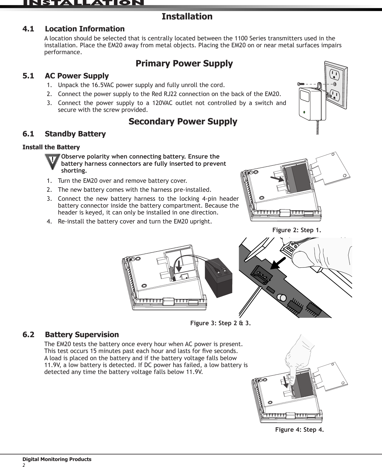
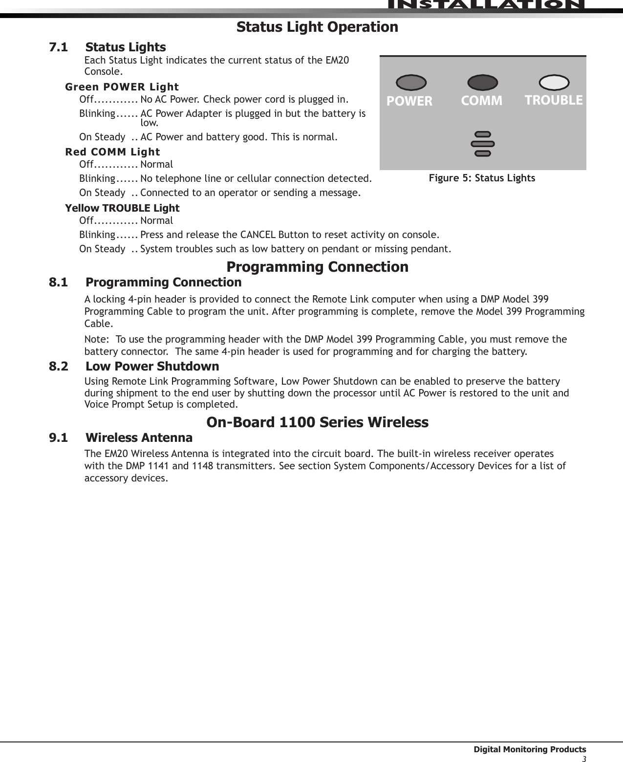
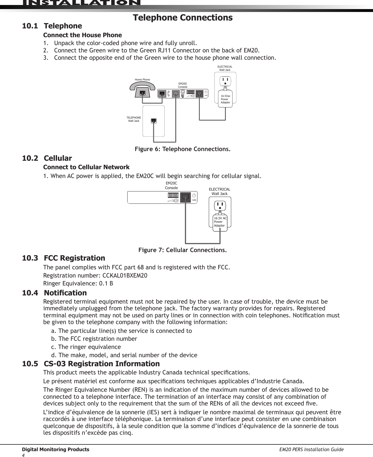
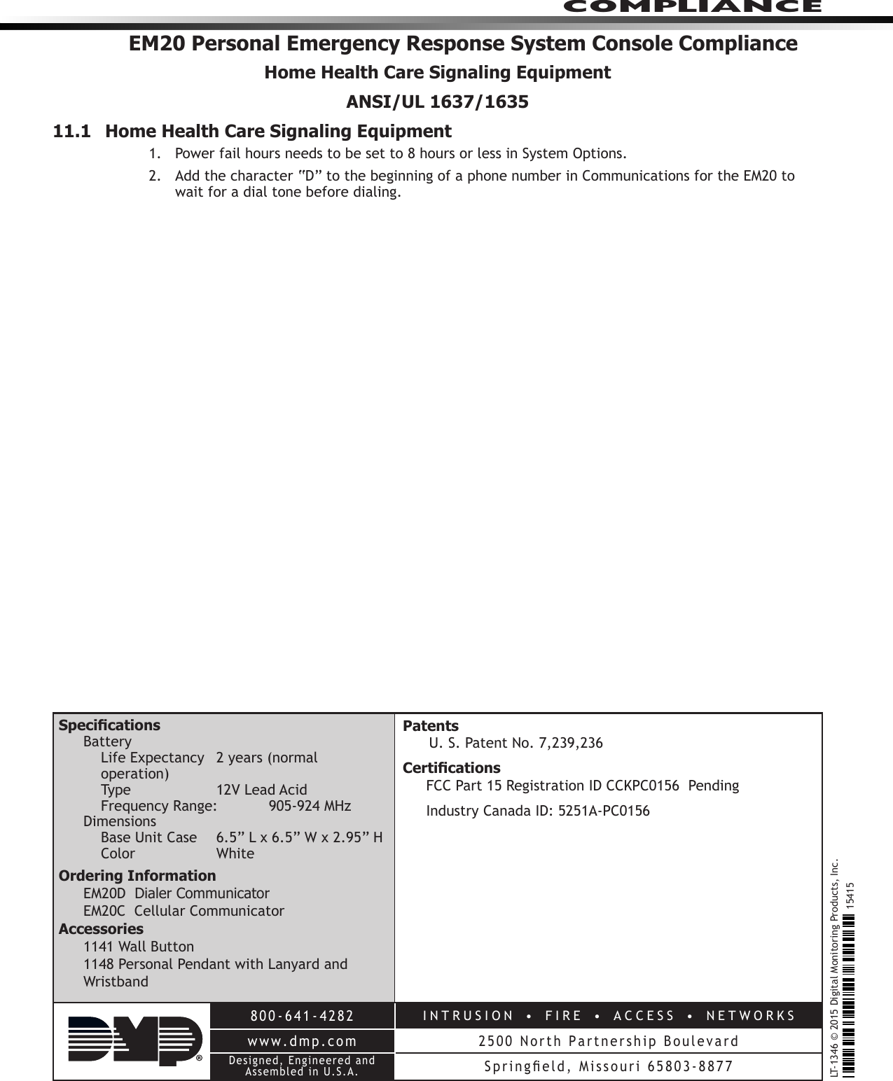
Installation Guide
Installation Guide
Navigation menu
Upload a User Manual
Namespaces
Wiki Guide
HTML
PDF
Info
Views
User Manual
Discussion / Help
Navigation