Digital Ally VULINK1 DIGITAL TRANSMISSION SYSTEM (2400-2483.5 MHz) User Manual DVM 250 250Plus Installation Guide
Digital Ally, Inc. DIGITAL TRANSMISSION SYSTEM (2400-2483.5 MHz) DVM 250 250Plus Installation Guide
UserManual.wiki
>
Digital Ally
>
VULINK1 User Manual
User Manual
Navigation menu
Upload a User Manual
Namespaces
Wiki Guide
HTML
PDF
Info
Views
User Manual
Discussion / Help
Navigation
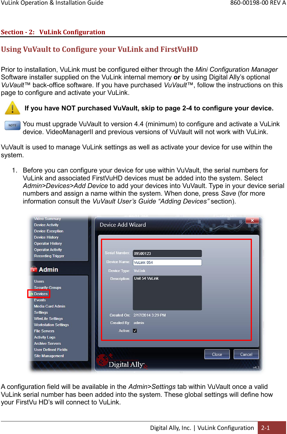
![VuLink Operation & Installation Guide 860-00198-00 REV A Digital Ally, Inc. | VuLink Configuration 2-2 Configuring VuLink VuLink acts as an 802.11n wireless access point which your FirstVu HD’s will use to communicate with your in-car video system. After you have made your selections, press Save. Network SSID The SSID is the wireless network name. This parameter specifies the VuLink SSID that your FirstVu HD’s are authorized to connect to. Password This parameter specifies the password or security phrase required to connect to VuLink. Channel This parameter specifies the wireless channel that your FirstVu HD’s will use to connect to the VuLink. Settings: 1 to 11, Auto [default] Authentication Mode This parameter specifies the security authentication required by VuLink. Settings: WPAPSK, WPA2PSK [default]](https://usermanual.wiki/Digital-Ally/VULINK1/User-Guide-2235565-Page-6.png)
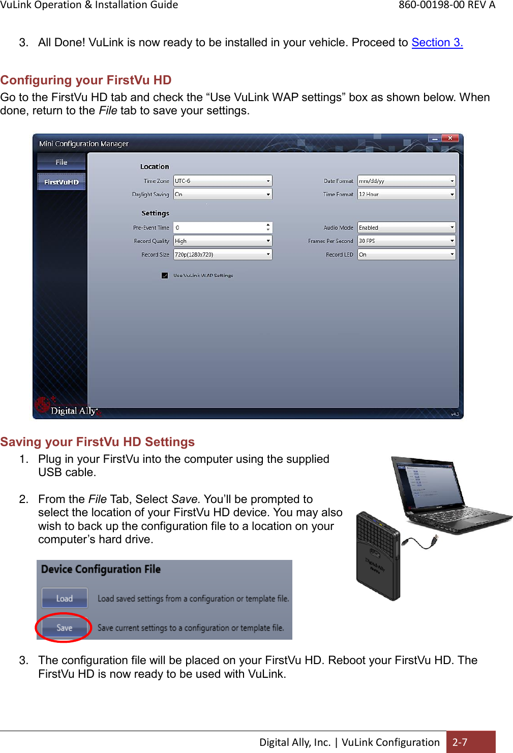
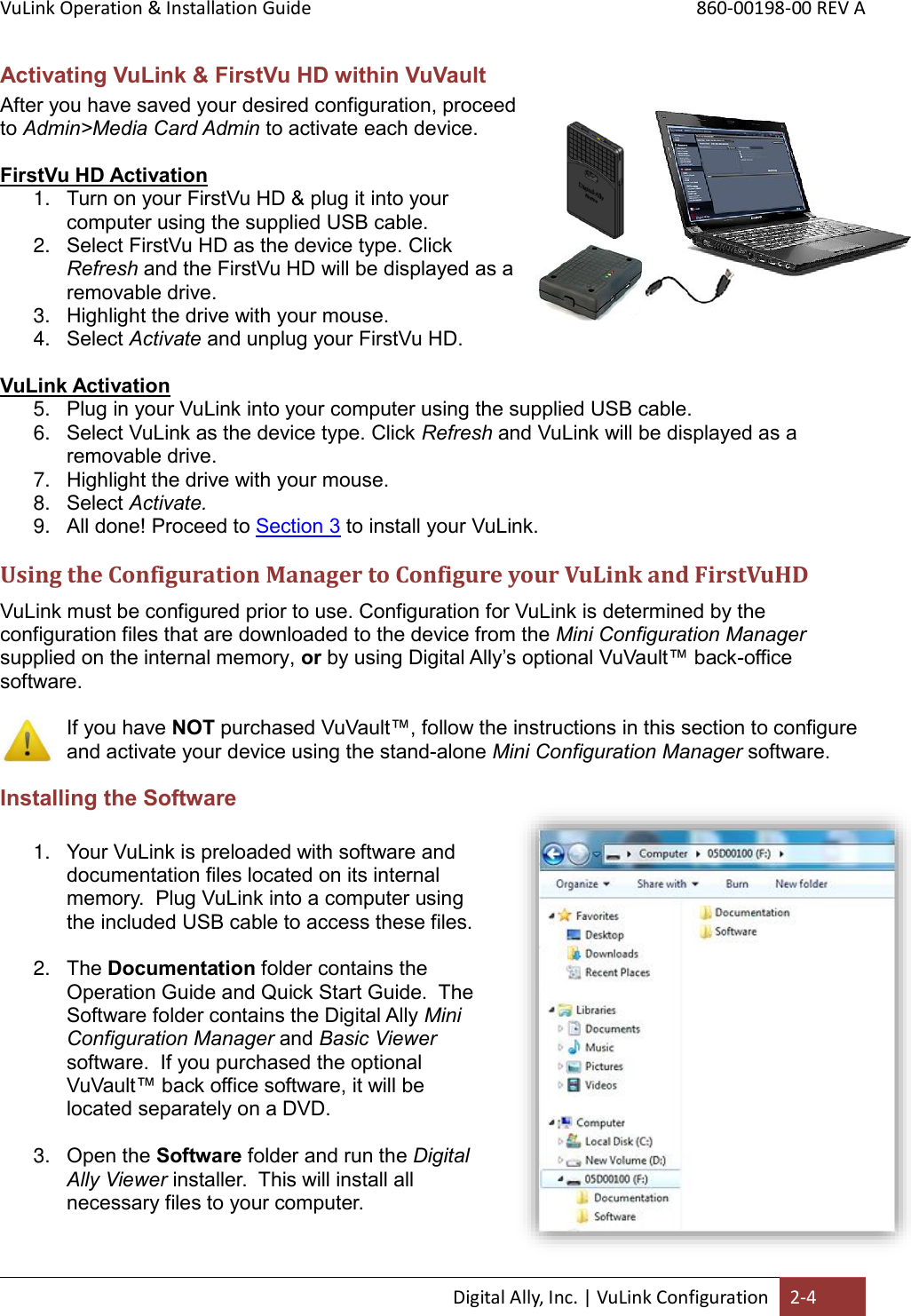
![VuLink Operation & Installation Guide 860-00198-00 REV A Digital Ally, Inc. | VuLink Configuration 2-3 Encryption Type This parameter specifies the wireless encryption protocol required by VuLink. If selecting WPA2PSK as the authentication mode, choose AES as the encryption type. If selecting WPAPSK as the authentication mode, choose TKIP as the encryption type. Settings: TKIP, AES [default] Broadcast SSID Choose whether or not to broadcast the SSID. Broadcasting allows computers with wireless cards to find the network by browsing. Disabling the broadcast of the SSID prevents browsing to find the network. Settings: On, Off [default] Configuring your FirstVu HD Go to the FirstVu HD settings tab and check the “Use VuVault WAP settings” box as shown below. When done, press Save.](https://usermanual.wiki/Digital-Ally/VULINK1/User-Guide-2235565-Page-7.png)
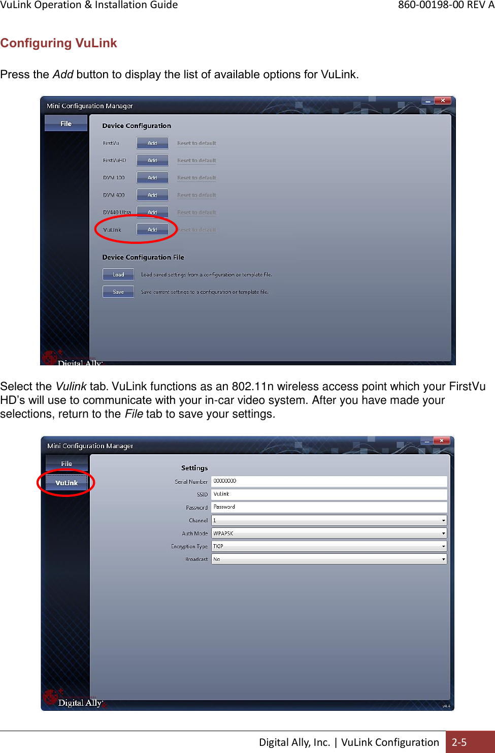
![VuLink Operation & Installation Guide 860-00198-00 REV A Digital Ally, Inc. | VuLink Configuration 2-6 Settings Serial Number This is the serial number printed on your VuLink device. Type in your serial number here. (Example 09500061). SSID The SSID is the wireless network name. This parameter specifies the VuLink SSID that your FirstVu HD’s are authorized to connect to. Password This parameter specifies the password or security phrase required to connect to VuLink. Channel This parameter specifies the wireless channel that your FirstVu HD’s will use to connect to the VuLink. Settings: 1 to 11, 1 [default] Authentication Mode This parameter specifies the security authentication required by VuLink. Settings: WPAPSK, WPA2PSK [default] Encryption Type This parameter specifies the wireless encryption protocol required by VuLink. If selecting WPA2PSK as the authentication mode, choose AES as the encryption type. If selecting WPAPSK as the authentication mode, choose TKIP as the encryption type. Settings: TKIP, AES [default] Broadcast Choose whether or not to broadcast the SSID. Broadcasting allows computers with wireless cards to find the network by browsing. Disabling the broadcast of the SSID prevents browsing to find the network. Settings: On, Off [default] Saving your VuLink Settings 1. Connect VuLink to your computer through the supplied USB cable. Your computer will recognize it as a removable drive and the serial number will be displayed. 2. From the File Tab, Select Save. You’ll be prompted to select the location of your Vulink device. You may also wish to back up the configuration file to a location on your computer’s hard drive. The configuration file named “deviceconfig” will be written to VuLink.](https://usermanual.wiki/Digital-Ally/VULINK1/User-Guide-2235565-Page-10.png)