Datron World Communications G25RMV110 VHF Mobile Radio User Manual G25AMK005a
Datron World Communications Inc VHF Mobile Radio G25AMK005a
UserManual.wiki
>
Datron World Communications
>
G25RMV110 User Manual
>
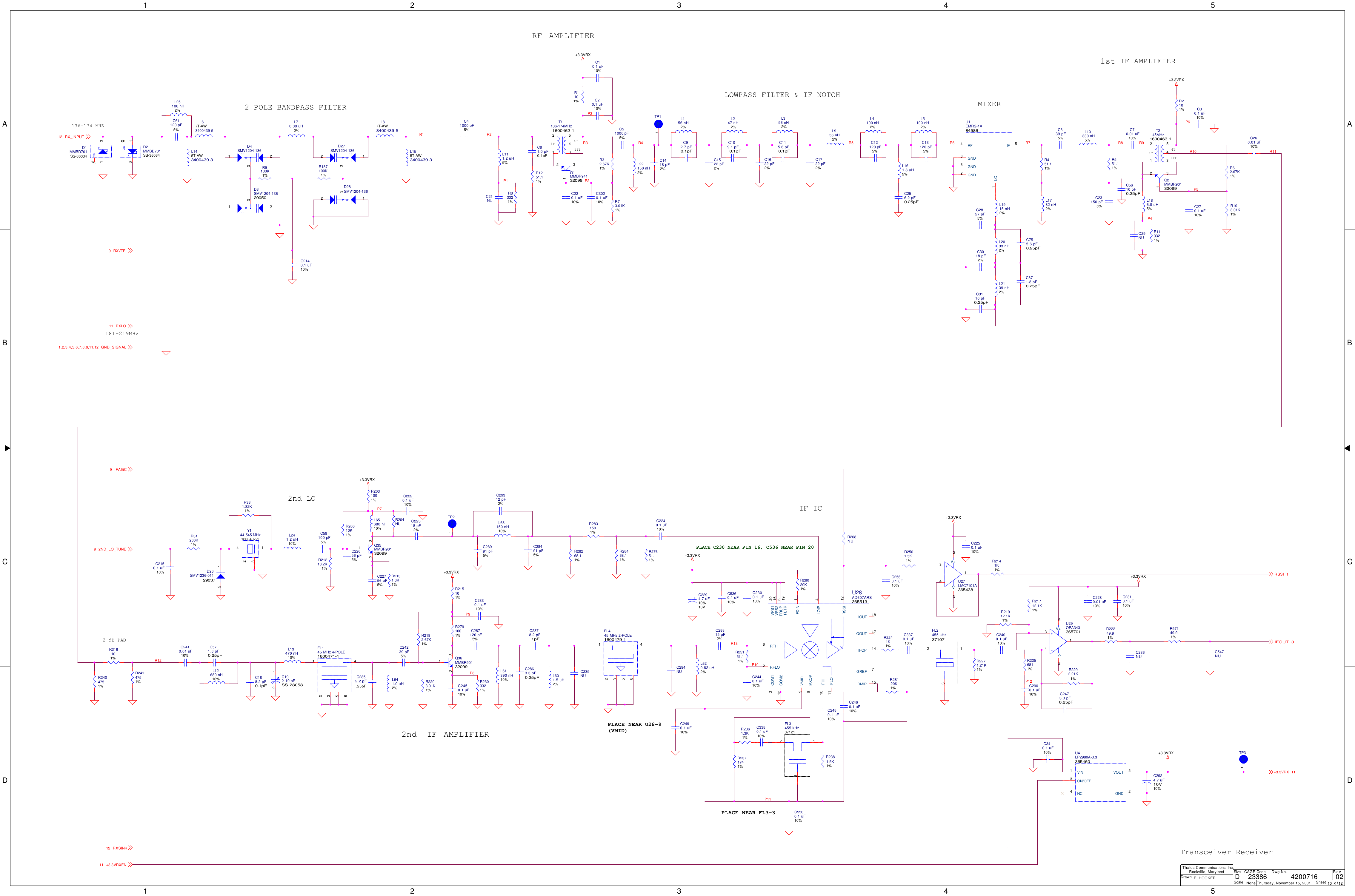
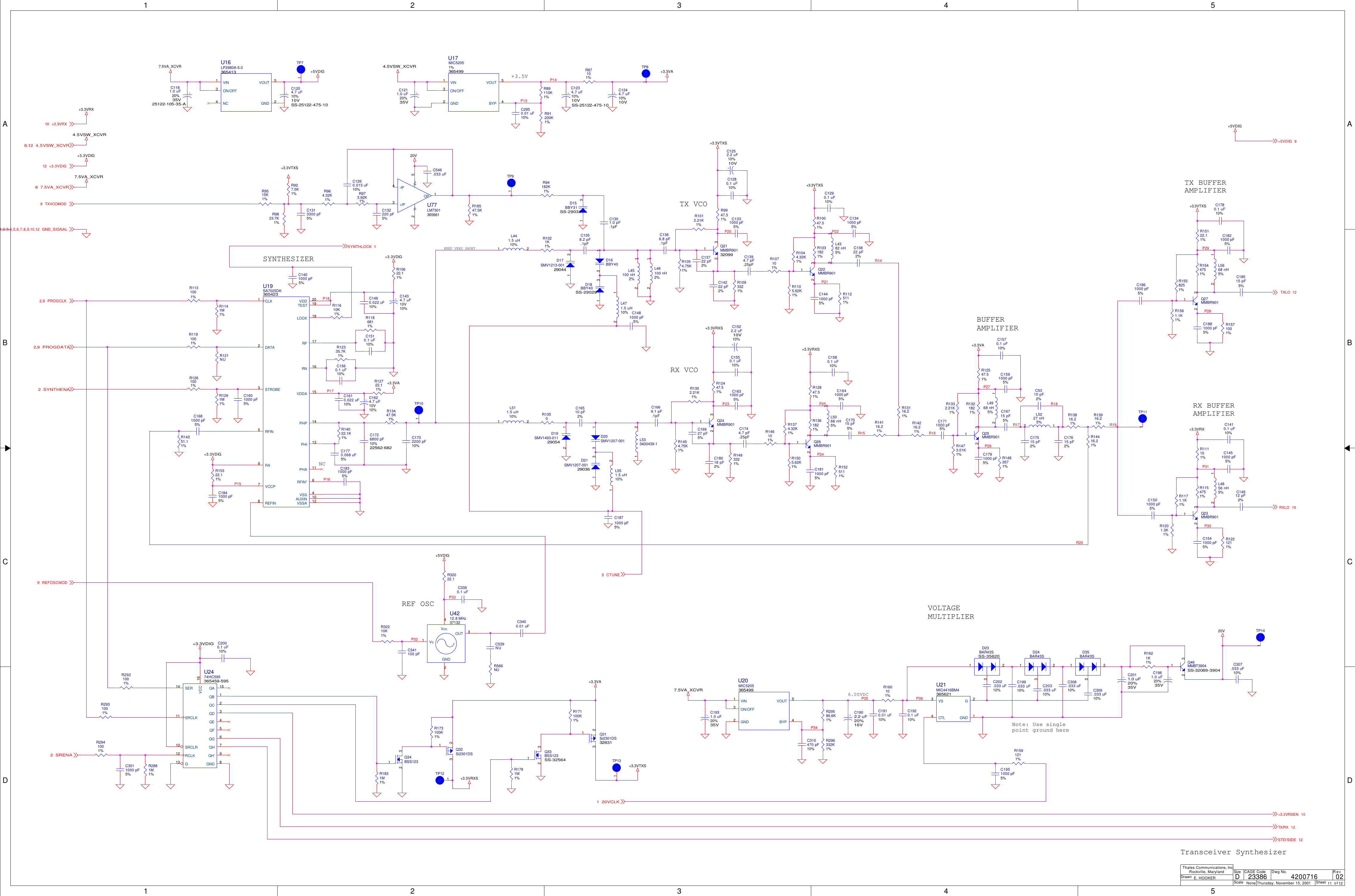
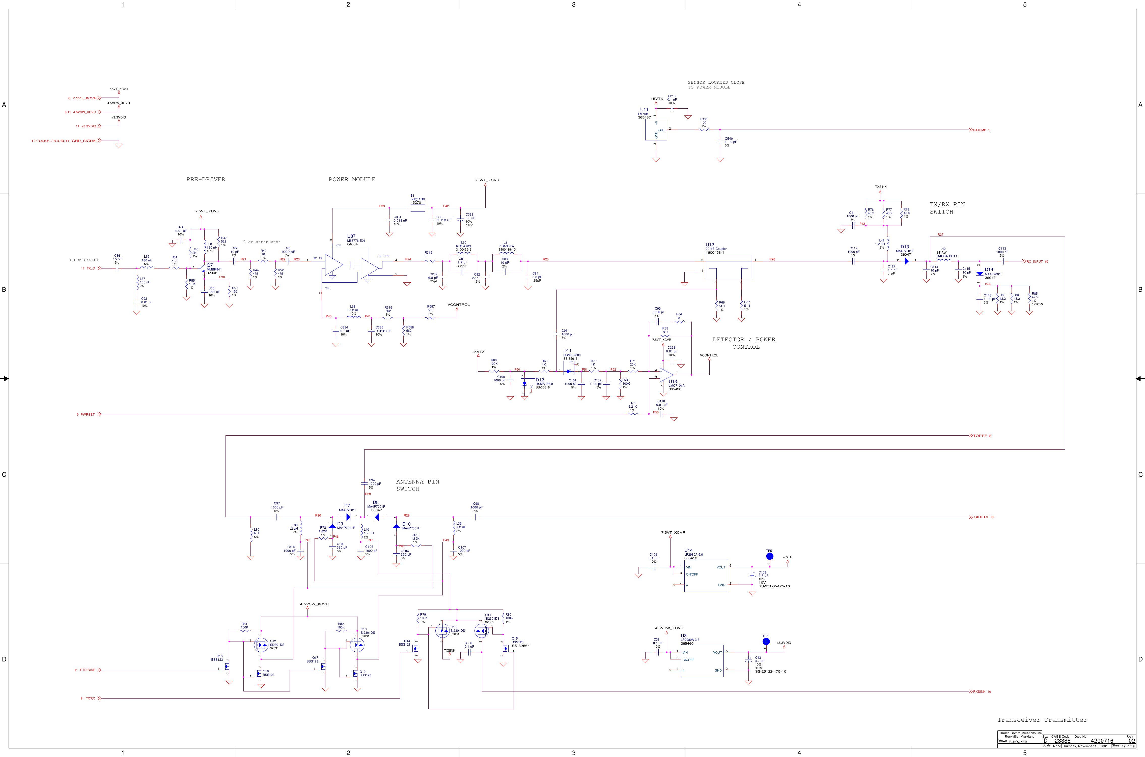
Technical Manual
Contents
1.
Operator Manual
2.
Technical Manual
3.
Revised Page 3 of Manual
Technical Manual
Navigation menu
Upload a User Manual
Namespaces
Wiki Guide
HTML
PDF
Info
Views
User Manual
Discussion / Help
Navigation
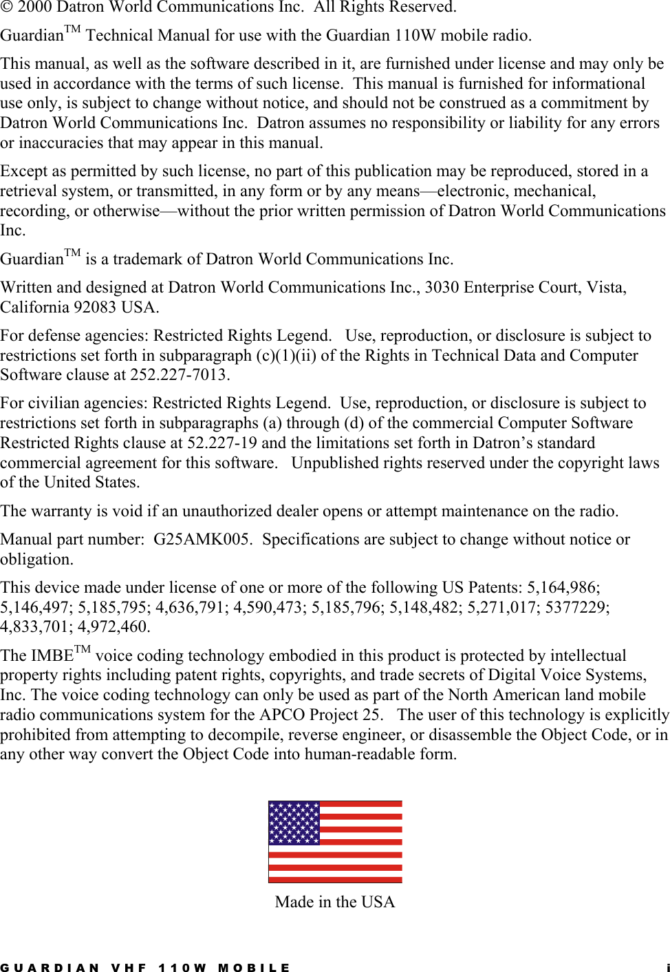

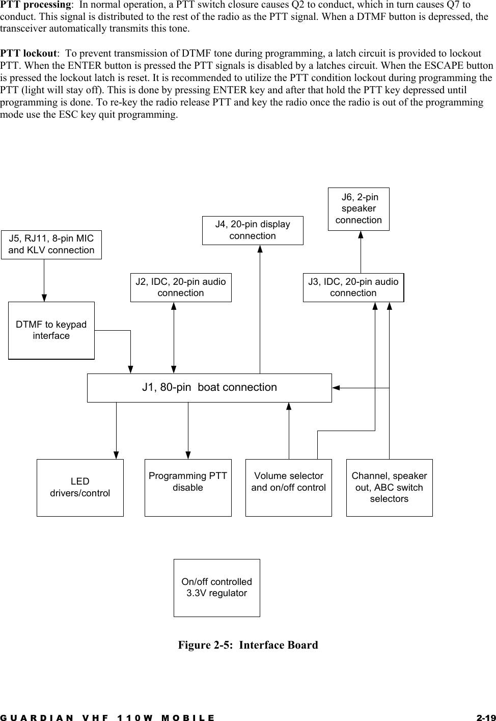
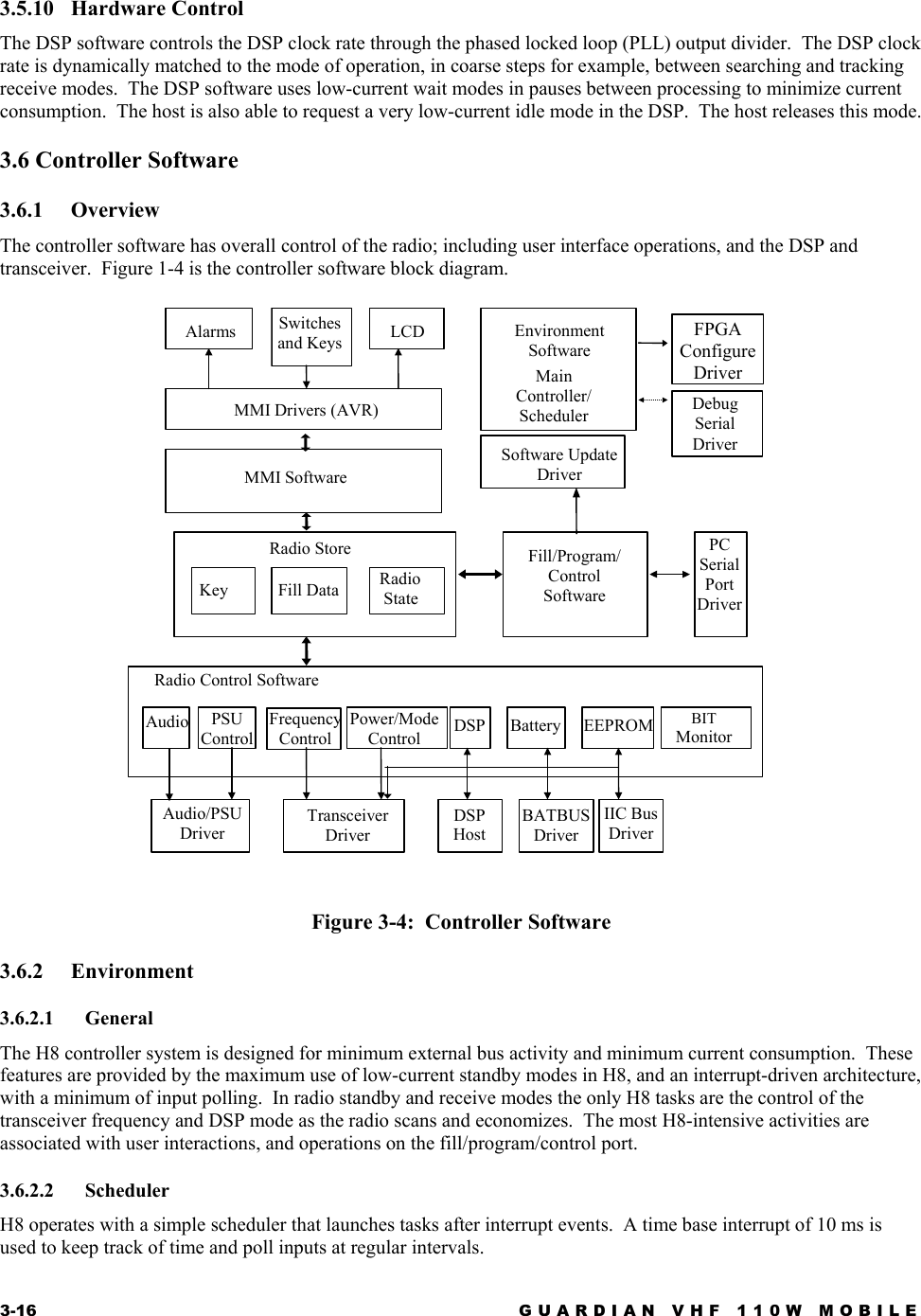


![1122334455A AB BC CD DXTALVCCXTALCLK DVRINCLKCLKDVRVCCRSTVCCFLASHVCCFLASHVPPDVROUTCLKTCXOCTRLTCXOCTRLRAMVCCDB10DB7DB0DB3DB10AB1DB13AB8AB7 DB3AB20DB4AB0/RESDB15AB15AB6 DB2AB18DB1DB0/RESOBATTMONAB14AB18DB4AB2DB1AB19DB8AB16AB17DB15AB5DB7AB2AB1AB10AB3AB9AB1AB9DB15AB14AB15DB14AB10DB8AB11AB16AB12AB0DB6AB17DB12AB13AB2AB12AB13AB5AB19AB11DB11AB12AB3DB8DB14DB9AB14AB11AB8AB20DB13AB4/RES DB2AB15AB7AB6DB12AB9AB6DB5 DB10AB8/RESOAB16DB13AB10AB4DB11DB9DB14AB7AB3DB5AB5DB12DB11DB9AB4DB6AB13MPUCLKMPUCLK3V3LOGIC3V3LOGIC3V3LOGIC3V3LOGIC3V3LOGIC3V3LOGIC3V3LOGIC3V3LOGIC3V3LOGIC3V3CONTH8VCCH8VCC3V3LOGICH8VCC3V3LOGIC3V3LOGIC3V3LOGIC3V3LOGIC3V3LOGIC3V3LOGIC/STBY1,3,5SYNTHOOL1DRXD1/WP1DTXD1/DSPO_CS3SYNTHENA11PROGDATA9,11/BREQ 3/BACK 3DSPWD3/RES 5DB[0..15] 3/RD 3/WR 1,3,5/RAM_CS 3/FLASH_CS 3LBI 6RSSIMON 1,38DACENA9WRUMON 1KEYLOAD5AB[0..20] 3,5DATIN_H8 5/MINT 7CONFDONE5ALM 4/LBOUT3,6SOCLK 5TXDO 5232RTS_H8 5/EXTPTT 5,6/HINT 3/XRST 1,3,7/FPGA_CS 5DATOUT_H8 5PATMON 1RXDO 5GND_SIGNAL1,3,4,5,6,7,8,9,10,11,12SRENA11VPPCTRL3BATTBUS1/DINT3PROGCLK9,11/PWROFF6FPGACLK 5DSPCLK 3ScaleRevSheet ofSizeCAGE Code Dwg No.None23386DrawnThales Communications, Inc.Rockville, MarylandThursday, November 15, 2001 2 12024200716E. HOOKERDALARM INPUT?Control MPUU64IS62LV12816LL-70BI365766A0A3A1A4A2A5A3B3A4B4A5C3A6C4A7D4A8H2A9H3A10H4A11H5A12G3A13G4A14F3A15F4A16E4IO0 B6IO1 C5IO2 C6IO3 D5IO4 E5IO5 F5IO6 F6IO7 G6GNDD1UB#B2CE#B5OE#A2WE#G5VCC D6LB#A1NC A6IO8 B1IO9 C1IO10 C2IO11 D2IO12 E2IO13 F2IO14 F1IO15 G1NC D3VCC E1NC E3GNDE6NC G2NC H1NC H6R514150K1%R505101%R50610K1%C4820.1 uF10%C4850.01 uF10%PORT APORT BPORT 9PORT 8PORT 7U63HD6433044SS00XI365582VCC 68517416315214113012491390MD275MD174MD073EXTAL66XTAL67^61STBY62RES63VPP* /RESO10NMI6409319429539649759869971000213243546576879289188087785684583482381280179078AVSS86VSS11VSS22VSS44VSS57VSS65VSS92018119220321423524625726053154255356058159260369470571672VCC 35VCC 1AVCC 76VREF 77734633532431330128229027752651550449348247146045743642541440339238137036U6812.288 MHzO.P 3VCC4VCONT1GND2Q662N7002132U60MAX825TEUKRESET 3MR4RESET 1GND2VCC5R5371001%C507100 pF5%R511150K1%U62RC28F160C3BA90365764A1A1A2B1A3C1A4D1A5D2A6A2A7C2A8D7A9D8A10A7A11B7A12C7A13C8A14B8A15A8A16G8A17B2A18A3DQ0 F2DQ1 E2DQ2 G3DQ3 E4DQ4 G4DQ5 F5DQ6 E6DQ7 H6DQ8 E1DQ9 E3DQ10 F3DQ11 F4DQ12 E5DQ13 G5DQ14 F6DQ15 G6GNDA6GNDG7OE#H2 CE#F1 WP#C3 RP#B4 WE#C4VPP A4VCCQ H3A19B3A0G1VCCQ H7VSSQH5 VSSQG2VCC H4VCC A5R5364.75K1%R517150K1%R518NUC4870.01 uF10%C4840.1 uF10%C490100 pF5%C4970.1 uF10%Q672N7002132C4861000 pF5%L77BEADC4830.01 uF10%+C4962.2 uF10%10VR513221K1%R516182K1%R507101%R56782.51%R51582.51%R56882.51%R51210K1%C48812 pF5%R56310K1%R57910K1%R56410K1%R5341001%+C4892.2 uF10%10VR58010K1%R5301001%C5020.01 uF10%R32110K1%R5351001%R32310K1%C504100 pF5%L761.2 uH5%R5334.75K1%C5030.01 uF10%R57210K1%C5060.01 uF10%R5291001%R528100 1%R531100K1%C5050.01 uF10%C5380.1 uF10%R522100K1%R52310K1% R525100K1%C4910.1 uF10%U71NC7SZ14365647SOT23/5PNC1A2GND3Y4VCC 5C5000.1 uF10%C4920.1 uF10%R521100 1%C4930.1 uF10%L78BEADU69NC7SZ126SC70-536577312345+C4992.2 uF10%10VC4980.01 uF10%C4940.1 uF10%Q65BSS84TA132C5370.1 uF10%R524100K1%R510101%C5010.01 uF10%L75BEADU70NC7SZ126SC70-536577312345R5261001%R527100K1%C495NU](https://usermanual.wiki/Datron-World-Communications/G25RMV110.Technical-Manual/User-Guide-246402-Page-75.png)
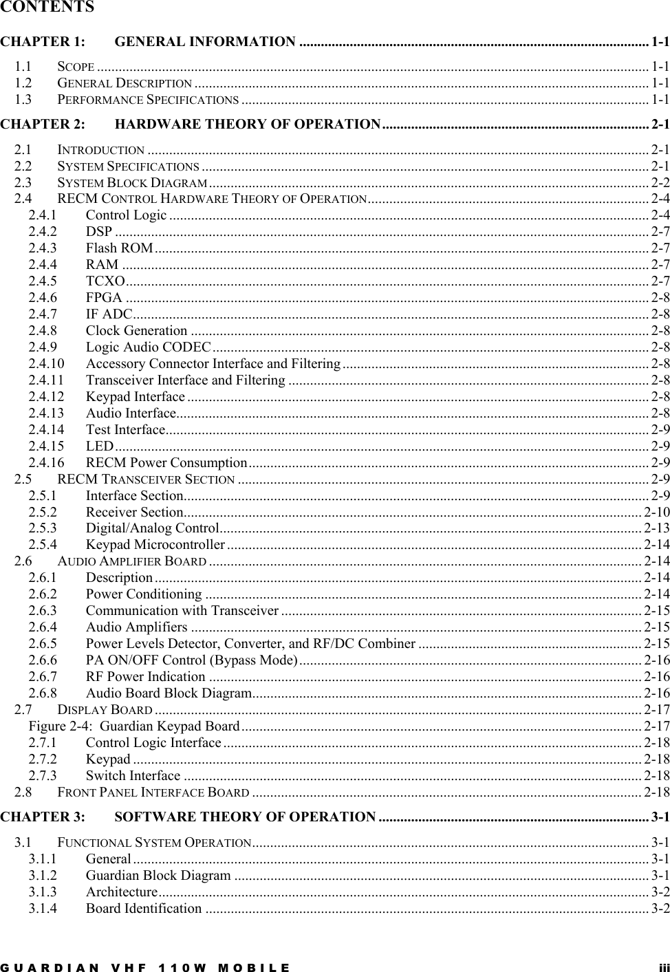
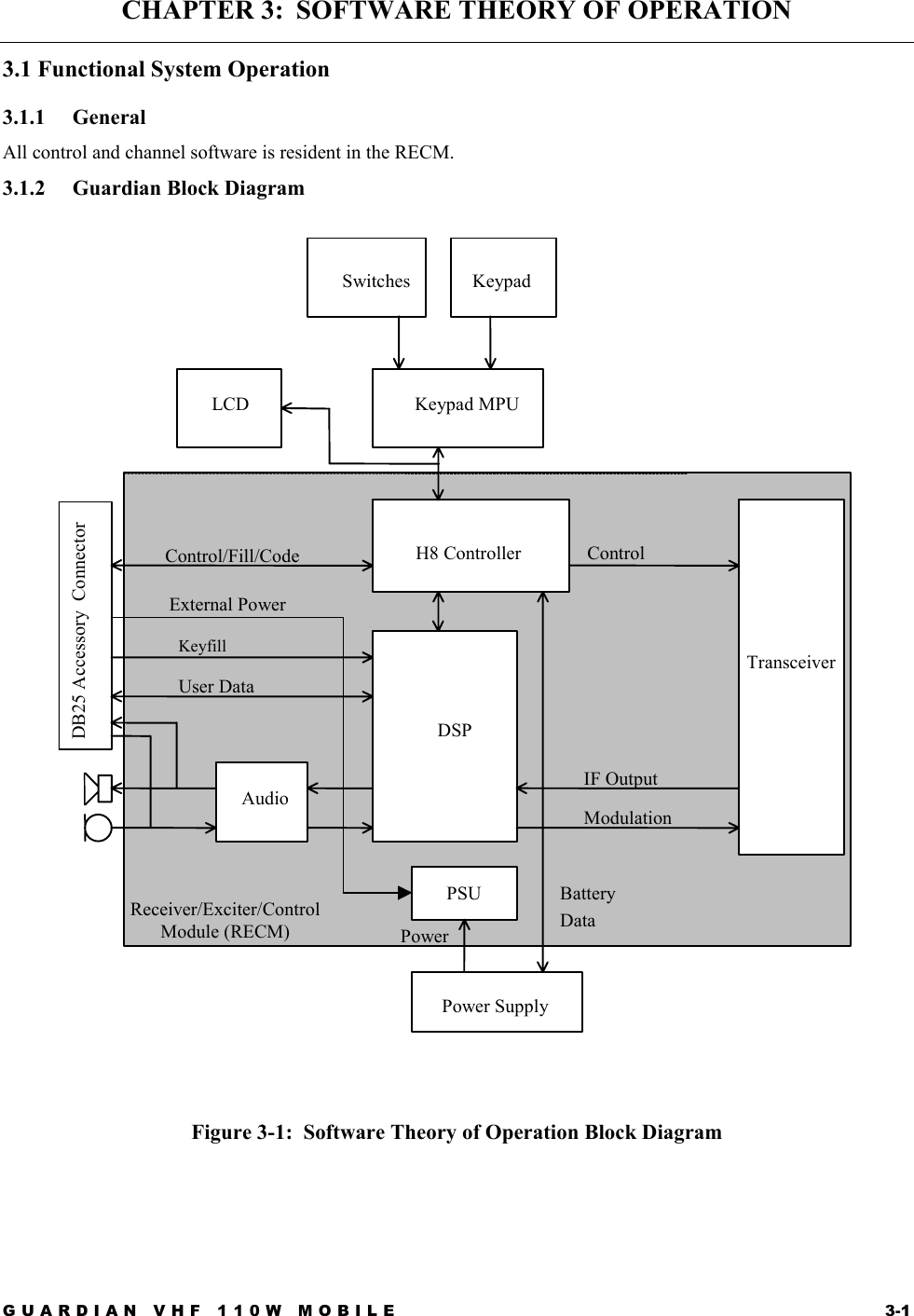
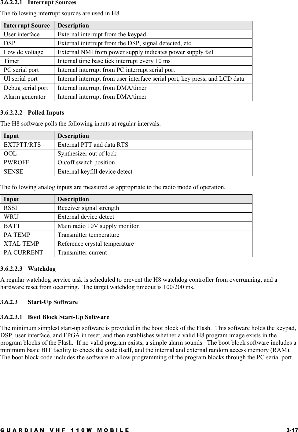
![1122334455A AB BC CD D455IFCOUTADCDINADCDOUTAB10AB3DB13AB18DB15AB2AB0 DB9DB6AB17AB16DB13AB11AB9AB6AB2DB12DB0DB15DB14AB1AB19DB8DB14DB11DB5AB8DB9AB7AB5AB4DB10DB8AB0DB12DB10DB3AB12AB1DB11DB7DB4DB2AB15AB13DB1AB14ADCVCCADCREFVCCADCDOUTADCDINDSPVCC3V3LOGIC3V3ANALOG3V3ANALOG3V3LOGIC3V3LOGICDACADCCLK1,5IFOUT10/RD2/WR1,2,5/BREQ2/BACK2/STBY1,2,5DSPCLK2/LBOUT2,6DB[0..15]2AB[0..20]2,5/FLASH_CS2/RAM_CS2RSSIMON1,212DACDATA 9/DSPO_CS 2CODECFSK 4232RXD_DSP 5/RESET_JTAG1,2,7/IRQD 5TDI 1/HINT 2232TXD_DSP 5CODECDOUT 4CODECCLK 4DACADCCLK 1,5232CTS/DIGSQ_DSP 5/DINT 2VPPCTRL 2TCK 1,5/DE 1CODECDIN 4DSPWD 2/CODECEARMUTE 4232RTS/EORS_DSP 5232DTR/SYNC_DSP 5/TRST 112DACENA 9/WR 1,2,5TDODSP 5/CODECMICMUTE 4/XRST1,2,7/RD 2232CLK_DSP 5TMSDSP 1,5GND_SIGNAL1,2,4,5,6,7,8,9,10,11,12ScaleRevSheet ofSizeCAGE Code Dwg No.None23386DrawnThales Communications, Inc.Rockville, MarylandThursday, November 15, 2001 3 12024200716E. HOOKERDDECOUPLING CAPS MUST BE CLOSE TO DSP VCC PINS1.536 MHz2.048 MHzControl DSPTEST PADR5411001%C523.033 uF10R54247.51%C5430.047 uF10%R5441001%C5340.01 uF10%R53910K1%R5451001%R549100K1%R555100K1%R5481001%C5290.1 uF10%R5511001%R5531001%R5561001%C5210.01 uF10%C5200.1 uF10%C5190.01 uF10%C5170.01 uF10%C5180.1 uF10%U74MAX1246365695QSOP16/025/210CH02CH13CH24CH35COM6SHDN7VREF 8REFADJ9DIN14SCLK16Vdd 1AGND10DGND11DOUT 12SSTRB 13CS 15C5160.1 uF10%C5150.01 uF10%C54112 pF5%R547101%C5140.1 uF10%+C5284.7 uF10%10VC5130.01 uF10%C5120.1 uF10%C5110.01 uF10%C5100.1 uF10%C5090.01 uF10%+C5222.2 uF10%10VC5080.1 uF10%E4PAD21L79BEADR54010K1%R5461001%R55210K1%R569NU R550NUC525100 pF5%C532NUC526100 pF5%C527100 pF5%C531100 pF5%C535100 pF5%CLOCKPLLPORT ATIMERPORT EPORT DPORT CPORT BU65XC56309GC100A365770GNDD4GNDD5GNDD6GNDD7GNDD8GNDD9GNDD10GNDD11EXTALM8XTALP8CLKOUTM9PCAPP5GNDE4GNDE5GNDE6GNDE7GNDE8GNDE9GNDE10GNDE11GNDF4VCCQL N9VCCQH M7VCCP M6VCCH M4VCCA L12VCCA K12VCCS K1VCCA H12VCCQL H2VCCQH H1VCCQL G13VCCQH F12VCCS E2VCCD D14VCCD C11VCCD C9VCCQL C7VCCD A7PINIT/NMID1A0N14A1M13A2M14A3L13A4L14A5K13A6K14A7J13A8J12A9J14A10H13A11H14A12G14A13G12A14F13A15F14A16E13A17E12D0E14D1D12D2D13D3C13D4C14D5B13D6C12D7A13D8B12D9A12D10B11D11A11D12C10D13B10D14A10D15B9D16A9D17B8D18C8D19A8D20B7D21B6D22C6D23A6AAON13AA1P12AA2P7AA3N7RDM12WRM11TAP10BRN11BGP13BBP11CASN8BCLKN10BCLKM10GNDF5MODAIRQA C4MODBIRQB A5MODCIRQC C5MODDIRQD B5RESET N5H0 M5H1 P4H2 N4H3 P3H4 N3H5 P2H6 N1H7 N2HA0 M3HA1 M1HA2 M2HCS/HCS L1HRW J2HDS/HDS J3HREQ/HREQ K2HACK/HACK J1SC00 F3SC01 D2SC02 C1SCK0 H3SRD0 E3STD0 E1SC10 F2SC11 A2SC12 B2SCK1 G1SRD1 B1STD1 C2RXD F1TXD G3SCLK G2TI00 L3TI01 L2TI02 K3TCK C3TDI B3TDO A4TMS A3TRST B4DE D3NC A1NC A14GNDG4NC B14GNDF6GNDF7GNDF8GNDF9GNDF10GNDF11GNDG5GNDG6GNDG7GNDG8GNDG9GNDG10GNDG11GNDH4GNDH5GNDH6GNDH7GNDH8GNDH9GNDH10GNDH11GNDJ4GNDJ5GNDJ6GNDJ7GNDJ8GNDJ9GNDJ10GNDJ11GND K4GND K5GND K6GND K7GND K8GND K9GND K10GND K11GND L4GND L5GND L6GND L7GND L8GND L9GND L10GND L11GNDP N6VCCC N12NC P1GNDP1 P6VCCC P9NC P14+-U73NUSOT23/3P123R54310K1%R570NUR53833.2K1%R55410K1%C524100 pF5%](https://usermanual.wiki/Datron-World-Communications/G25RMV110.Technical-Manual/User-Guide-246402-Page-76.png)
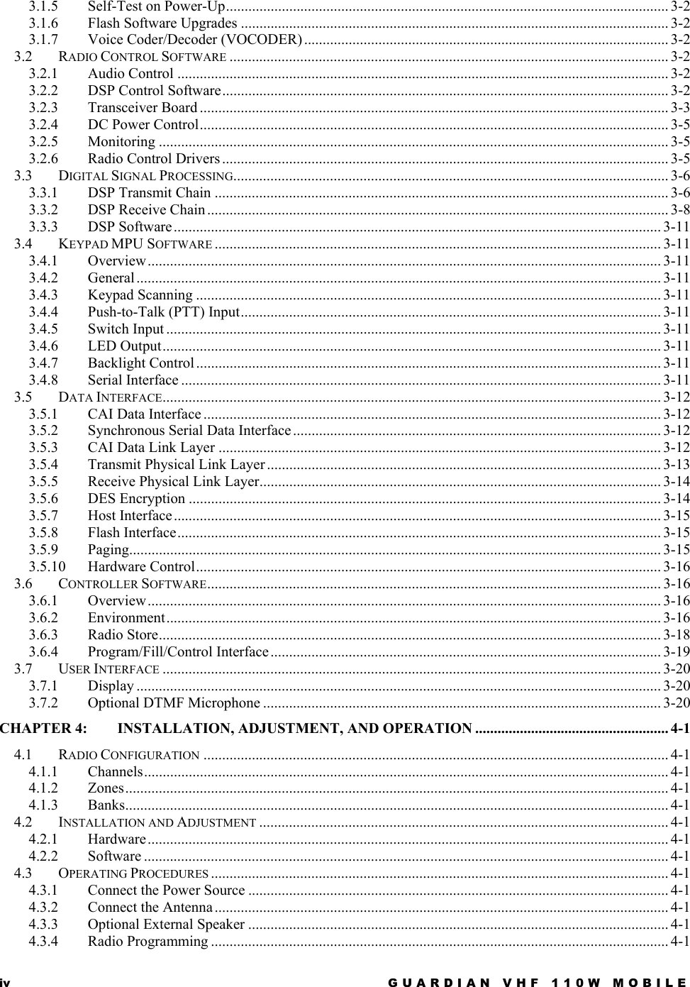
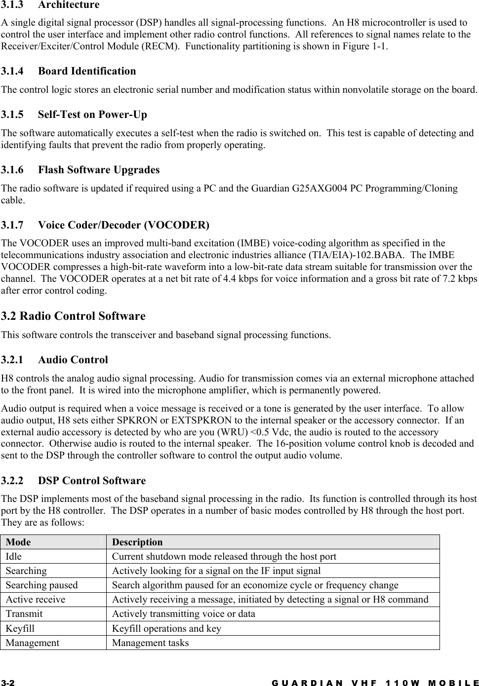
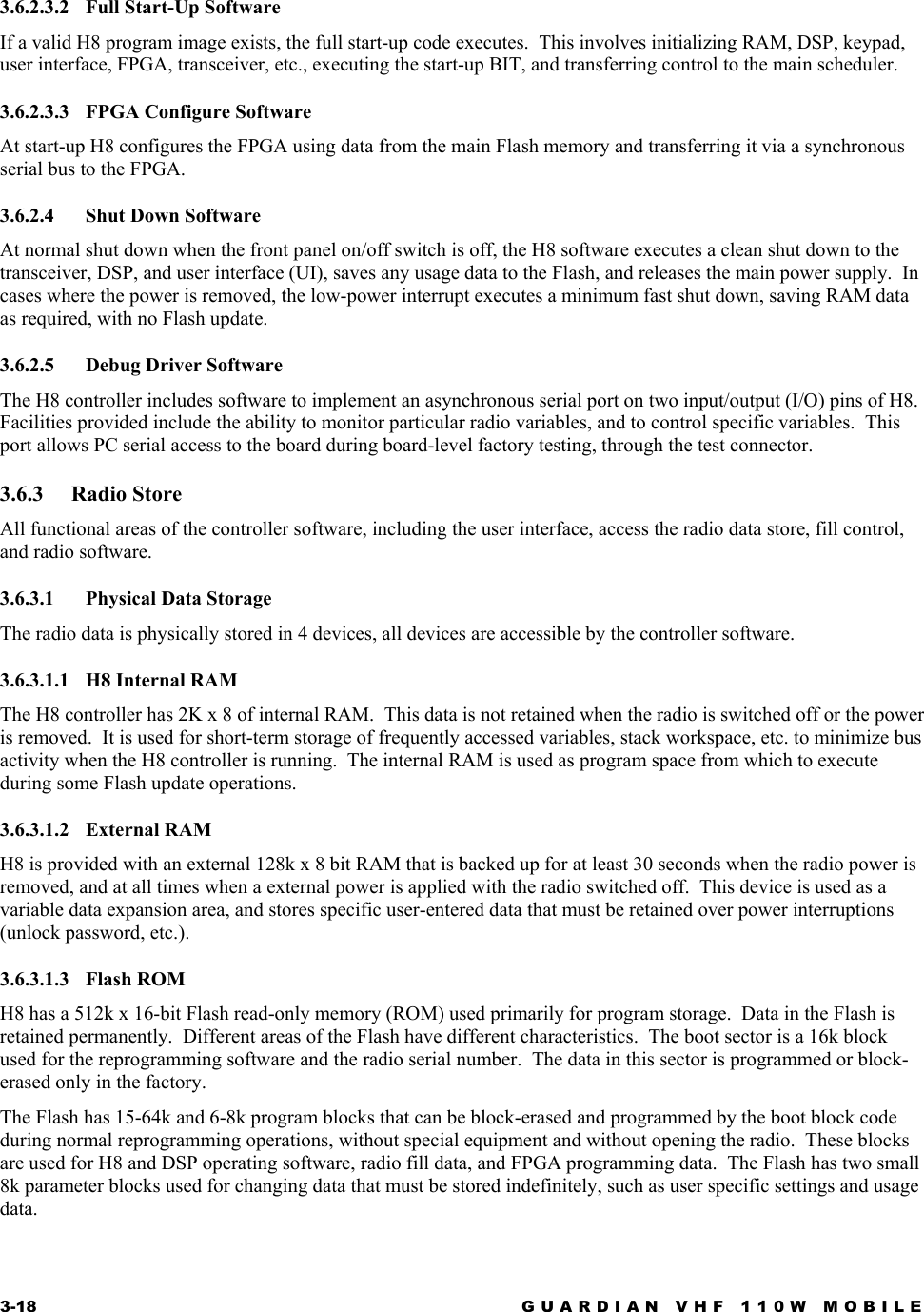
![1122334455A AB BC CD DFPGAVCCKVLSELAVR_CLK232DTRIN232TXDIN232RTSINKEYOUTKEYINKEYIDDAC_ADC_CLK232CTSOUT232RXDOUT232CLKOUT232DTRIN232RTSIN232CLKOUT232CTSOUT232VCCKEYIDKVLSELKEYINKEYOUTAB16AB17AB18AB19/WE/WE AVR_CLKDAC_ADC_CLKLEDGREENLEDGREENPSU_CLKPSU_CLK/232SHDN/232SHDNLEDREDLEDRED232RXDOUT232TXDINAB203V3LOGIC3V3LOGIC3V3LOGIC5VLOGIC5VLOGIC5VLOGIC 5VLOGIC 5VLOGIC3V3LOGIC 3V3LOGIC3V3LOGIC 3V3LOGIC5VLOGIC5VLOGIC 3V3LOGIC5VLOGICRXDO 2232RTS/EORS_DSP 3/IRQD 3SPKRON 4232RTS_H8 2232DTR/SYNC_DSP 3DACADCCLK 1,3232DTR_SC 1232TXD_SC 1232RTS_SC 1PCTXD_SC 1232CTS_SC 1232CLK_SC 1232RXD_SC 1PCRXD_SC 1DATOUT_H82DATIN_H82232CLK_DSP 3LEDREDN 1LEDGREENN 1EXTMIC/WE1EXTPTT/KID1EXTSPKR+/KLD1,4EXTMIC 4/EXTPTT 2,6KEYLOAD 2EXTMICB/KEY1MULTCLOCK 1MRXD 7AVRCLK 7232CTS/DIGSQ_DSP 3GND_SIGNAL1,2,3,4,6,7,8,9,10,11,12/RES2SOCLK2TXDO2CONFDONE2FPGACLK2232RXD_DSP 3EXTSPKRON4AB[0..20]2,3/WR1,2,3/FPGA_CS2/LCD_CS1MCLK1,7MTXD1,7SQL_SC1/KPD_CS7PWRHOLD6CTX1/BATTOFF1LCDA01TCK1,3TDODSP3TMSFPGA1TMSDSP1,3TDO1PSUCLK6/STBY1,2,3232TXD_DSP3ScaleRevSheet ofSizeCAGE Code Dwg No.None23386DrawnThales Communications, Inc.Rockville, MarylandThursday, November 15, 2001 5 12024200716E. HOOKERDControl FPGAR4491K1%C4620.1 uF10%R4471K1%U54MAX213EEAIV+ 13EN24GND10T4I21T2I6R4O22R1O8R2O5T1I7R3O26C1+12T3I20R5O19C2-16 C2+15 C1-14V- 17T10 2T20 3T30 1T40 28R1I 9R2I 4R3I 27R4I 23R5I 18SHDN 25VCC 11R466NUD52CMPSH-3A132R451100K1%R469NUC454100 pF5%Q602N7002132R471101%D53CMDSH2-32 1R468101%R46410K1%L73BEADC4570.1 uF10%Q622N7002 132R4804.75K1%D54CMDSH2-32 1C461100 pF5%R56510K1%D55CMDSH2-32 1D60CMDSH2-321R47510K1%D56CMDSH2-32 1R477100K1%D57CMDSH2-32 1R47610K1%R47810K1%R48110K1%R482150K1%D65CMDSH2-321R46310K1%R46210K1%C456100 pF5%R46110K1%D66BAR43S1 23R460100K1%D62BAR43S1 23D63BAR43S1 23D64BAR43S1 23D59CMDSH2-321C54212 pF5%R44810K1%R467100K1%U55MAX4053NCC 12NOC 13NCB 2NOB 1NCA 5NOA 3INH6ADDC11ADDB10ADDA9COMC14COMB15COMA4V+ 16GND8V-7R446101%R4721K1%+C45515 uF10%10VC4480.1 uF10%Q612N7002132R45922.1K1%D61CMDSH2-321R45247.51%C4490.1 uF10%+C4472.2 uF10%10VC4500.1 uF10%R47010K1%C4510.1 uF10%C4600.1 uF10%R473100K1%R46510K1%C4520.1 uF10%R455150K1%R457101%R479100K1%U53EPF6016AFI100-3365765nCEC2INIT_DONEE10MSELH2nSTATUSG5nCONFIGK5DCLKD6CONFIG_DONEC9nCEOK9nWSC7nRSA7nCSA9CSC8RDYnBUSYD10CLKUSRC10DATAA6TDID2TCKG3 TMSG2 TDOK10INE1INE2INF9INF10DEV_CLRnB5DEV_OEB6GND D4VCC D7VCC E4VCC E5VCC F6VCC F7VCC G4GND E6GND E7GND F4GND G7GND F5I/OA1I/OA2I/OA3I/OA4I/OA5I/OA8I/OA10I/OB1I/OB2I/OB3I/OB4I/OB7I/OB8I/OB9I/OB10I/OC1I/OC3I/OC4I/OC5I/OC6I/OD1I/OD3I/OD5I/OD8I/OD9I/O E3I/O E8I/O E9I/O F1I/O F2I/O F3I/O F8I/O G1I/O G6I/O G8I/O G9I/O G10I/O H1I/O H3I/O H4I/O H5I/O H6I/O H7I/O H8I/O H9I/O H10I/O J1I/O J2I/O J3I/O J4I/O J5I/O J6I/O J7I/O J8I/O J9I/O J10I/O K1I/O K2I/O K3I/O K4I/O K6I/O K7I/O K8C4530.1 uF10%R456150K1%C4580.1 uF10%R4741001%D58CMDSH2-321Q592N7002132C4590.1 uF10%R45356.21%R4581001%R45456.21%R4501K1%](https://usermanual.wiki/Datron-World-Communications/G25RMV110.Technical-Manual/User-Guide-246402-Page-78.png)