Cypress Semiconductor CY8CKIT-142 CY8CKIT-142 PSoC 4 BLE Module User Manual Manual part 2
Cypress Semiconductor CY8CKIT-142 PSoC 4 BLE Module Manual part 2
UserManual.wiki
>
Cypress Semiconductor
>
CY8CKIT-142 User Manual
>
Manual part 2
Contents
1.
Manual part 1
2.
Manual part 2
Manual part 2
Navigation menu
Upload a User Manual
Namespaces
Wiki Guide
HTML
PDF
Info
Views
User Manual
Discussion / Help
Navigation
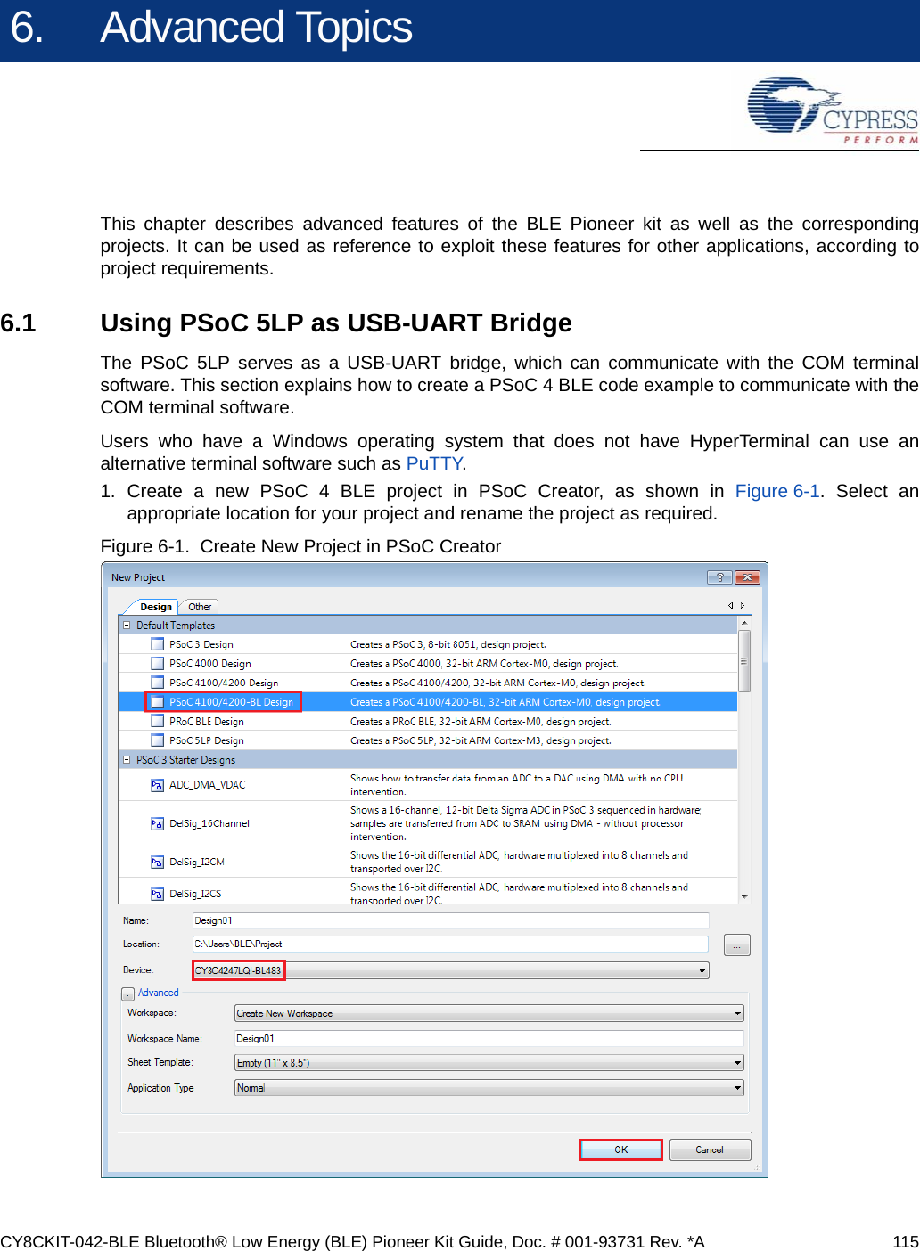
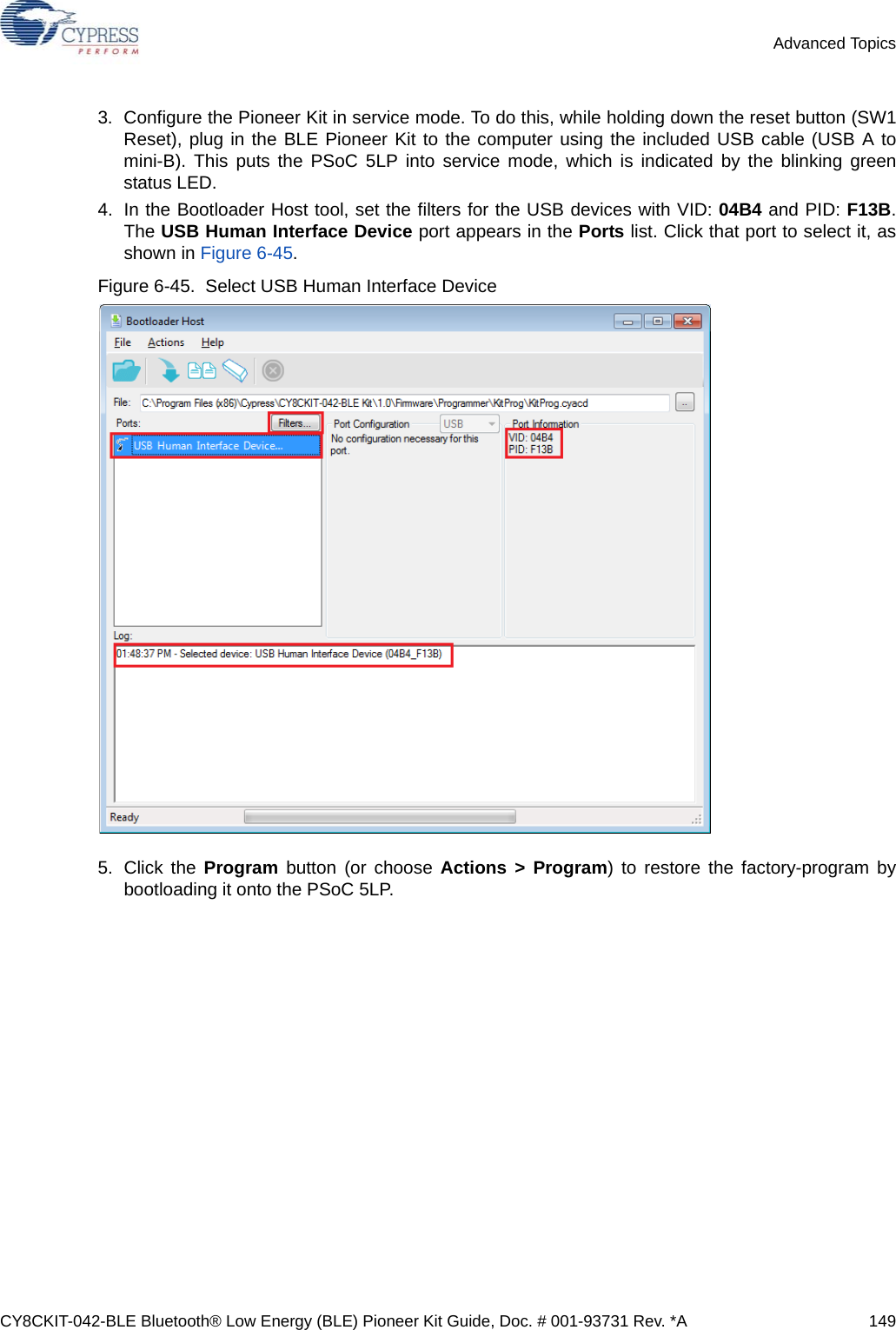
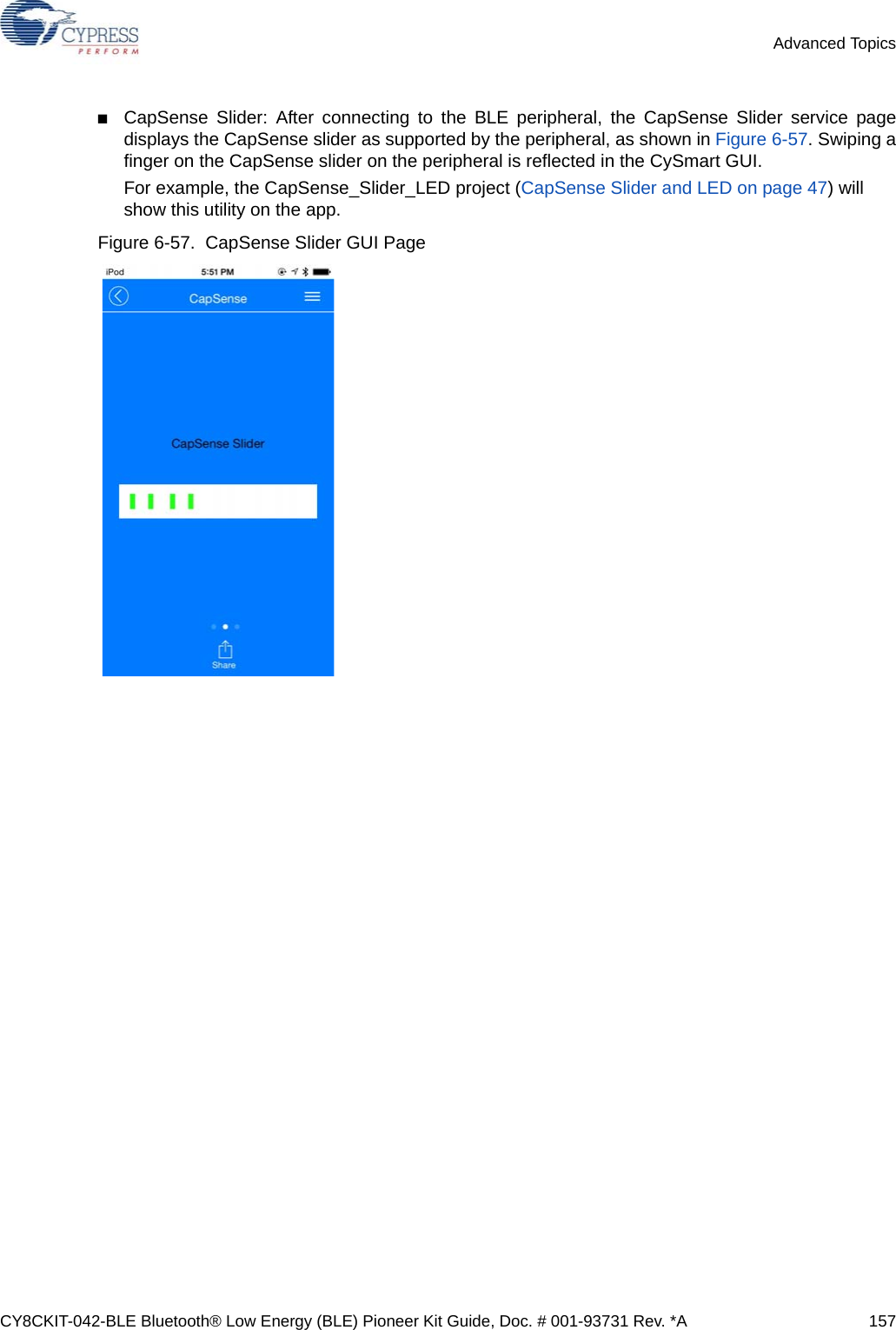
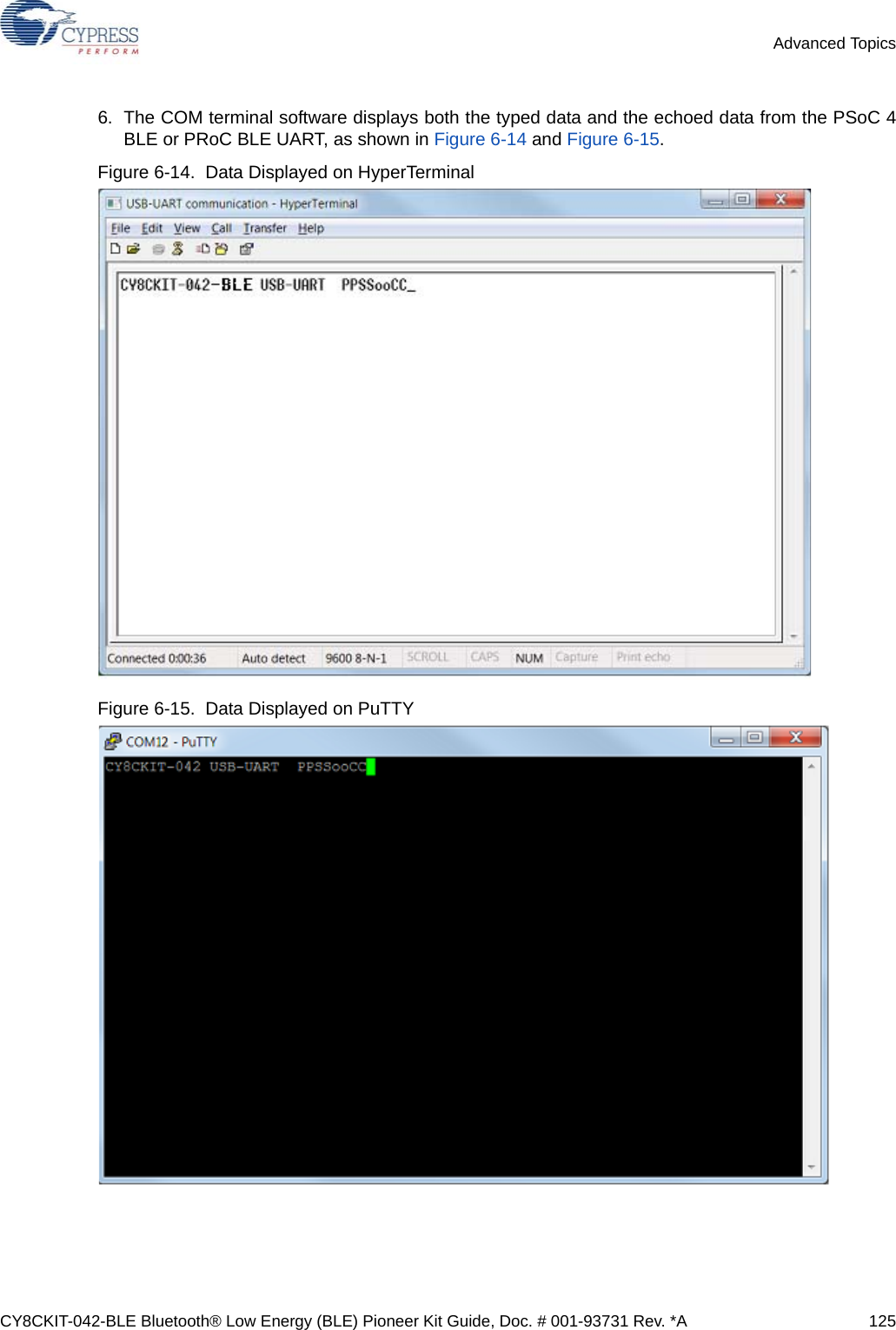
![CY8CKIT-042-BLE Bluetooth® Low Energy (BLE) Pioneer Kit Guide, Doc. # 001-93731 Rev. *A 118Advanced TopicsFigure 6-6. UART Advanced Tab Window 5. Select P1[4] for UART RX and P1[5] for UART TX in the Pins tab of <Project_Name>.cydwr, asshown in Figure 6-7. Figure 6-7. Pin Selection](https://usermanual.wiki/Cypress-Semiconductor/CY8CKIT-142.Manual-part-2/User-Guide-2483368-Page-13.png)
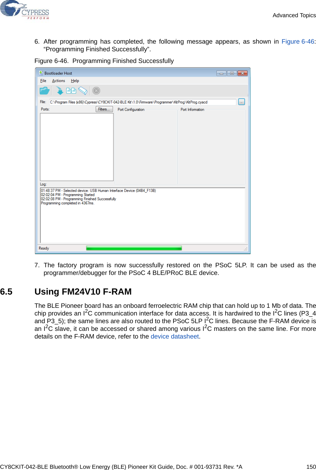
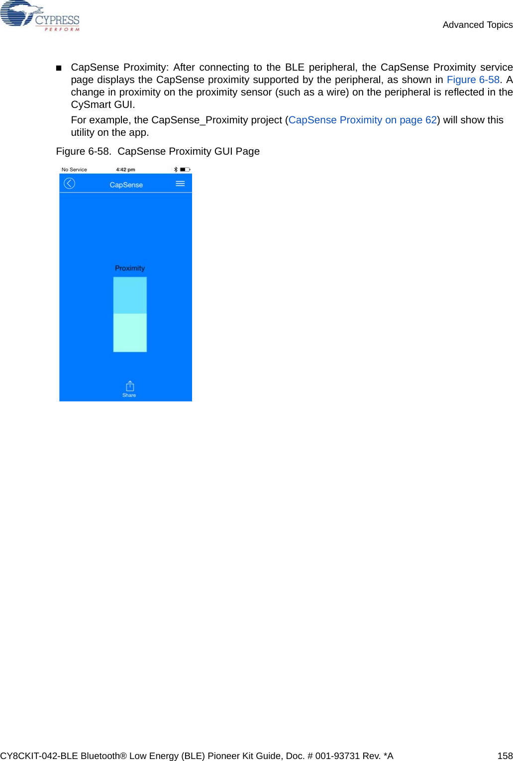
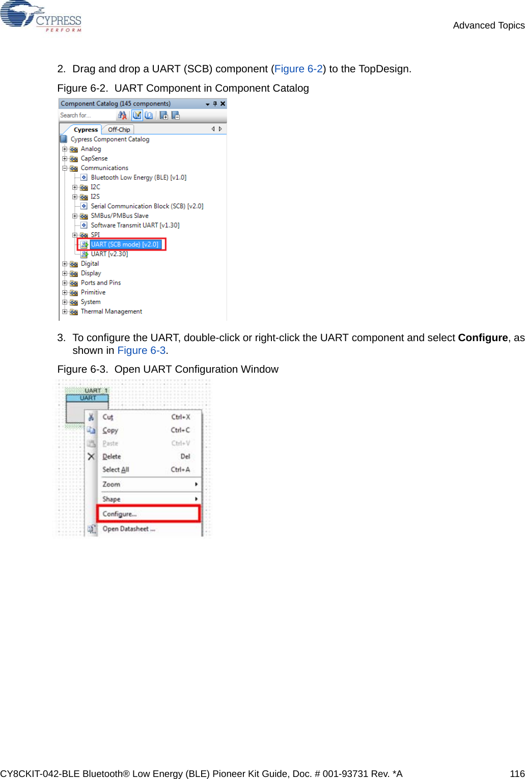
![CY8CKIT-042-BLE Bluetooth® Low Energy (BLE) Pioneer Kit Guide, Doc. # 001-93731 Rev. *A 119Advanced Topics6. Place the following code in your main.c project file. The code will echo any UART data received. int main(){ uint8 ch; /* Start SCB UART TX+RX operation */ UART_Start(); /* Transmit String through UART TX Line */UART_UartPutString("CY8CKIT-042-BLE USB-UART"); for(;;) { /* Get received character or zero if nothing has been received yet */ ch = UART_UartGetChar(); if(0u != ch) { /* Send the data through UART. This function is blocking and waits until there is an entry into the TX FIFO. */ UART_UartPutChar(ch); } }}7. Build the project by clicking Build > Build {Project Name} or [Shift][F6]. After the project is builtwithout errors and warnings, program (by choosing Debug > Program) the project to PSoC 4BLE/PRoC BLE through the PSoC 5LP USB programmer or MiniProg3.Note: UART RX and UART TX can be routed to any digital pin on PSoC 4 BLE/PRoC BLE basedon the configuration of the UART component. An SCB implementation of UART will route the RXand TX pins to one of the following subsets: (P0[0], P0[1] or P0[4], P0[5] or P1[4], P1[5] or P3[0],P3[1] or P3[4], P3[5] or P5[0], P5[1]).](https://usermanual.wiki/Cypress-Semiconductor/CY8CKIT-142.Manual-part-2/User-Guide-2483368-Page-14.png)
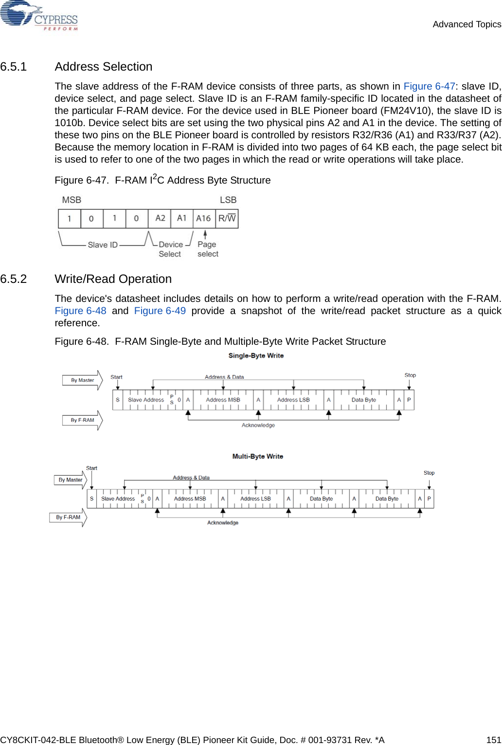
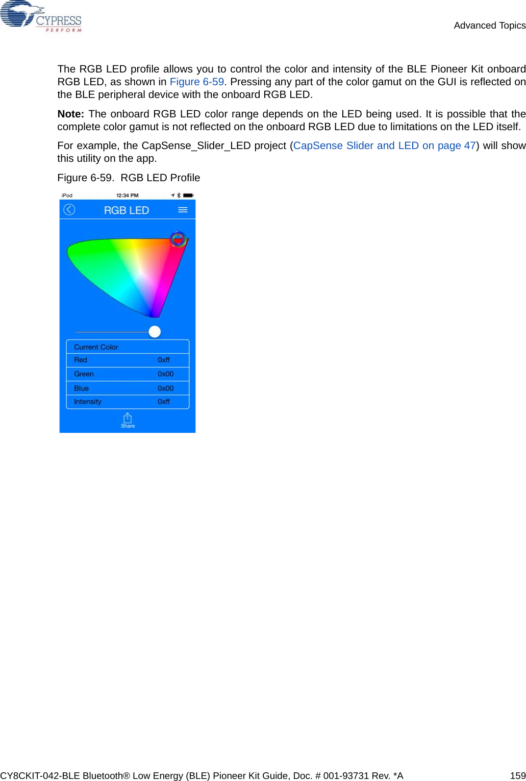
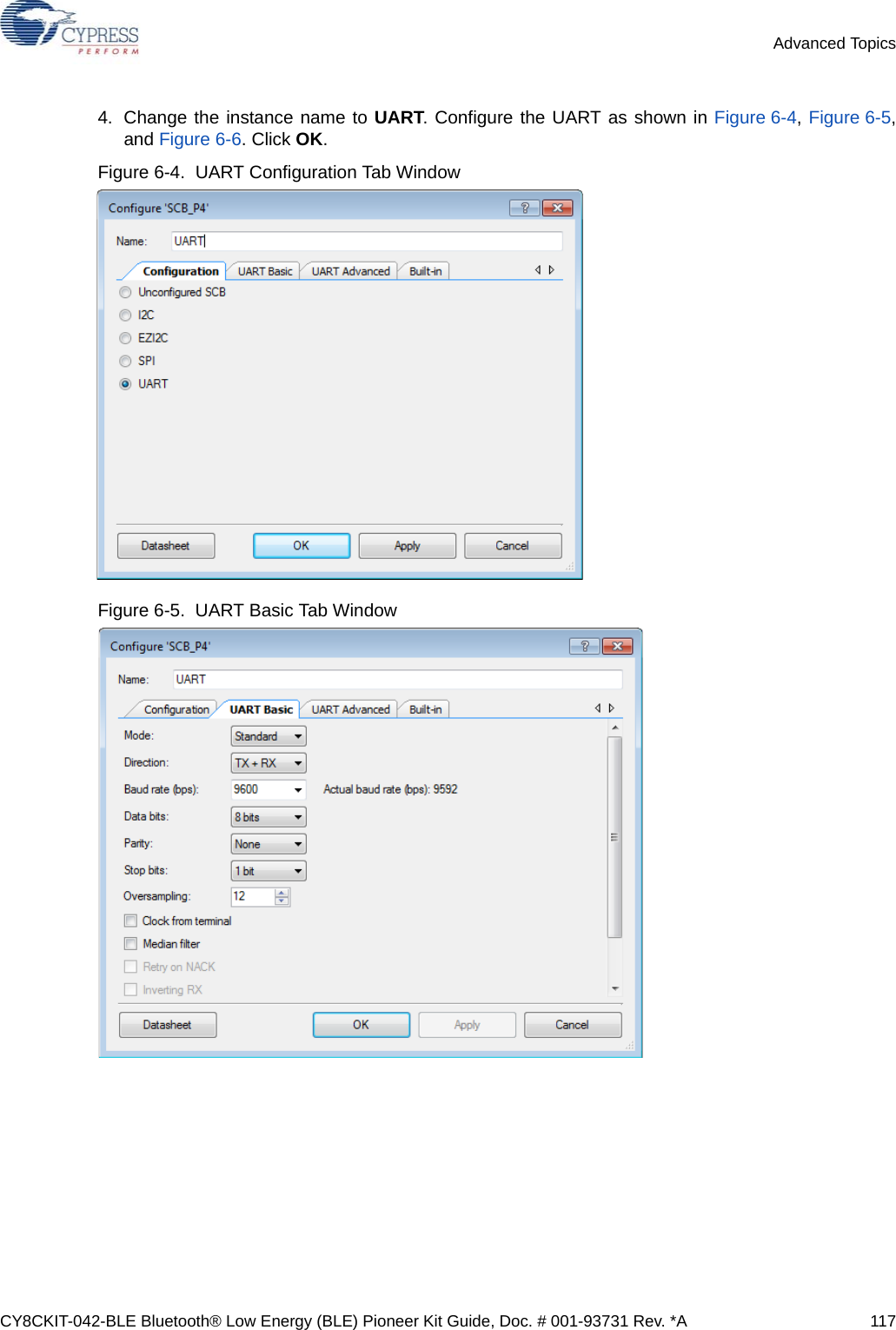
![CY8CKIT-042-BLE Bluetooth® Low Energy (BLE) Pioneer Kit Guide, Doc. # 001-93731 Rev. *A 129Advanced Topics5. Select pin P3[5] for the I2C SCL and pin P3[4] for the I2C SDA in the Pins tab of<Project_Name>.cydwr, as shown in Figure 6-21.Figure 6-21. Pin Selection_USBI2C 6. Place the following code in your main.c project file. The code will enable the PSoC 4 BLE/PRoCBLE device to transmit and receive I2C data to and from the BCP application.int main(){uint8 wrBuf[10]; /* I2C write buffer */uint8 rdBuf[10]; /* I2C read buffer */uint8 indexCntr;uint32 byteCnt;/* Enable the Global Interrupt */CyGlobalIntEnable;/* Start I2C Slave operation */I2C_Start();/* Initialize write buffer */I2C_I2CSlaveInitWriteBuf((uint8 *) wrBuf, 10);/* Initialize read buffer */I2C_I2CSlaveInitReadBuf((uint8 *) rdBuf, 10);for(;;) /* Loop forever */{/* Wait for I2C master to complete a write */](https://usermanual.wiki/Cypress-Semiconductor/CY8CKIT-142.Manual-part-2/User-Guide-2483368-Page-24.png)
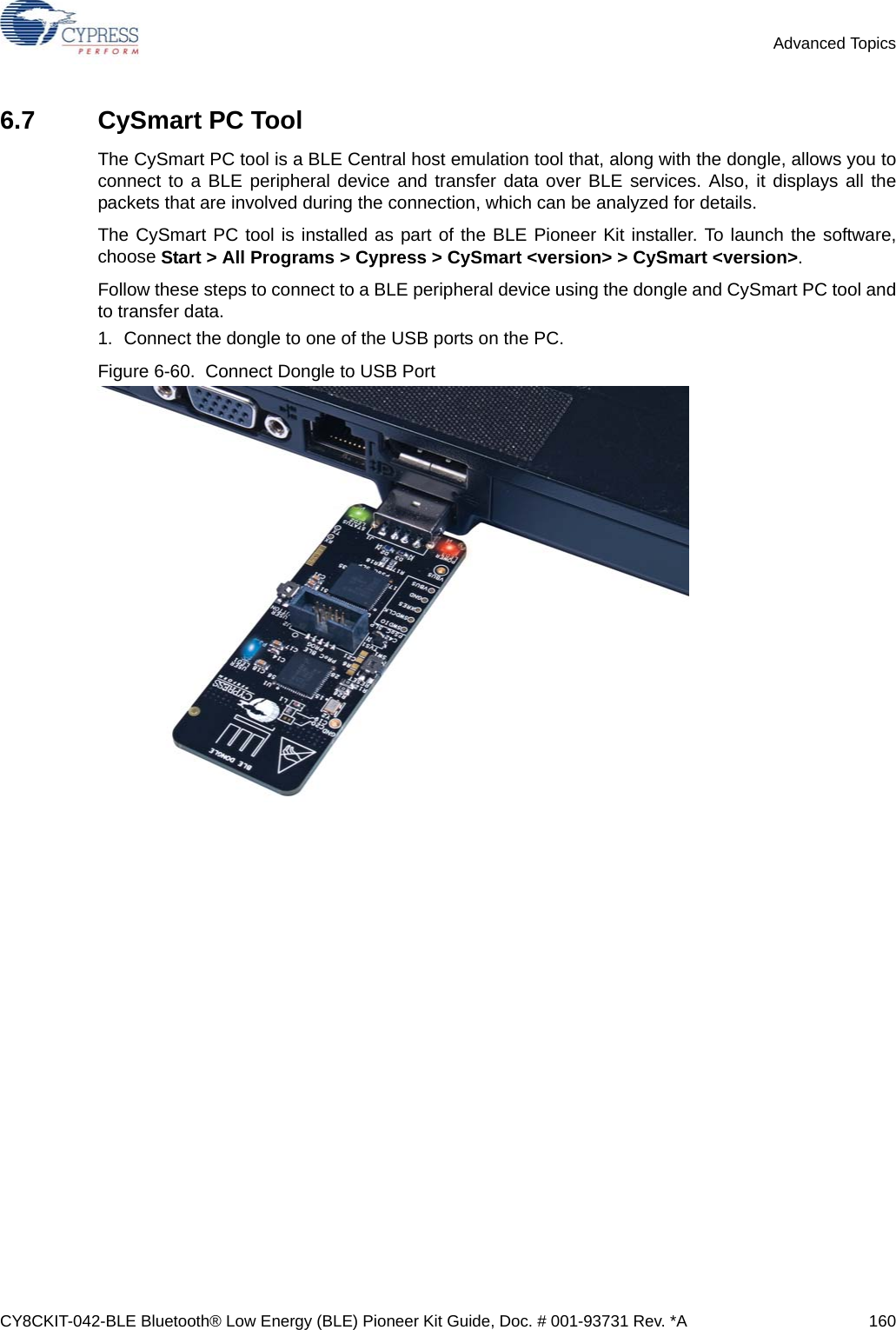
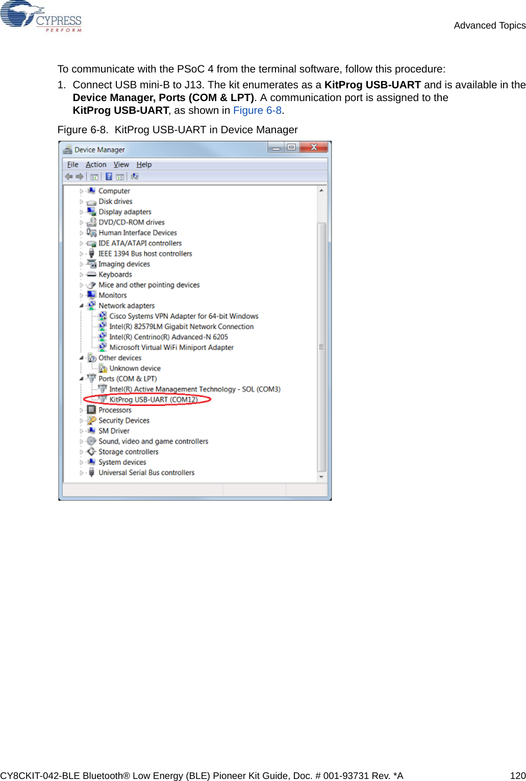
![CY8CKIT-042-BLE Bluetooth® Low Energy (BLE) Pioneer Kit Guide, Doc. # 001-93731 Rev. *A 130Advanced Topicsif(0u != (I2C_I2CSlaveStatus() & I2C_I2C_SSTAT_WR_CMPLT)){/* Read the number of bytes transferred */byteCnt = I2C_I2CSlaveGetWriteBufSize();/* Clear the write status bits*/I2C_I2CSlaveClearWriteStatus();/* Move the data written by the master to the read buffer so that the master can read back the data */for(indexCntr = 0; indexCntr < byteCnt; indexCntr++){rdBuf [indexCntr] = wrBuf[indexCntr]; /* Loop back the data to the read buffer */}/* Clear the write buffer pointer so that the next write operation will start from index 0 */I2C_I2CSlaveClearWriteBuf();/* Clear the read buffer pointer so that the next read operations starts from index 0 */I2C_I2CSlaveClearReadBuf();}/* If the master has read the data , reset the read buffer pointer to 0 and clear the read status */if(0u != (I2C_I2CSlaveStatus() & I2C_I2C_SSTAT_RD_CMPLT)){/* Clear the read buffer pointer so that the next read operations starts from index 0 */I2C_I2CSlaveClearReadBuf();/* Clear the read status bits */I2C_I2CSlaveClearReadStatus();}}}7. Build the project by choosing Build > Build Project or [Shift] [F6]. After the project is builtwithout errors and warnings, program ([Ctrl] [F5]) this code onto the PSoC 4 BLE/PRoC BLEthrough the PSoC 5LP programmer or MiniProg3.8. Open the BCP from Start > All Programs > Cypress > Bridge Control Panel <versionnumber>.9. Connect to KitProg/ under Connected I2C/SPI/RX8 Ports, as shown in Figure 6-22.](https://usermanual.wiki/Cypress-Semiconductor/CY8CKIT-142.Manual-part-2/User-Guide-2483368-Page-25.png)
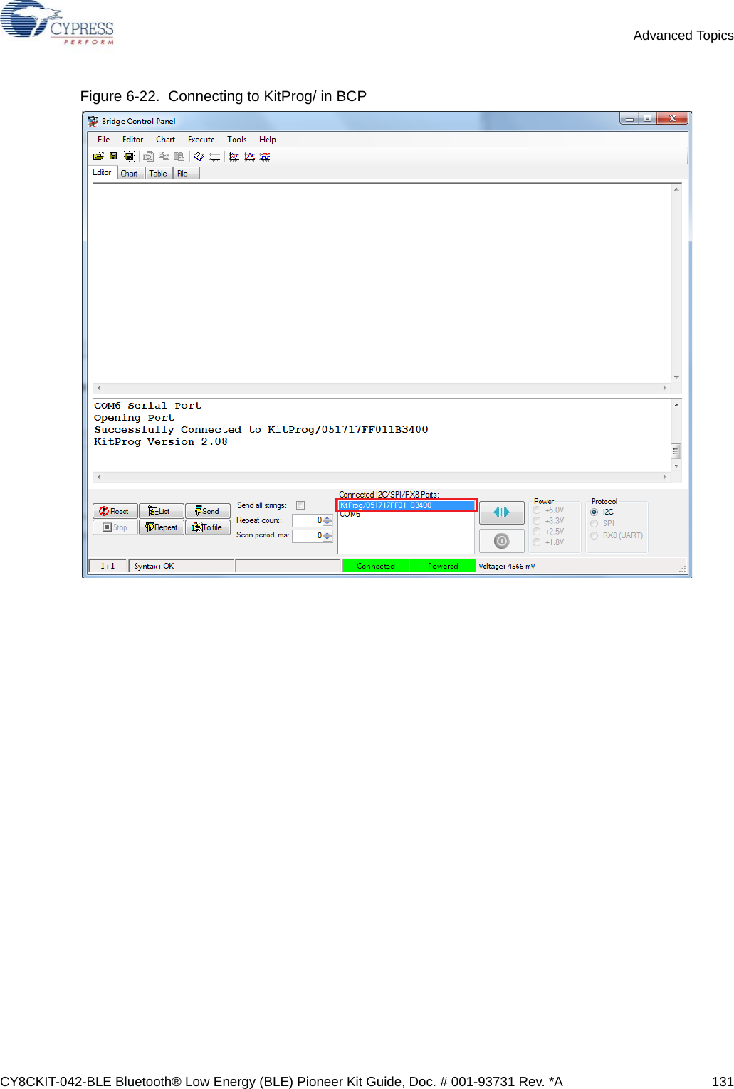
![CY8CKIT-042-BLE Bluetooth® Low Energy (BLE) Pioneer Kit Guide, Doc. # 001-93731 Rev. *A 132Advanced Topics10.Open Protocol Configuration from the Tools menu and select the appropriate I2C Speed, asshown in Figure 6-23. Make sure the I2C speed is the same as the one configured in the I2Ccomponent. Click OK to close the window.Figure 6-23. Opening Protocol Configuration Window in BCP11.From the BCP, transfer five bytes of data to the I2C device with slave address 0x08. Type thecommand shown in Figure 6-24 and press [Enter] or click the Send button in the BCP. The logshows whether the transaction was successful. A '+' indication after each byte indicates that thetransaction was successful and a '–' indicates that the transaction was a failure.Figure 6-24. Entering Commands in BCP](https://usermanual.wiki/Cypress-Semiconductor/CY8CKIT-142.Manual-part-2/User-Guide-2483368-Page-27.png)
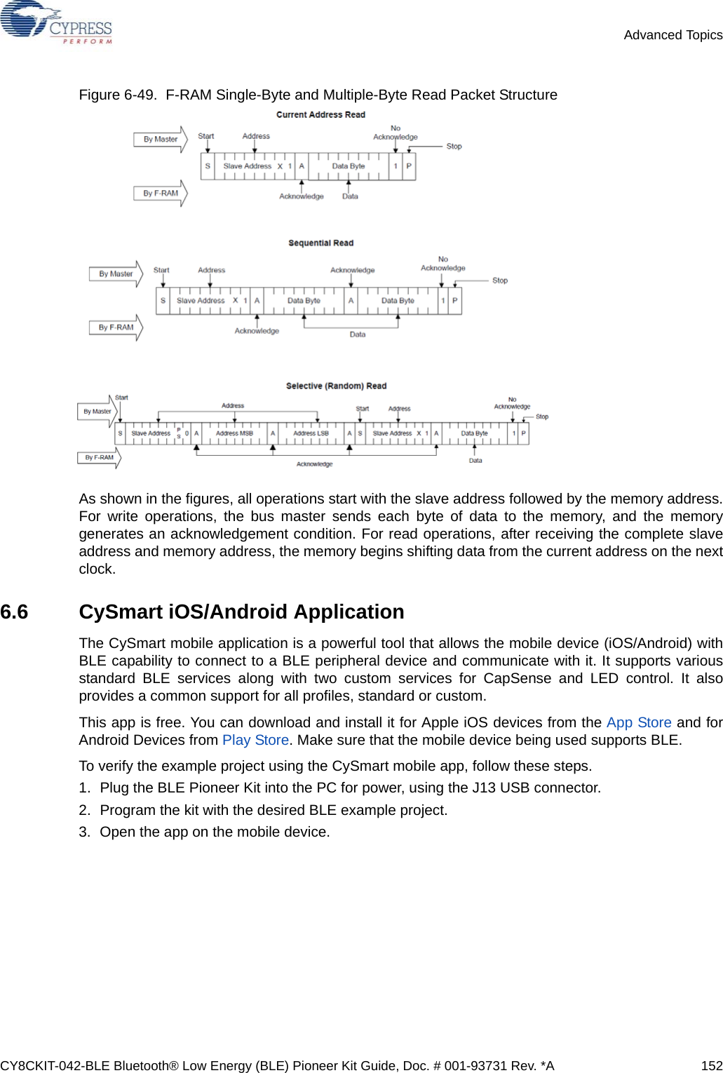
![CY8CKIT-042-BLE Bluetooth® Low Energy (BLE) Pioneer Kit Guide, Doc. # 001-93731 Rev. *A 133Advanced Topics12.From the BCP, read five bytes of data from the I2C slave device with slave address 0x08. The logshows whether the transaction was successful, as shown in Figure 6-25.Figure 6-25. Read Data Bytes from BCPNote: Refer to Help Contents under Help in BCP or press [F1] for details of I2C commands.](https://usermanual.wiki/Cypress-Semiconductor/CY8CKIT-142.Manual-part-2/User-Guide-2483368-Page-28.png)
![CY8CKIT-042-BLE Bluetooth® Low Energy (BLE) Pioneer Kit Guide, Doc. # 001-93731 Rev. *A 139Advanced Topics4. Make sure that the NVL setting of the Bootloadable project and the KitProg_Bootloader project isthe same. Figure 6-35 shows the KitProg_Bootloader.cydwr system settings. Figure 6-35. KitProg Bootloader System Settings 5. Build the project in PSoC Creator by choosing Build > Build Project or [Shift] [F6].6. To download the project onto the PSoC 5LP device, open the Bootloader Host tool, which isavailable in PSoC Creator. Choose Tools > Bootloader Host, as shown in Figure 6-36.Figure 6-36. Open Bootloader Host Tool in PSoC Creator](https://usermanual.wiki/Cypress-Semiconductor/CY8CKIT-142.Manual-part-2/User-Guide-2483368-Page-34.png)
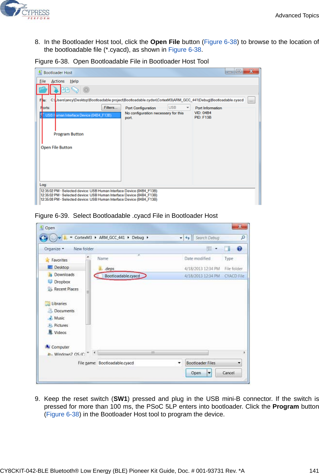
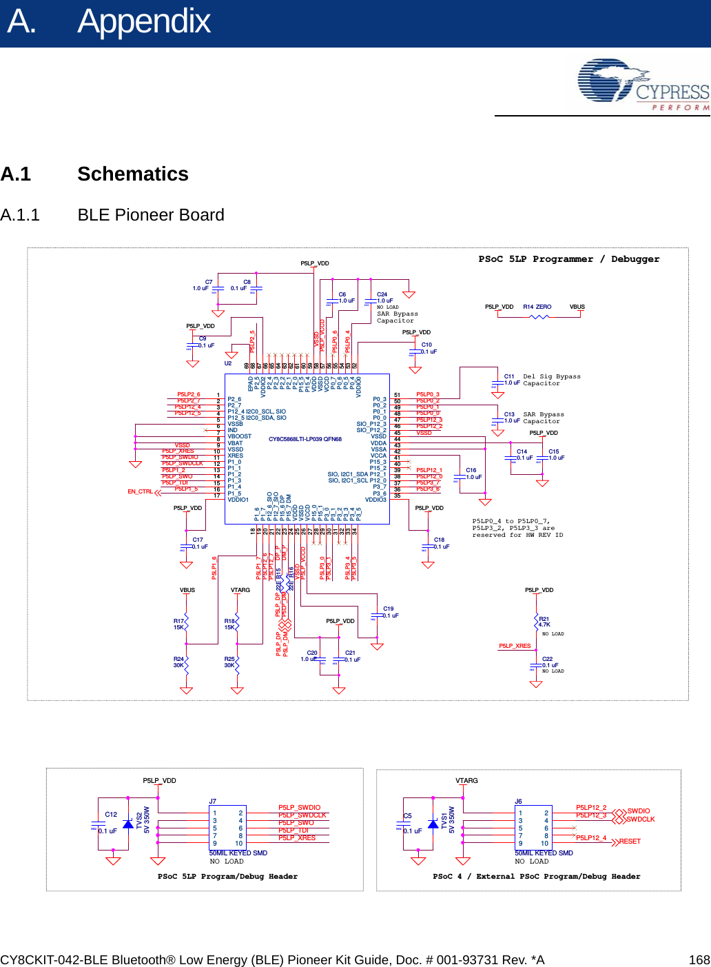
![CY8CKIT-042-BLE Bluetooth® Low Energy (BLE) Pioneer Kit Guide, Doc. # 001-93731 Rev. *A 142Advanced Topics10.If bootload is successful, the log of the tool displays “Programming Finished Successfully”;otherwise, it displays “Failed” and a reason for the failure.Notes:■The PSoC 5LP pins are brought to the PSoC 5LP GPIO header (J8). These pins are selected tosupport high-performance analog and digital projects. See PSoC 5LP GPIO Header (J8) onpage 97 for pin information.■Take care when allocating the PSoC 5LP pins for custom applications. For example, P2[0]–P2[4]are dedicated for programming the PSoC 4 BLE/PRoC BLE. See Schematics on page 168before allocating the pins.■When a custom project is programmed onto the PSoC 5LP, the initial capability of the PSoC 5LPto act as a programmer, USB-UART bridge, or USB-I2C bridge in not available.■The status LED does not function unless used by the custom project.For additional information on bootloaders, refer to Cypress application note, AN73503 - USB HIDBootloader for PSoC 3 and PSoC 5LP.](https://usermanual.wiki/Cypress-Semiconductor/CY8CKIT-142.Manual-part-2/User-Guide-2483368-Page-37.png)
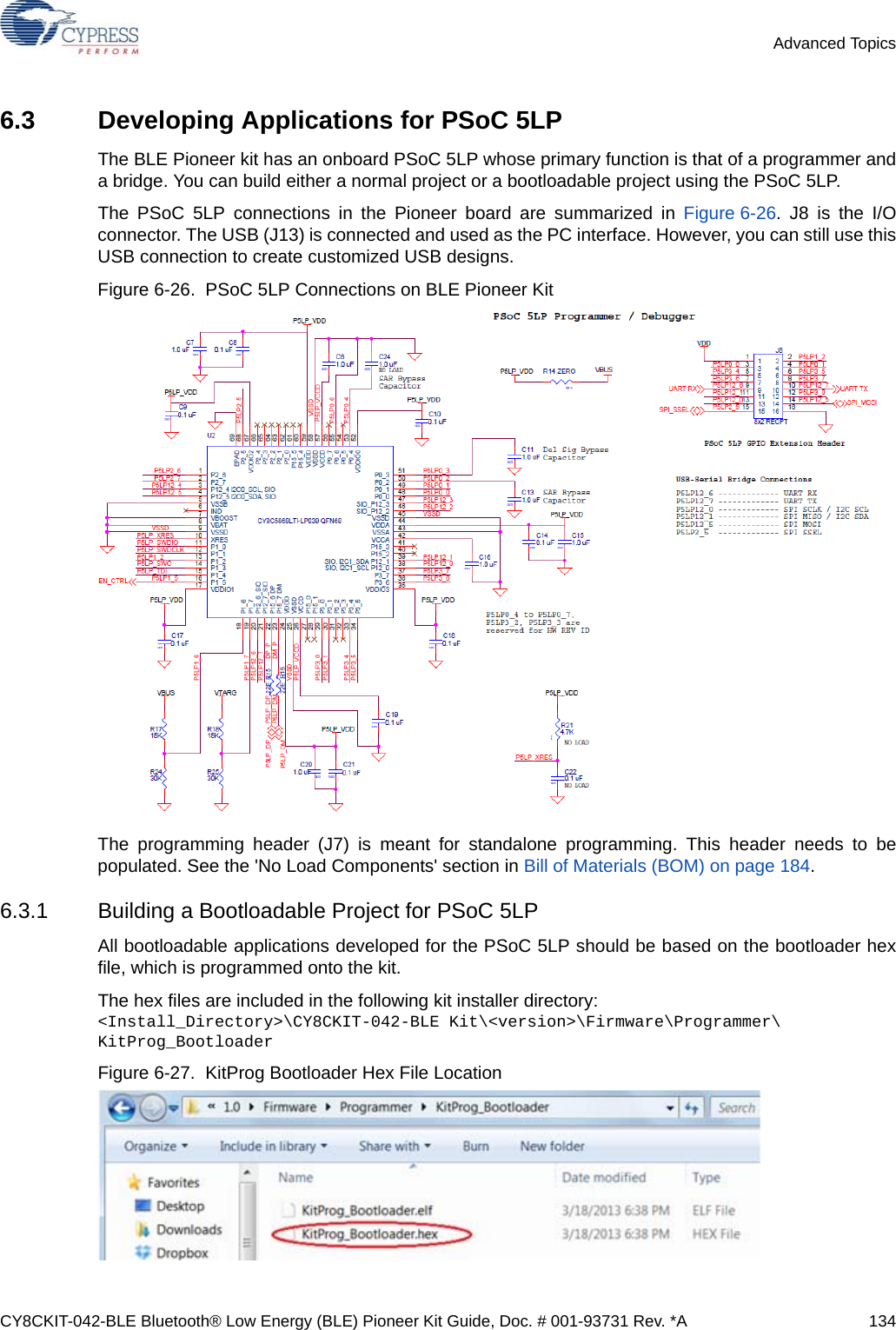
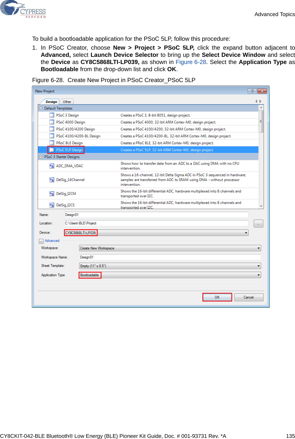
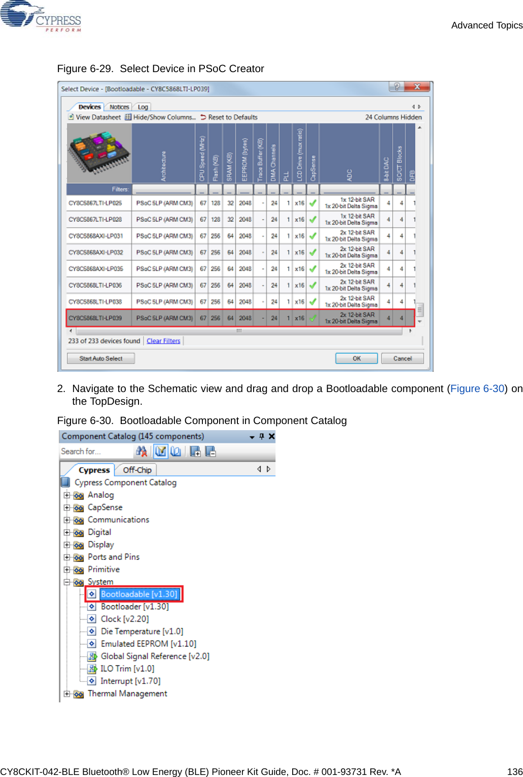
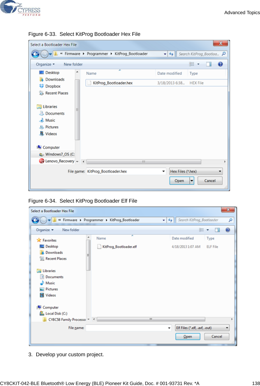
![CY8CKIT-042-BLE Bluetooth® Low Energy (BLE) Pioneer Kit Guide, Doc. # 001-93731 Rev. *A 143Advanced Topics6.3.2 Building a Normal Project for PSoC 5LPA normal project is a completely new project created for the PSoC 5LP device on the CY8CKIT-042.Here the entire flash of the PSoC 5LP is programmed, overwriting all bootloader and programmingcode. To recover the programmer, reprogram the PSoC 5LP device with the factory-set KitProg.hexfile, which is shipped with the kit installer.The KitProg.hex file is available at the following location: <Install_Directory>\CY8CKIT-042-BLE Kit\<version>\Firmware\Programmer\KitProgThis advanced functionality requires a MiniProg3 programmer, which is not included with this kit. TheMiniProg3 can be purchased from www.cypress.com/go/CY8CKIT-002.To build a normal project for the PSoC 5LP, follow these steps:1. In PSoC Creator, choose New > Project > PSoC 5LP, click the expand button adjacent toAdvanced, select Device as CY8C5868LTI-LP039, and select Application Type as Normalfrom the drop-down list, as shown in Figure 6-40.Figure 6-40. Create New Project in PSoC Creator_PSoC 5LP 2. Develop your custom project.3. Build the project in PSoC Creator by choosing Build > Build Project or pressing [Shift] [F6].](https://usermanual.wiki/Cypress-Semiconductor/CY8CKIT-142.Manual-part-2/User-Guide-2483368-Page-38.png)
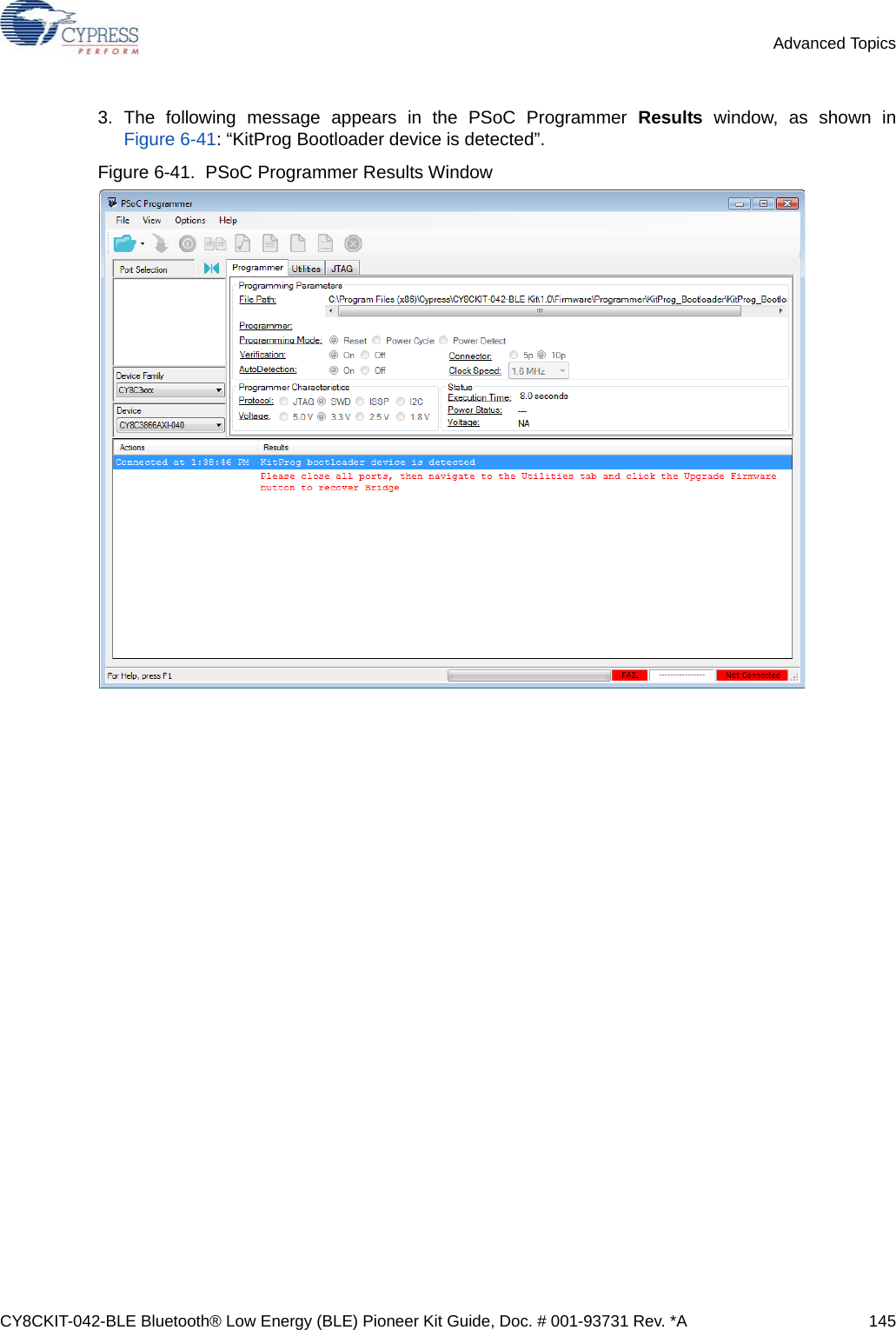
![CY8CKIT-042-BLE Bluetooth® Low Energy (BLE) Pioneer Kit Guide, Doc. # 001-93731 Rev. *A 144Advanced Topics4. Connect the 10-pin connector of MiniProg3 to the onboard 10-pin SWD debug and programmingheader J7 (which needs to be populated).5. To program the PSoC 5LP with PSoC Creator, choose Debug > Program or press [Ctrl] [F5]. Ifthe Programming window appears and shows MiniProg3 and the selected device in the projectunder it (CY8C5868LTI-LP039); click on the device and click Connect to program.Notes:■The 10-pin SWD debug and programming header (J7) is not populated. See the 'No LoadComponents' section of A.3 Bill of Materials (BOM) for details.■The PSoC 5LP pins are brought to the PSoC 5LP GPIO header (J8). These pins are selected tosupport high-performance analog and digital projects. See PSoC 5LP GPIO Header (J8) onpage 97 for pin information.■Take care when allocating the PSoC 5LP pins for custom applications. For example, P2[0]–P2[4]are dedicated for programming the PSoC 4. Refer to A.1 Schematics before allocating the pins.■When a normal project is programmed onto the PSoC 5LP, the initial capability of the PSoC 5LPto act as a programmer, USB-UART bridge, or USB-I2C bridge is not available.■The status LED does not function unless it is used by the custom project.6.4 PSoC 5LP Factory Program Restore InstructionsThe BLE Pioneer Kit features a PSoC 5LP device that comes factory-programmed as the onboardprogrammer and debugger for the PSoC 4 BLE/PRoC BLE device.In addition to creating applications for the BLE device, you can also create custom applications forthe PSoC 5LP device on this kit. For details, see section Developing Applications for PSoC 5LP onpage 134. Reprogramming or bootloading the PSoC 5LP device with a new flash image willoverwrite the factory program and forfeit the ability to use the PSoC 5LP device as a programmer/debugger for the BLE device. Follow the instructions to restore the factory program on the PSoC5LP and enable the programmer/debugger functionality.6.4.1 PSoC 5LP is Programmed with a Bootloadable ApplicationIf the PSoC 5LP is programmed with a bootloadable application, restore the factory program byusing one of the following two methods.6.4.1.1 Restore PSoC 5LP Factory Program Using PSoC Programmer1. Launch PSoC Programmer 3.21.1 or later from Start > Cypress > PSoC Programmer.2. Configure the BLE Pioneer Kit in service mode. To do this, while holding down the reset button(SW1 Reset), plug in the BLE Pioneer Kit to the computer using the included USB cable (USB Ato mini-B). This puts the PSoC 5LP into service mode, which is indicated by the blinking greenstatus LED.](https://usermanual.wiki/Cypress-Semiconductor/CY8CKIT-142.Manual-part-2/User-Guide-2483368-Page-39.png)