Cypress Semiconductor CY8CKIT-142 CY8CKIT-142 PSoC 4 BLE Module User Manual Manual part 1
Cypress Semiconductor CY8CKIT-142 PSoC 4 BLE Module Manual part 1
UserManual.wiki
>
Cypress Semiconductor
>
CY8CKIT-142 User Manual
>
Manual part 1
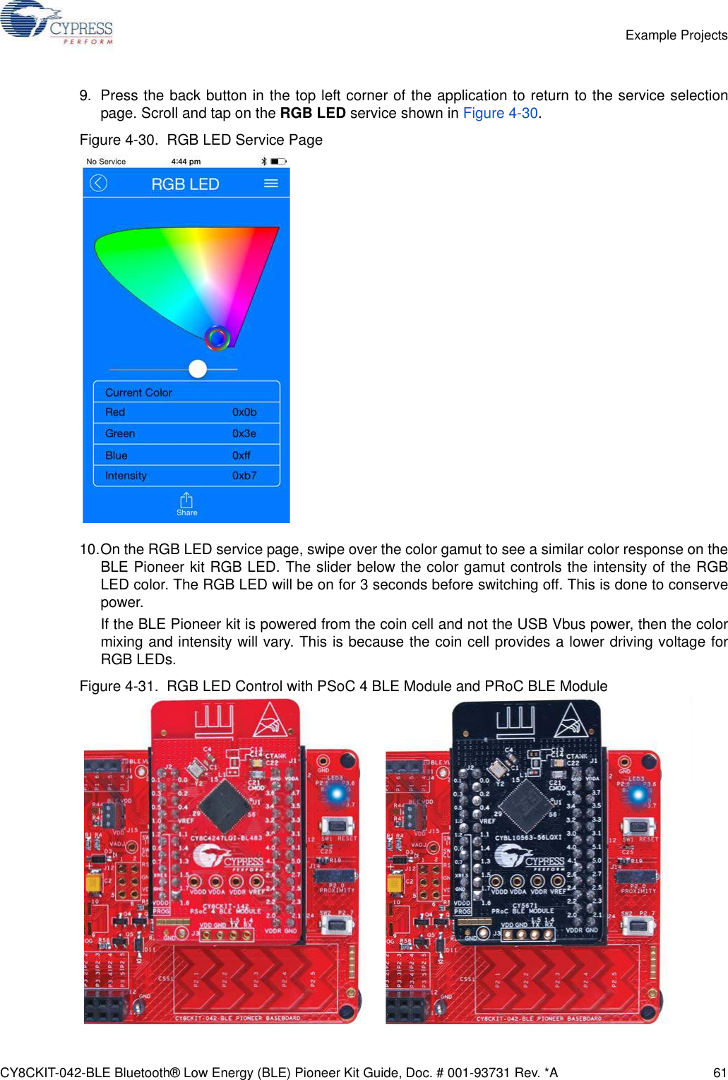
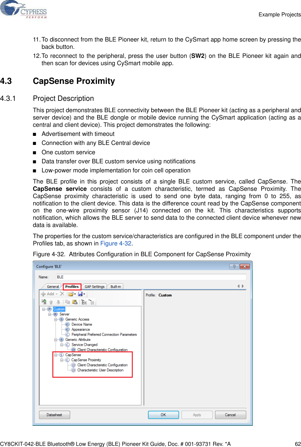
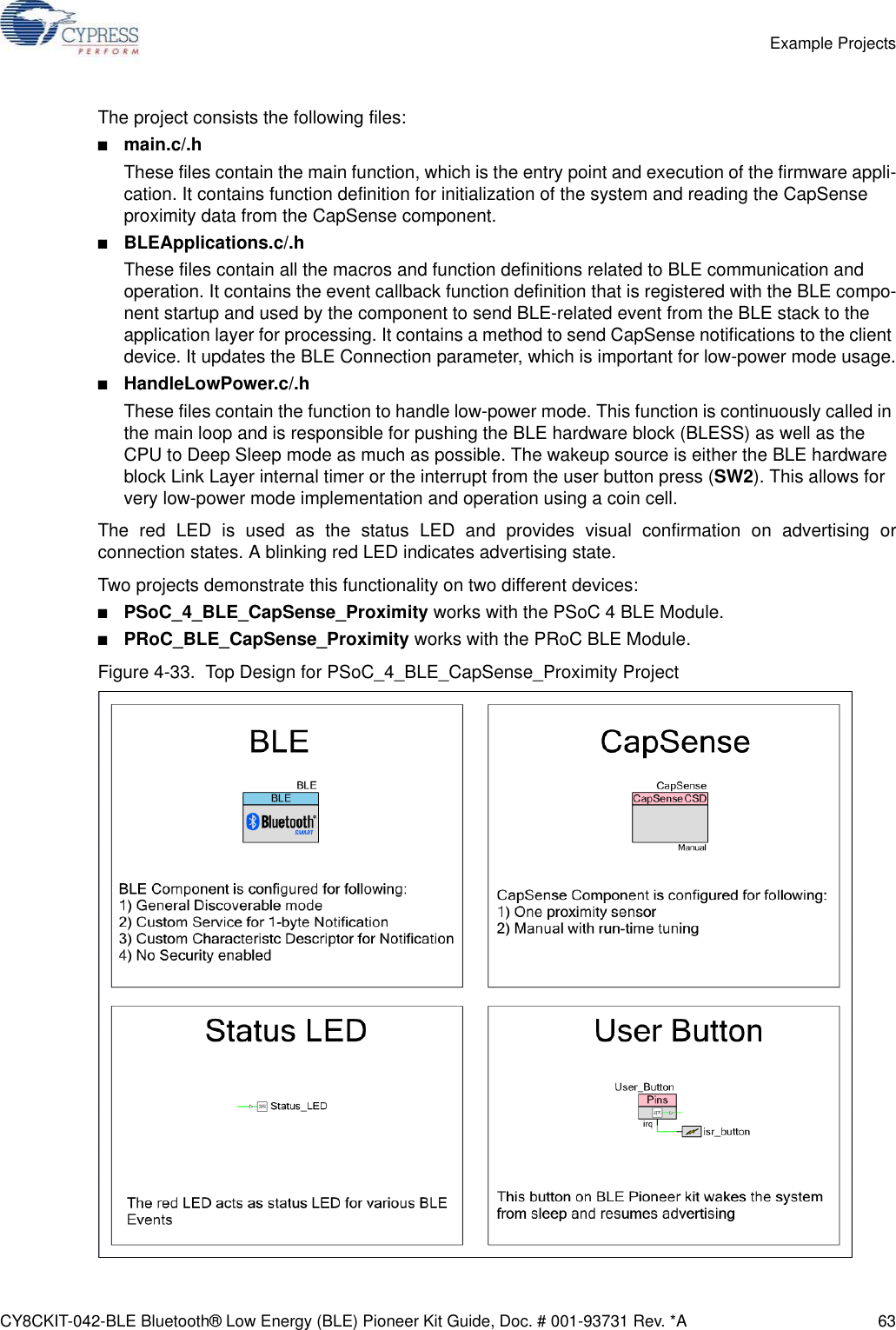
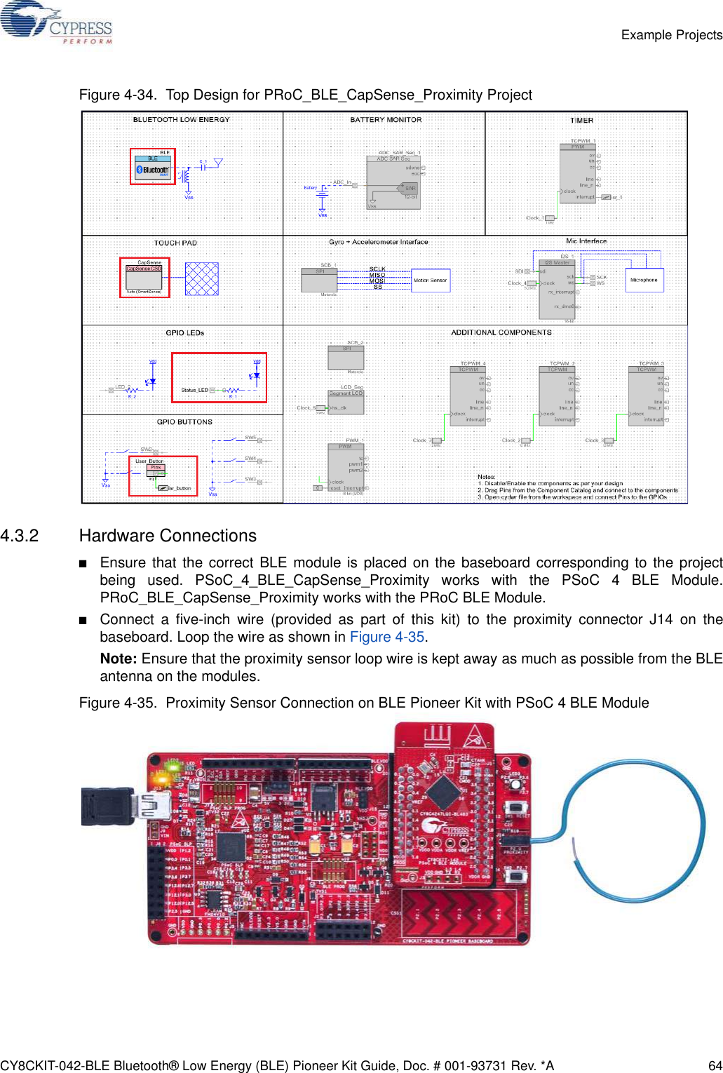
Contents
1.
Manual part 1
2.
Manual part 2
Manual part 1
Navigation menu
Upload a User Manual
Namespaces
Wiki Guide
HTML
PDF
Info
Views
User Manual
Discussion / Help
Navigation
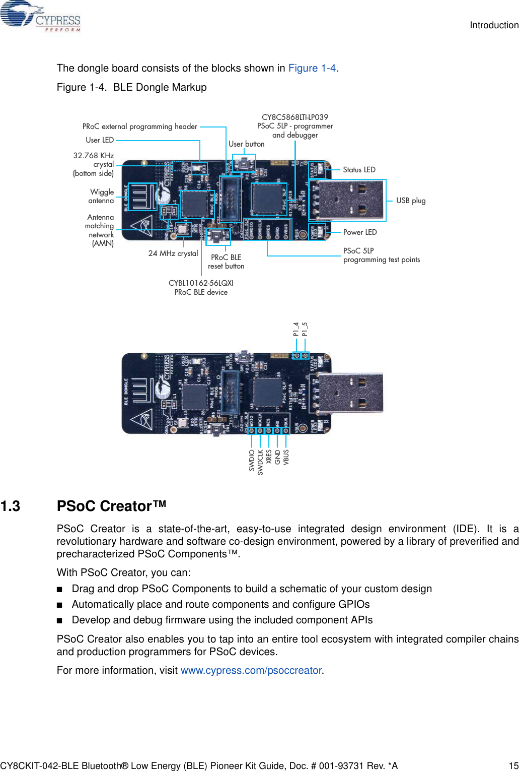
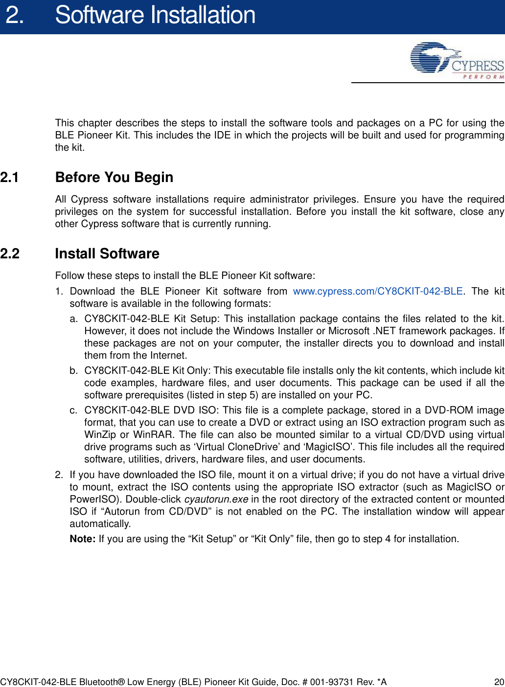
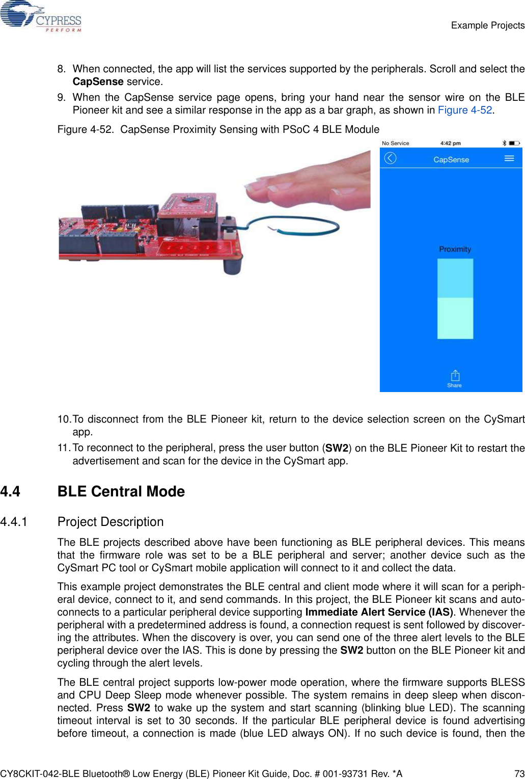
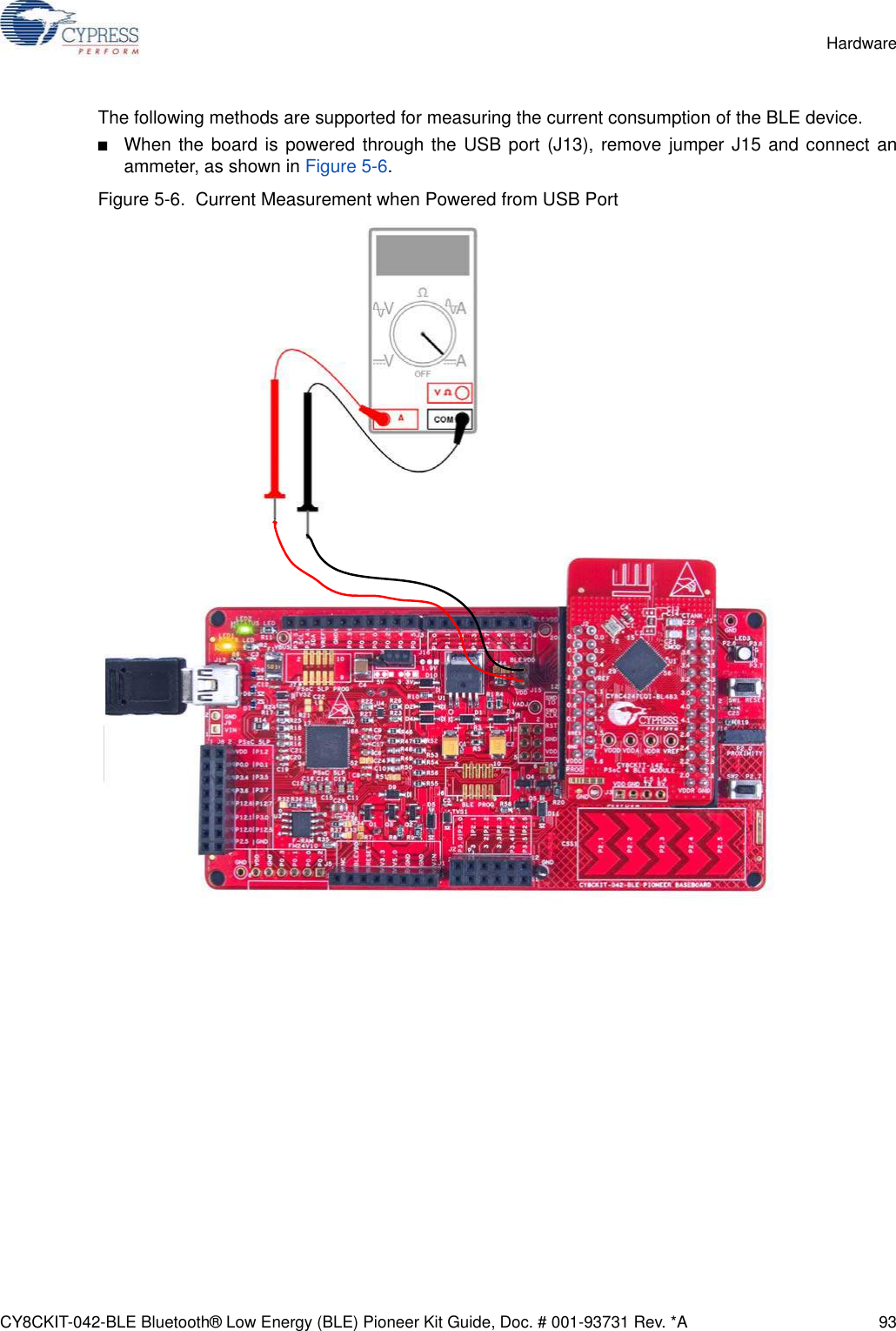
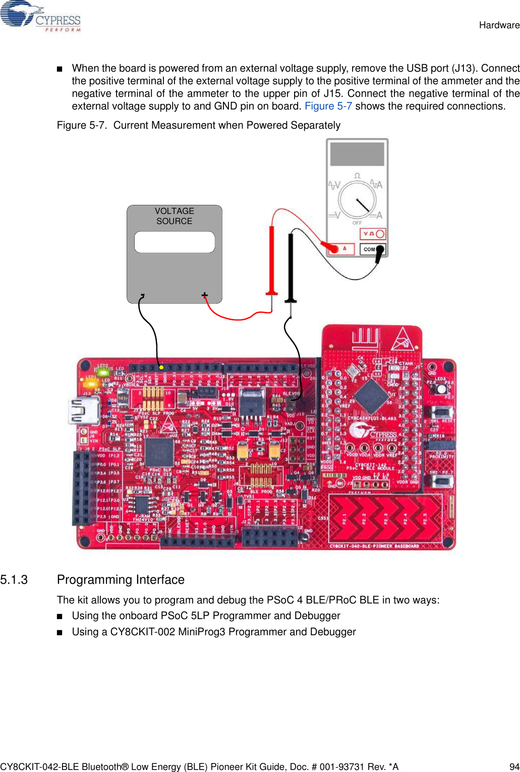
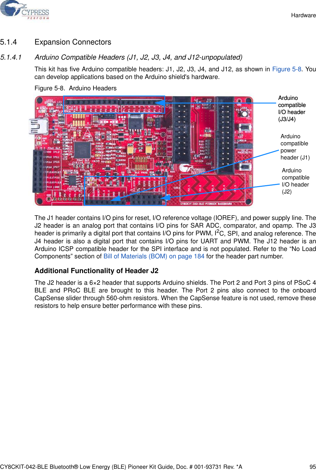
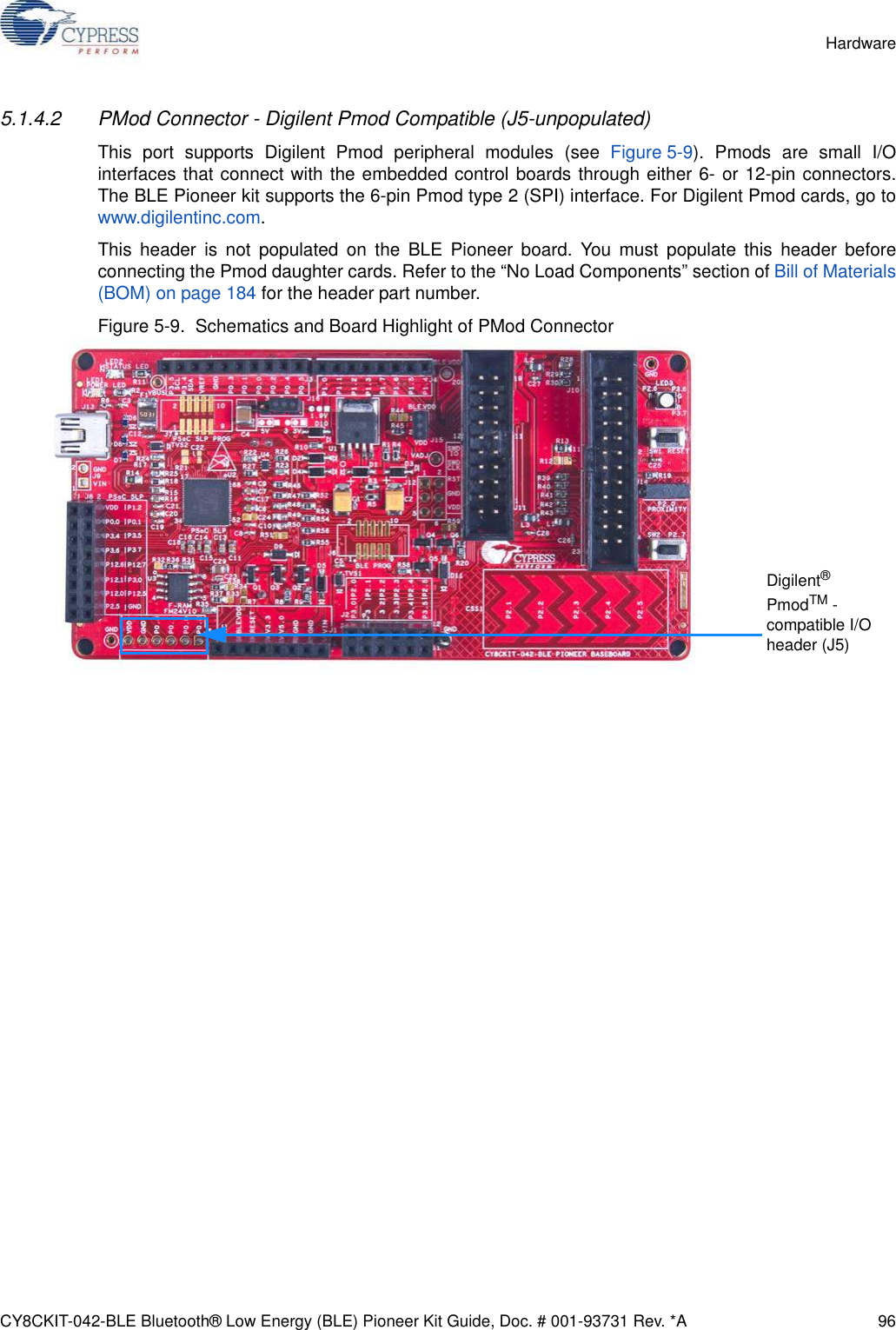
![CY8CKIT-042-BLE Bluetooth® Low Energy (BLE) Pioneer Kit Guide, Doc. # 001-93731 Rev. *A 18Introduction1.5.7 Other Related Resources■Digilent PMod: www.digilentinc.com/pmods/■Arduino: http://arduino.cc/en/Main/ArduinoBoardUno1.6 Technical SupportFor assistance, go to our support web page, www.cypress.com/support, or contact our customersupport at +1 (800) 541-4736 Ext. 2 (in the USA) or +1 (408) 943-2600 Ext. 2 (International).1.7 Documentation ConventionsTable 1-1. Document Conventions for GuidesConvention UsageCourier New Displays file locations, user entered text, and source code:C:\...cd\icc\Italics Displays file names and reference documentation:Read about the sourcefile.hex file in the PSoC Creator User Guide.[Bracketed, Bold]Displays keyboard commands in procedures:[Enter] or [Ctrl] [C]File > Open Represents menu paths:File > Open > New ProjectBold Displays commands, menu paths, and icon names in procedures:Click the File icon and then click Open.Times New Roman Displays an equation:2 + 2 = 4Text in gray boxes Describes cautions or unique functionality of the product.](https://usermanual.wiki/Cypress-Semiconductor/CY8CKIT-142.Manual-part-1/User-Guide-2483367-Page-18.png)
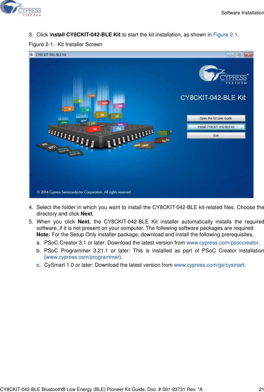
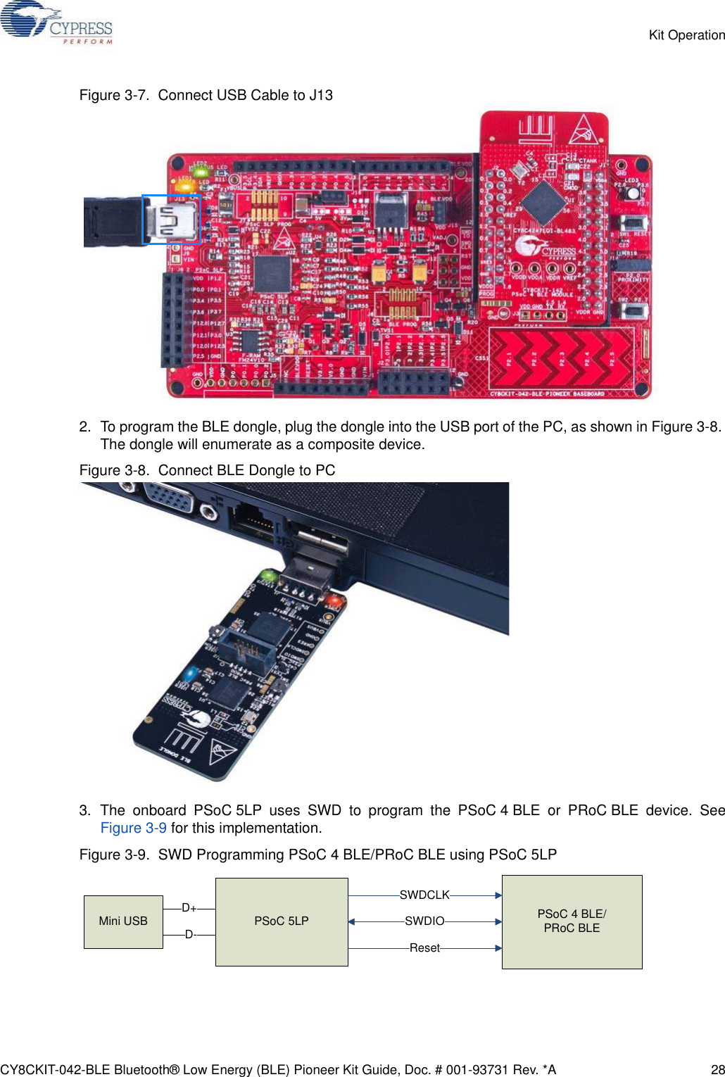
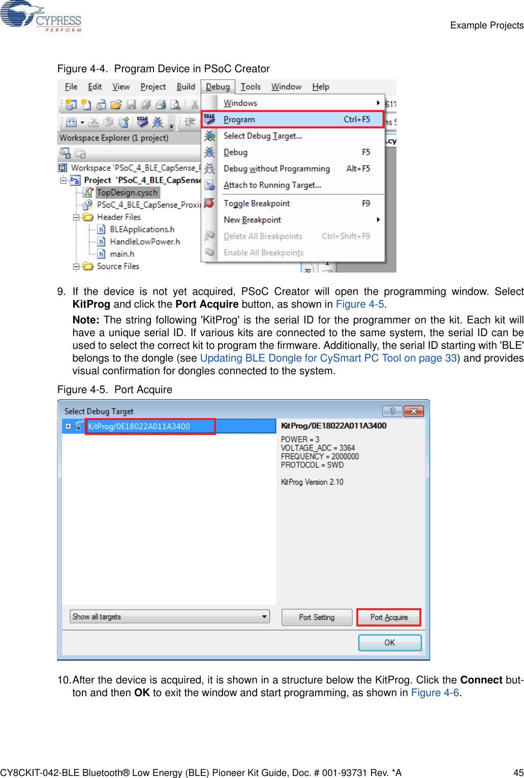
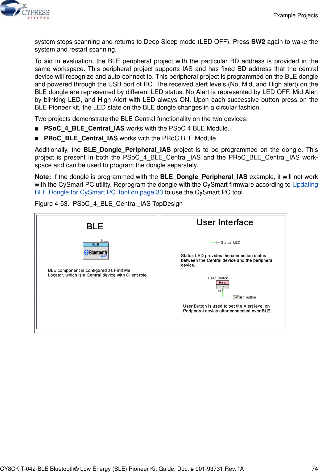
![CY8CKIT-042-BLE Bluetooth® Low Energy (BLE) Pioneer Kit Guide, Doc. # 001-93731 Rev. *A 29Kit Operation4. To load the desired example project, open PSoC Creator and go to File > Open > Project/Workspace. This will provide the option to browse to and open your saved project.5. Build the project by choosing Build > Build <Project Name> or [Shift] [F6], as shown inFigure 3-10.Figure 3-10. Build an Example Project6. If there are no errors during build, program the firmware into the kit by choosing Debug >Program or pressing [Ctrl] [F5], as shown in Figure 3-11. This will program the device on theBLE Pioneer Kit/BLE dongle and it will be ready for use. If debugging is needed on the project, goto step 6. Figure 3-11. Programming Device From PSoC Creator7. To debug the project using PSoC Creator, choose Debug > Debug or press [F5].8. When the project is built and programmed into the device on the BLE Pioneer kit/BLE dongle,PSoC Creator will enter the Debug mode; you can use it to debug your application. For moredetails on using the debug features, see the Cypress application note Getting Started with PSoC4 BLE.](https://usermanual.wiki/Cypress-Semiconductor/CY8CKIT-142.Manual-part-1/User-Guide-2483367-Page-29.png)
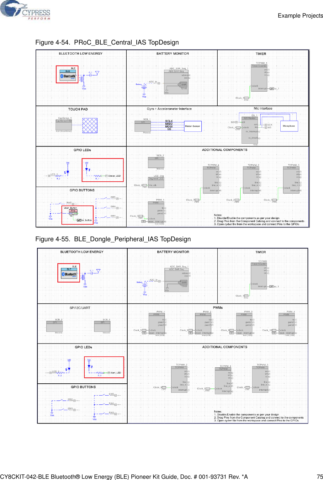
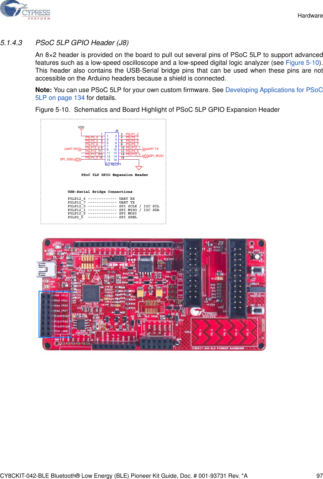
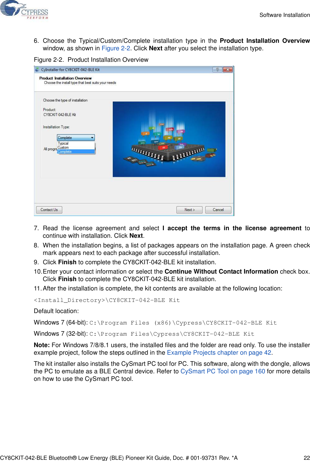
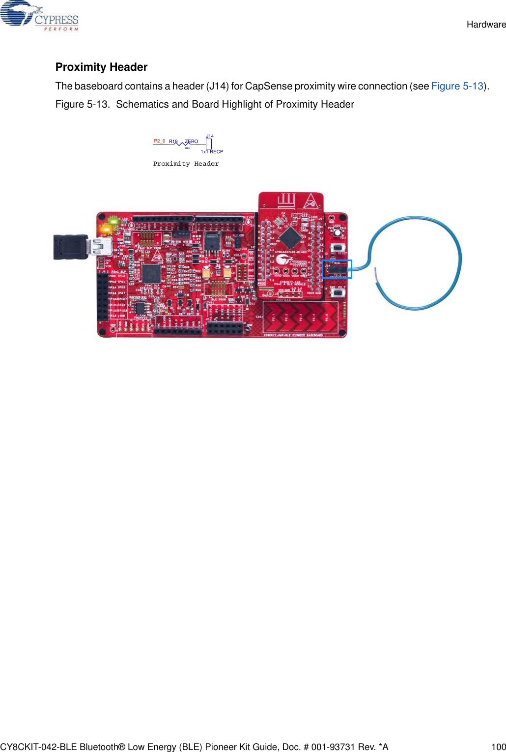
![CY8CKIT-042-BLE Bluetooth® Low Energy (BLE) Pioneer Kit Guide, Doc. # 001-93731 Rev. *A 99Hardware5.1.6 CapSense Circuit5.1.6.1 CapSense SliderThe kit has a five-segment linear capacitive touch slider, which is connected to the BLE module pins(see Figure 5-12). The CMOD and CTANK capacitors are required for CapSense functionality andare provided on the BLE modules (see BLE Module Board on page 106). A 2.2-nF capacitor ispresent on the CMOD pin, P4[0], for CapSense operation. This kit also supports CapSense designsthat enable waterproofing. On this kit, the connection of the shield to the pin or to ground is made byresistors R12 and R13, respectively. By default, R13 is mounted on the board, which connects theshield to ground. Populate R12 and remove R13 when evaluating waterproofing designs, which willconnect the shield to the designated pin, P1[6].Figure 5-12. Schematics and Board Highlight of CapSense Slider and Shield Setting](https://usermanual.wiki/Cypress-Semiconductor/CY8CKIT-142.Manual-part-1/User-Guide-2483367-Page-99.png)
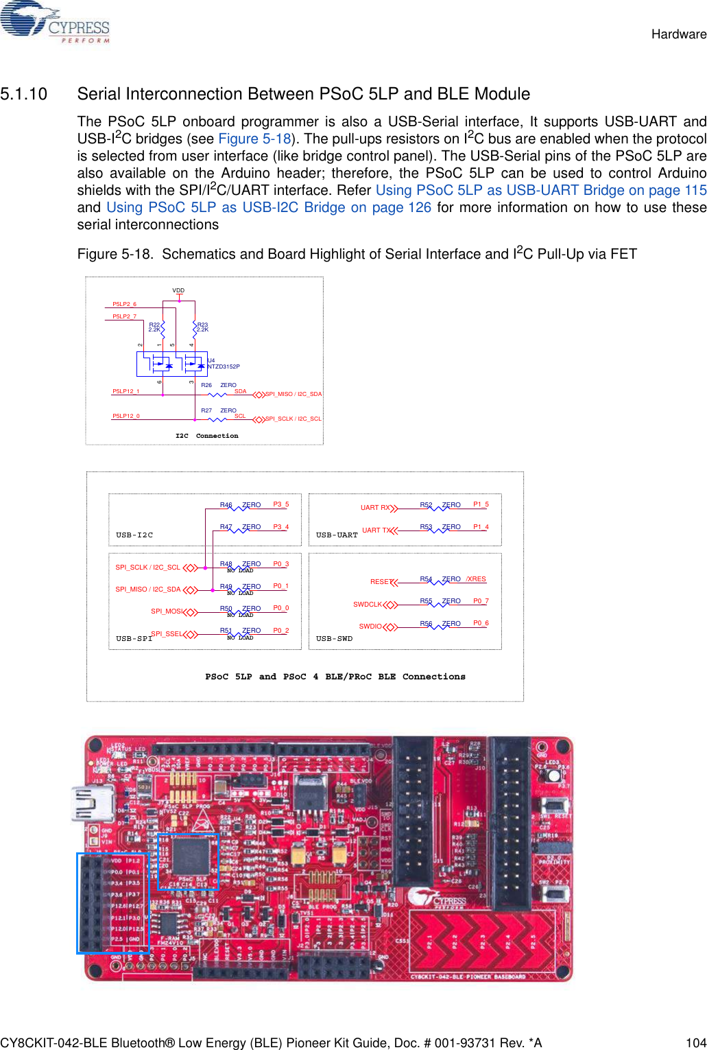
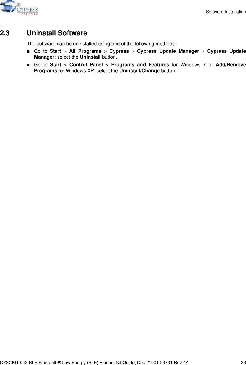
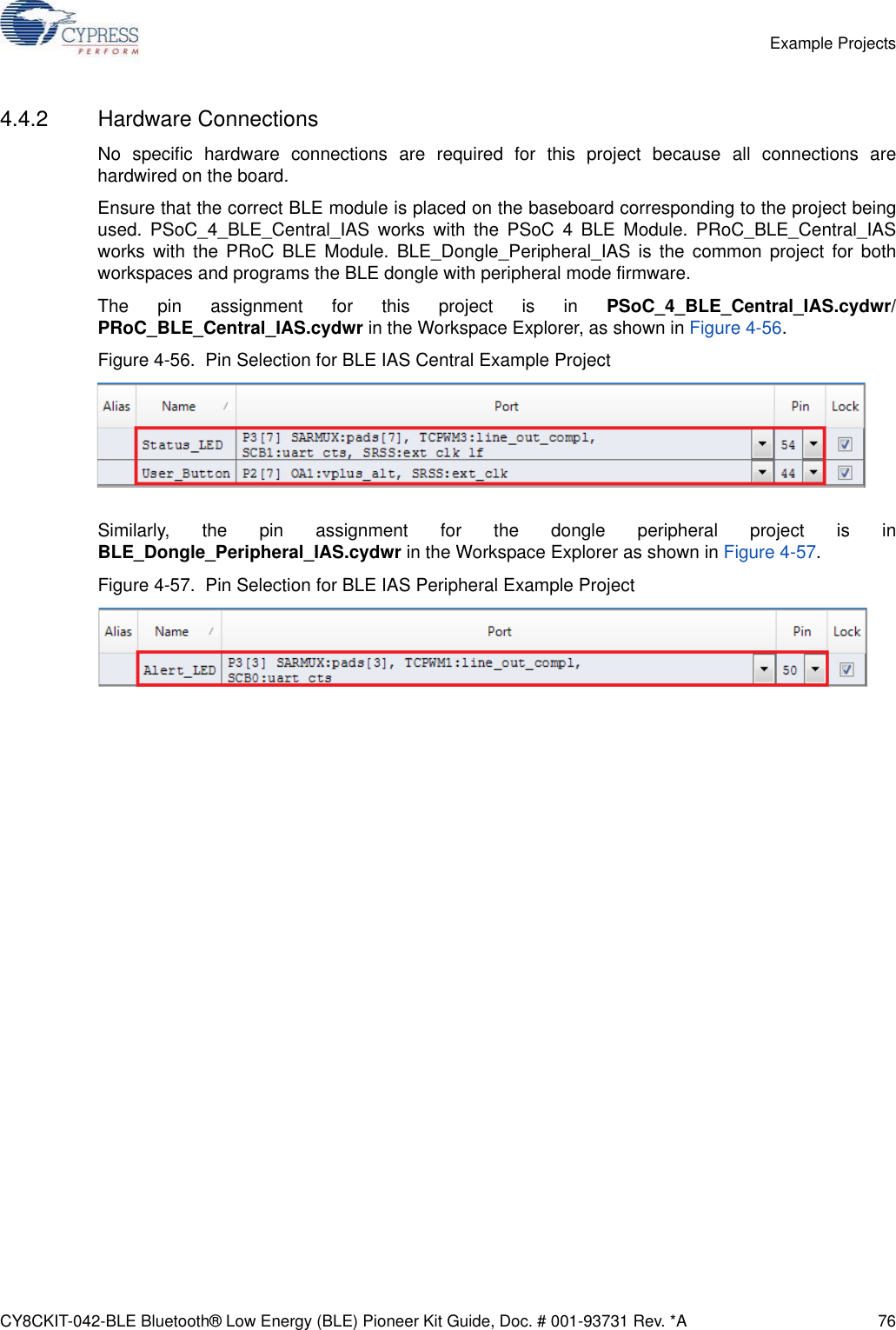
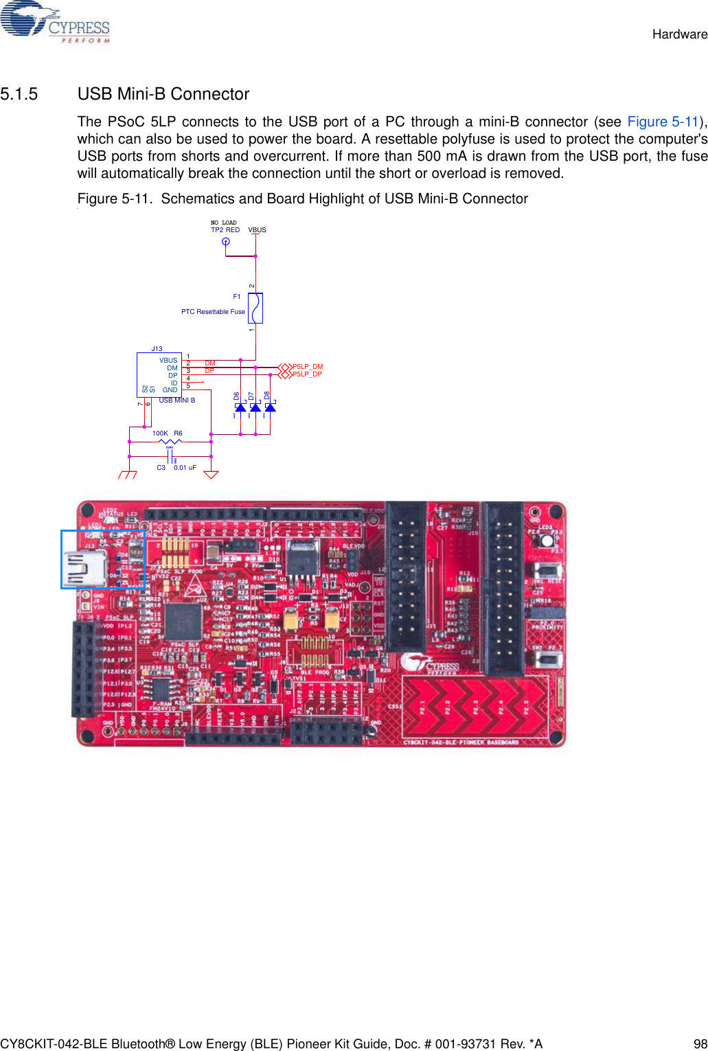
![CY8CKIT-042-BLE Bluetooth® Low Energy (BLE) Pioneer Kit Guide, Doc. # 001-93731 Rev. *A 102Hardware5.1.8 Push ButtonsThe board contains a reset push button and a user push button, as shown in Figure 5-16. The resetbutton is connected to the XRES pin of BLE and is used to reset the BLE device. The user button isconnected to P2[7] of the BLE device. Both the push buttons connect to ground on activation (activelow).Figure 5-16. Schematics and Board Highlight of Reset Button and User Push ButtonRESET USER SWITCHP2_7/XRES/XRES0402C250.1 uFSW2EVQ-PE105K1 2SW1EVQ-PE105K1 2RESET (SW1)User Button (SW2)](https://usermanual.wiki/Cypress-Semiconductor/CY8CKIT-142.Manual-part-1/User-Guide-2483367-Page-102.png)
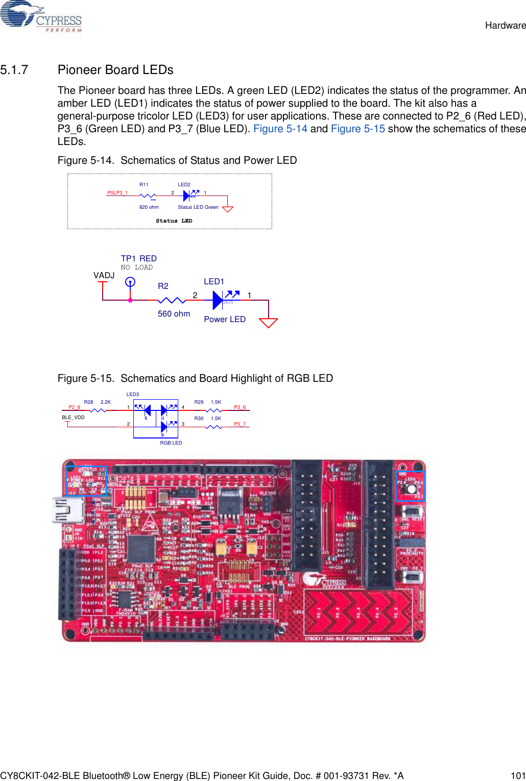
![CY8CKIT-042-BLE Bluetooth® Low Energy (BLE) Pioneer Kit Guide, Doc. # 001-93731 Rev. *A 103Hardware5.1.9 Cypress Ferroelectric RAM (F-RAM)The baseboard contains an F-RAM device (FM24V10) (see Figure 5-17) that can be accessedthrough I2C lines P5[0] and P5[1] of the PSoC 4 BLE/PRoC BLE device. The F-RAM is 1-Mbit(128 KB) with an I2C speed up to 1 Mbps. The I2C slave address of the F-RAM device is seven bitswide, and the LSB two bits are configurable through physical pins and are hardwired to 00 on theboard. By default, the address of the F-RAM device used on the board is 0x50. This address can bemodified by changing the R32/R36 and R33/R37 pairs. The operating voltage range of the F-RAM isbetween 2 V and 3.6 V. To prevent the application of 5 V from the adjustable LDO regulator on theboard, a MOSFET based protection circuit similar to the one used for the 3.3-V rail is connectedbetween the output of the regulator and the VDD pin of the F-RAM. The protection circuit cuts off thepower to the F-RAM when the output of the regulator is greater than 3.6 V.Figure 5-17. Schematics and Board Highlight of F-RAM](https://usermanual.wiki/Cypress-Semiconductor/CY8CKIT-142.Manual-part-1/User-Guide-2483367-Page-103.png)