Cypress Semiconductor CY5676A Bluetooth Device User Manual 3
Cypress Semiconductor Bluetooth Device 3
UserManual.wiki
>
Cypress Semiconductor
>
CY5676A User Manual
>
User manual3
Contents
1.
User manual1
2.
User manual2
3.
User manual3
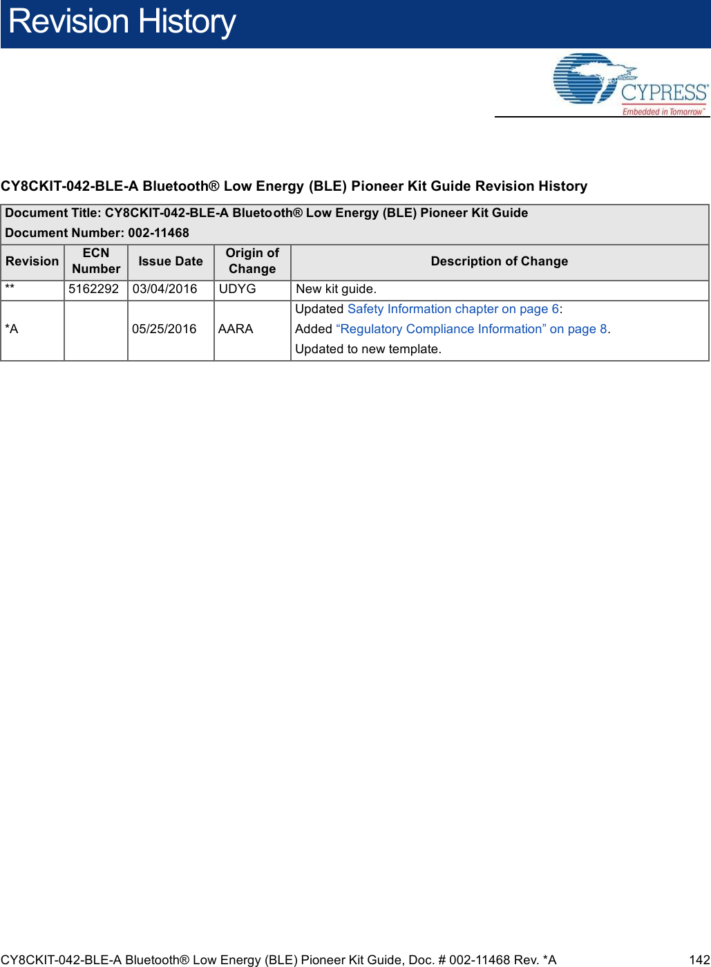
User manual3
Navigation menu
Upload a User Manual
Namespaces
Wiki Guide
HTML
PDF
Info
Views
User Manual
Discussion / Help
Navigation
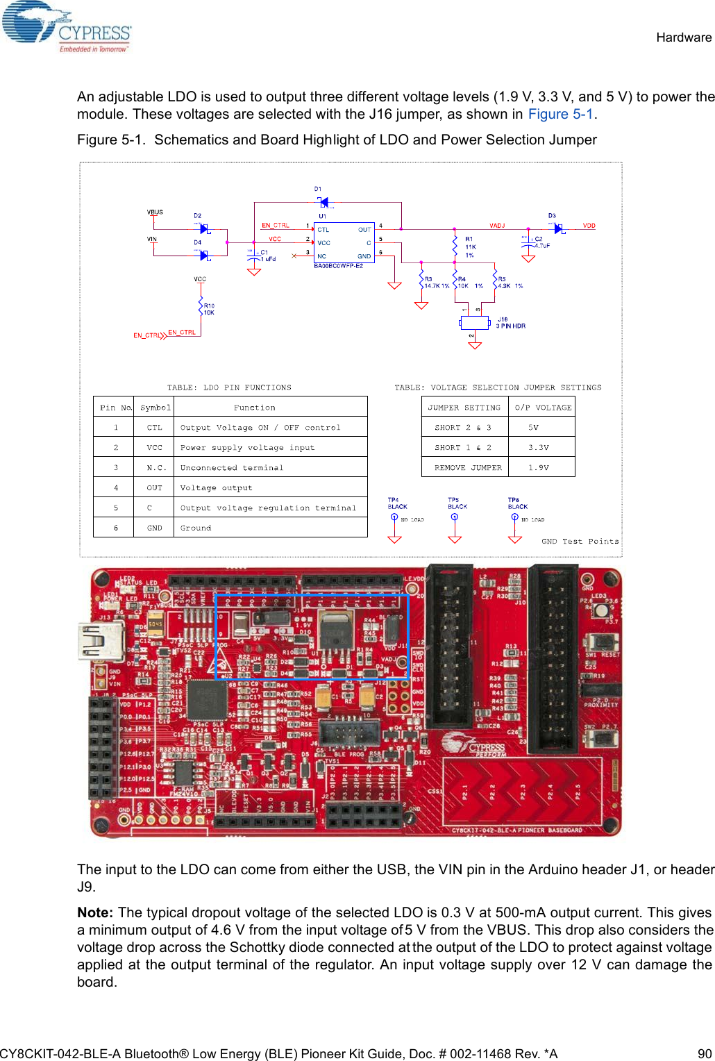
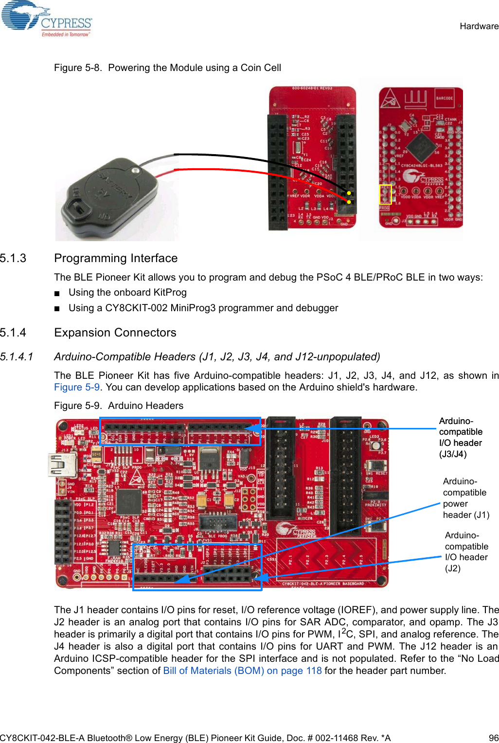
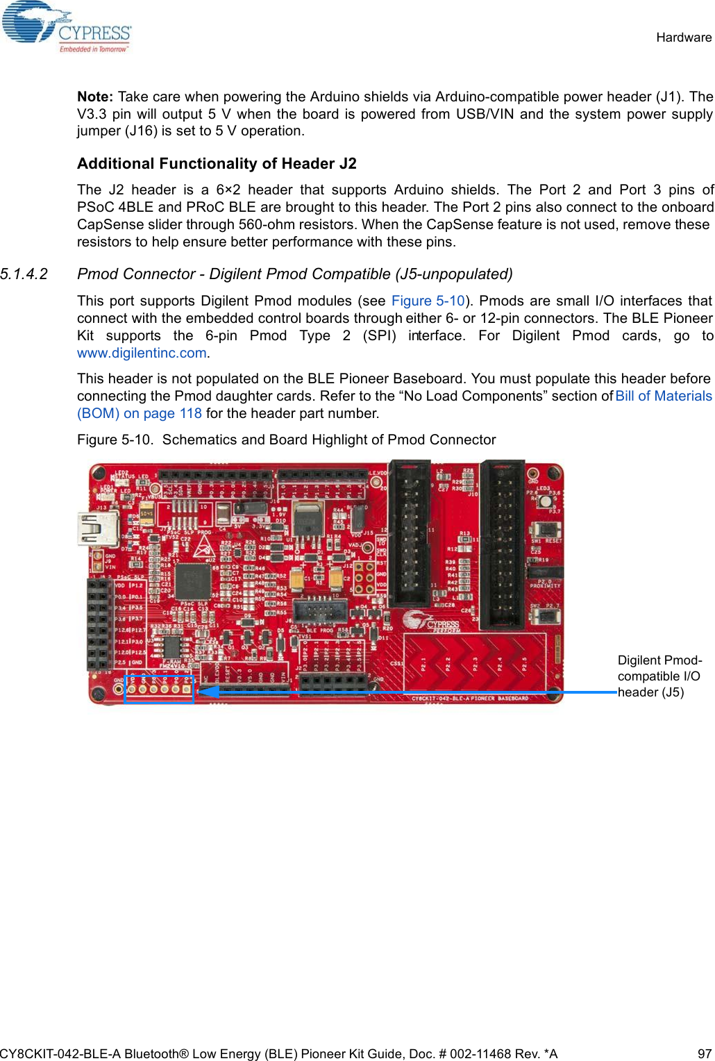
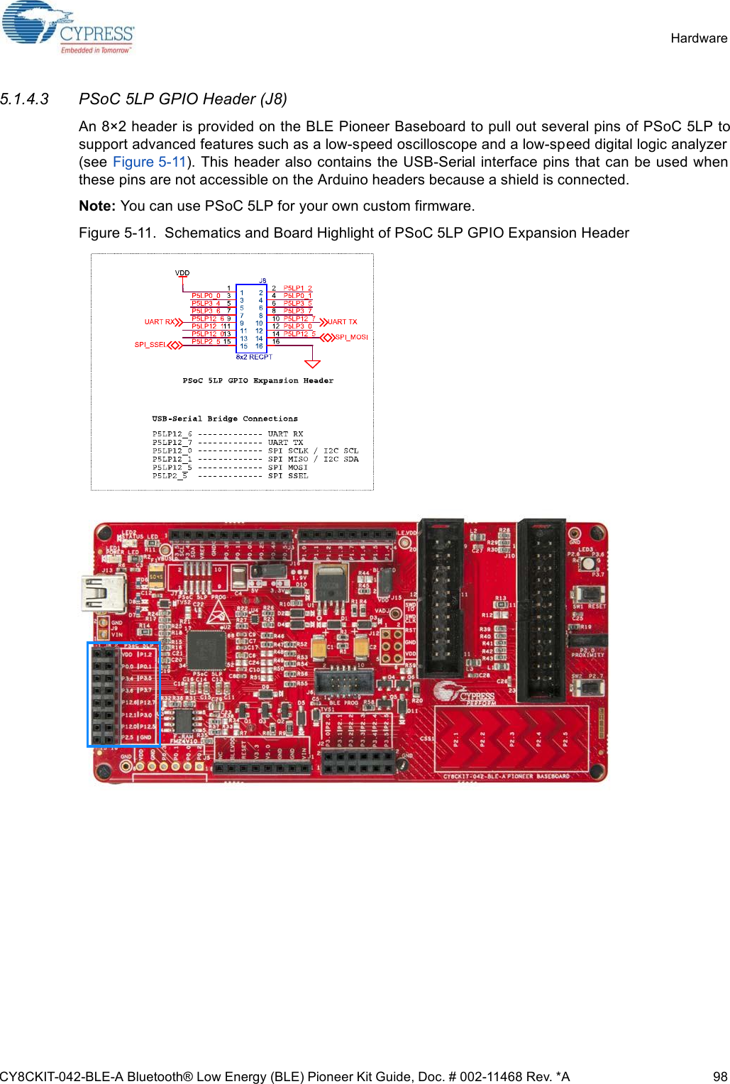
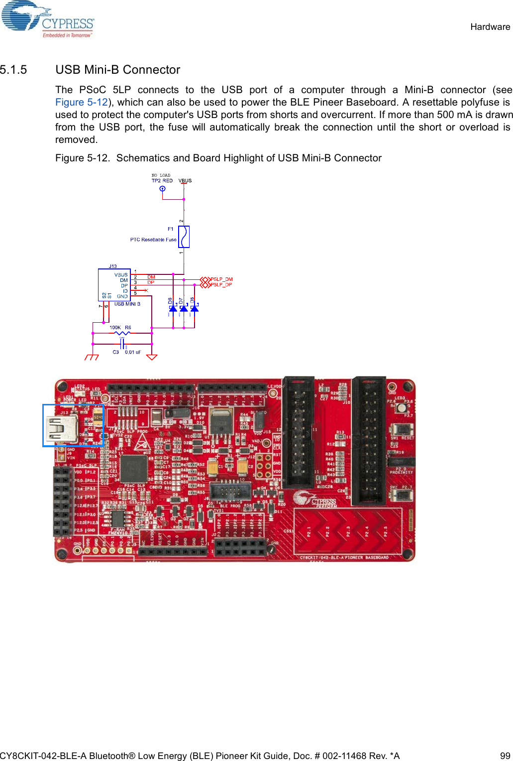
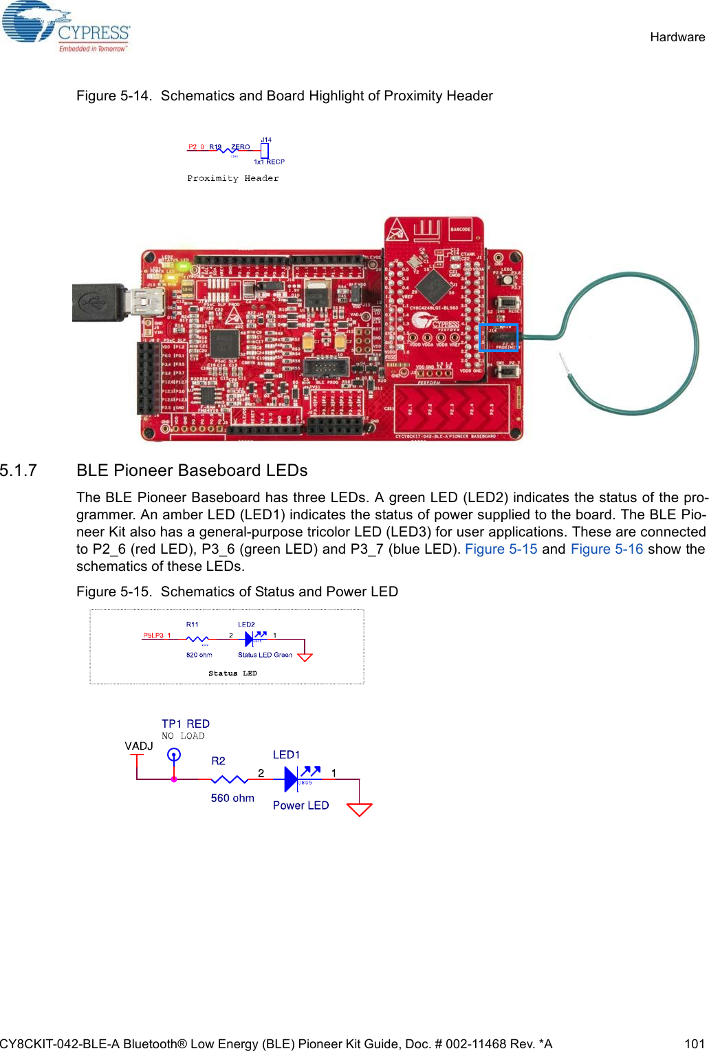
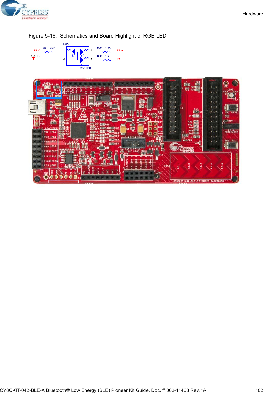
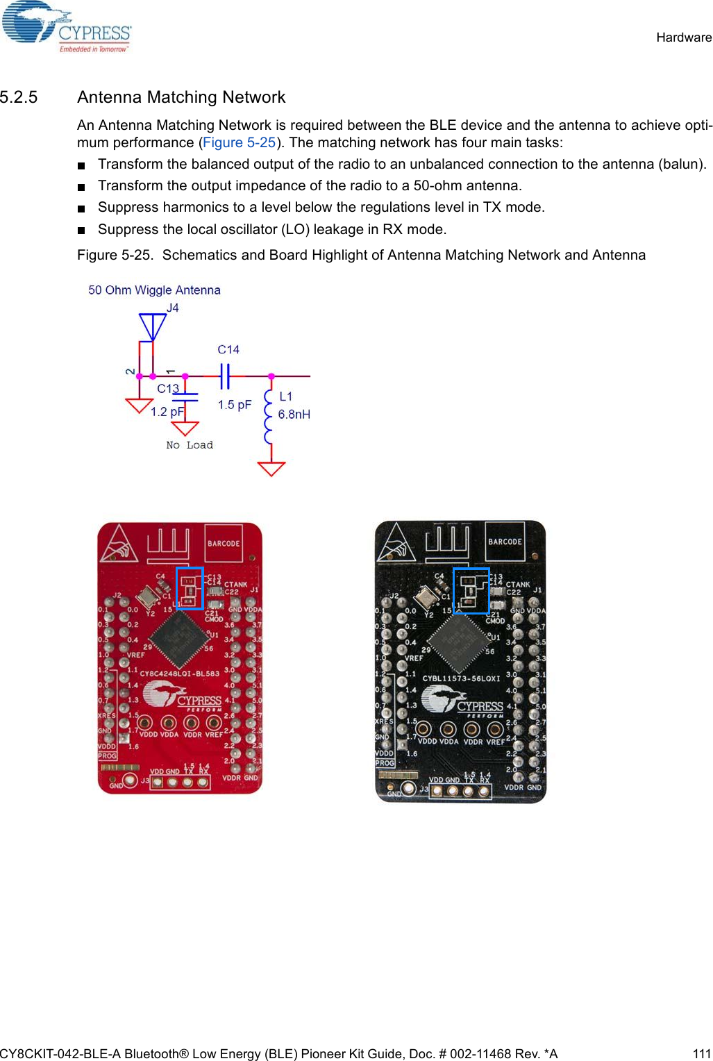
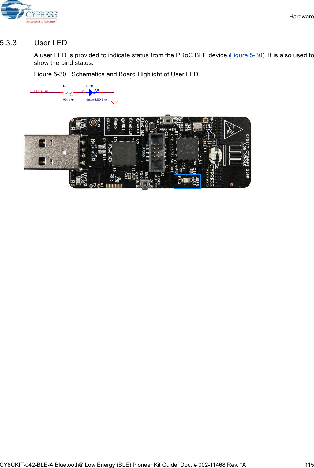
![CY8CKIT-042-BLE-A Bluetooth® Low Energy (BLE) Pioneer Kit Guide, Doc. # 002-11468 Rev. *A 100Hardware5.1.6 CapSense Circuit5.1.6.1 CapSense SliderThe BLE Pioneer Kit has a five-segment linear capacitive touch slider, which is connected to thePSoC 4 BLE/PRoC BLE Module pins (see Figure 5-13). The CMOD and CTANK capacitors arerequired for CapSense functionality and are provided on the modules (see Module Board onpage 107). A 2.2-nF capacitor is present on the CMOD pin, P4[0], for CapSense operation. BLEPioneer Kit also supports CapSense designs that enable waterproofing. The connection of the shieldto the pin or to ground is made by resistors R12 and R13, respectively. By default, R13 is mountedon the BLE Pioneer Baseboard, which connects the shield to ground. Populate R12 and remove R13when evaluating waterproofing designs, which will connect the shield to the designated pin, P1[6].Figure 5-13. Schematics and Board Highlight of CapSense Slider and Shield Setting5.1.6.2 Proximity HeaderThe BLE Pioneer Baseboard contains a header (J14) for CapSense proximity wire connection (seeFigure 5-14).](https://usermanual.wiki/Cypress-Semiconductor/CY5676A.User-manual3/User-Guide-3047712-Page-12.png)
![CY8CKIT-042-BLE-A Bluetooth® Low Energy (BLE) Pioneer Kit Guide, Doc. # 002-11468 Rev. *A 103Hardware5.1.8 Push-ButtonsThe BLE Pioneer Baseboard contains a reset push-button and a user push-button, as shown inFigure 5-17. The reset button is connected to the XRES pin of BLE device and is used to reset it.The user button is connected to P2[7] of the BLE device. Both the buttons connect to ground on acti-vation (active low).Figure 5-17. Schematics and Board Highlight of Reset Button and User ButtonRESET (SW1)User Button (SW2)](https://usermanual.wiki/Cypress-Semiconductor/CY5676A.User-manual3/User-Guide-3047712-Page-15.png)
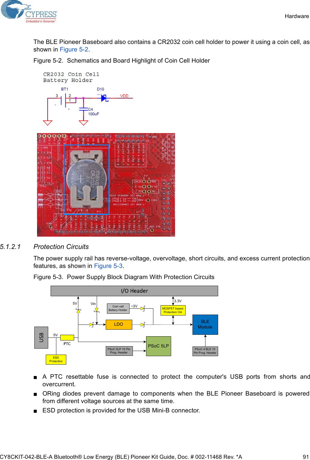
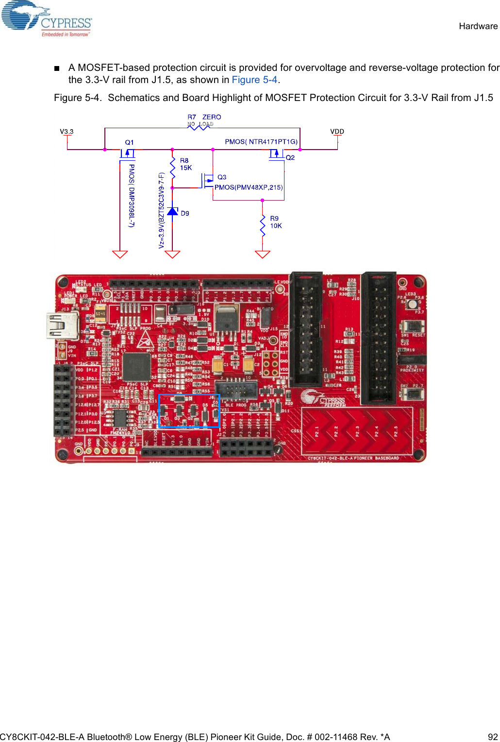
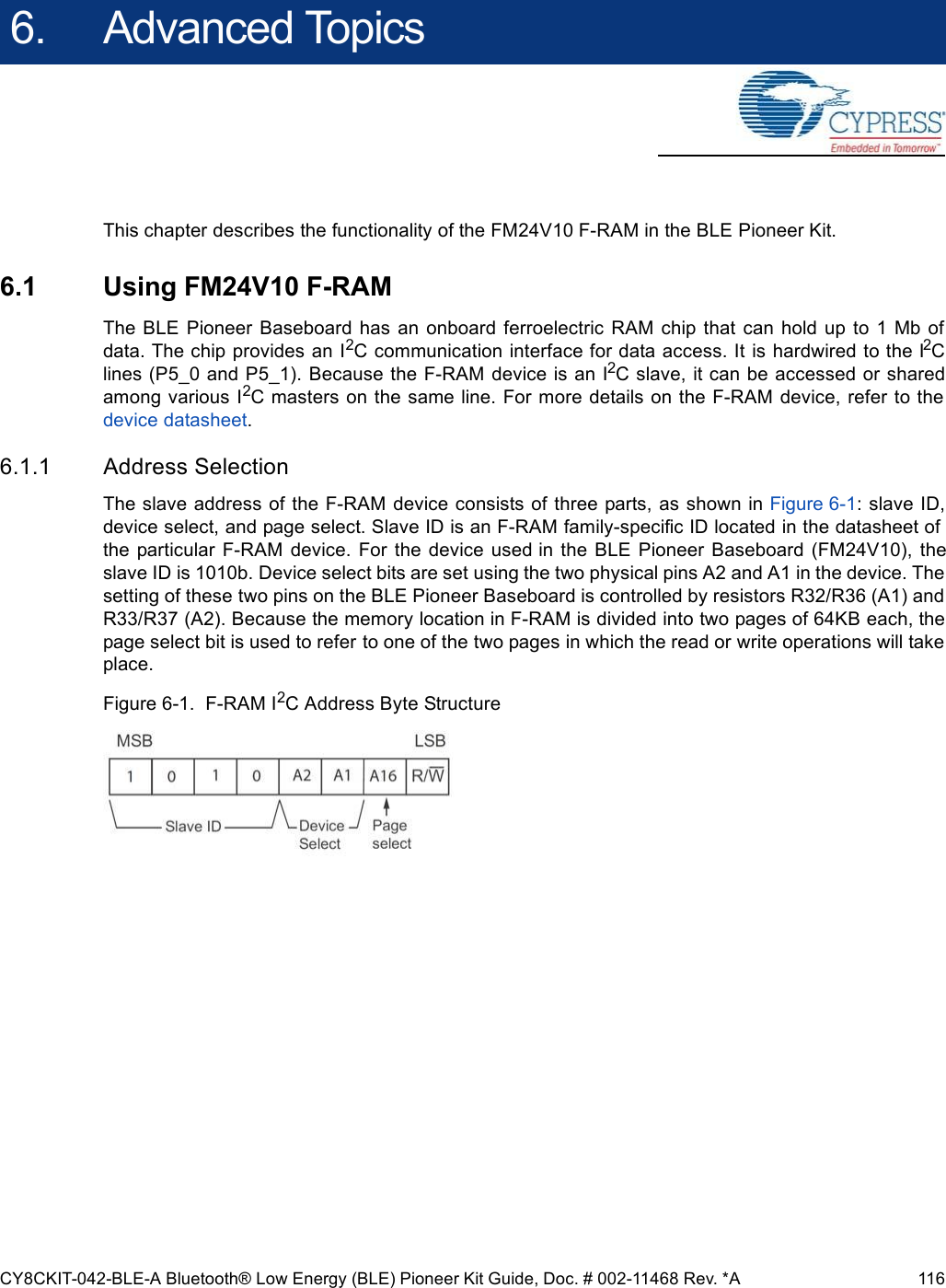
![CY8CKIT-042-BLE-A Bluetooth® Low Energy (BLE) Pioneer Kit Guide, Doc. # 002-11468 Rev. *A 104Hardware5.1.9 Cypress Ferroelectric RAM (F-RAM)The BLE Pioneer Baseboard contains the FM24V10-G F-RAM device (see Figure 5-18), which canbe accessed through I2C lines P5[0] and P5[1] of the PSoC 4 BLE/PRoC BLE Module. The F-RAM is1-Mbit (128KB) with an I2C speed up to 1 Mbps. The I2C slave address of the F-RAM device isseven bits wide, and the LSB two bits are configurable through physical pins and are hardwired to 00on the board. By default, the address of the F-RAM device used on the BLE Pioneer Baseboard is0x50. This address can be modified by changing the R32/R36 and R33/R37 pairs. The operatingvoltage range of the F-RAM is between 2 V and 3.6 V. To prevent the application of 5 V from theadjustable LDO regulator on the BLE Pioneer Baseboard, a MOSFET-based protection circuit similarto the one used for the 3.3-V rail is connected between the output of the regulator and the VDD pinof the F-RAM. The protection circuit cuts off the power to the F-RAM when the output of the regulatoris greater than 3.6 V.Figure 5-18. Schematics and Board Highlight of F-RAM](https://usermanual.wiki/Cypress-Semiconductor/CY5676A.User-manual3/User-Guide-3047712-Page-16.png)
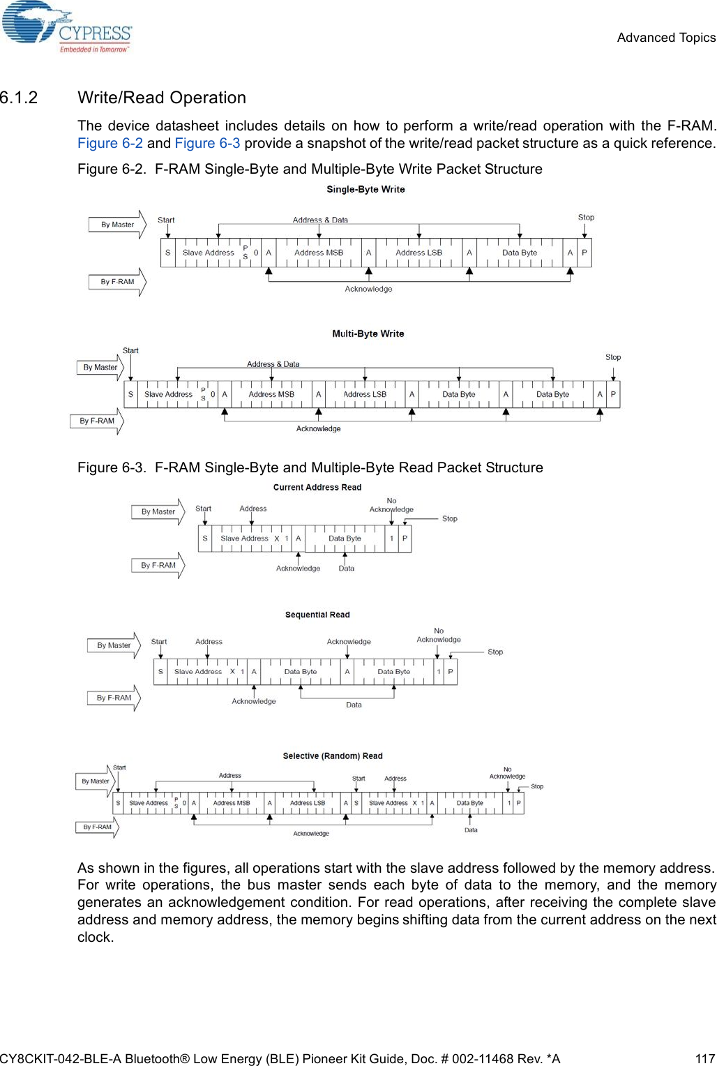

![CY8CKIT-042-BLE-A Bluetooth® Low Energy (BLE) Pioneer Kit Guide, Doc. # 002-11468 Rev. *A 129A.4 Programming BLE Modules via MiniProg3If the BLE Modules are to be used without the BLE Pioneer Baseboard, they can be programmedusing MiniProg3. The J2 header has five adjacent pins – VDDD, GND, XRES, P0[7], and P0[6].These pins can be used to program the BLE Module using MiniProg3.Figure A-2. Programming a BLE Module via MiniProg3Follow these steps to program the module:1. Connect the MiniProg3 to the J2 connector, with the VDD of the MiniProg3 aligned to the VDDD on the module.2. Click Start > All Programs > Cypress > PSoC Programmer <version> > PSoC Programmer <version>.3. Open the desired .hex file in PSoC Programmer.4. On the Programmer tab, set the Programming Mode to Reset.5. Set AutoDetection to On.6. Set Programmer Characteristics > Protocol to SWD.7. Set Programmer Characteristics > Voltage to the desired value.8. Click the Toggle Power icon below the menu bar to power the module.9. Click the Program icon below the menu bar to program the module.](https://usermanual.wiki/Cypress-Semiconductor/CY5676A.User-manual3/User-Guide-3047712-Page-41.png)
![CY8CKIT-042-BLE-A Bluetooth® Low Energy (BLE) Pioneer Kit Guide, Doc. # 002-11468 Rev. *A 137A.6.1 Arduino Uno-Compatible HeadersJ1 Arduino-Compatible Header Pin MapPin # Arduino PinPioneer Series KitsCY8CKIT-042 CY8CKIT-040 CY8CKIT-042-BLE CY8CKIT-044 CY8CKIT-0461 VIN VIN VIN VIN VIN VIN2 GND GND GND GND GND GND3 GND GND GND GND GND GND4 5V V5.0 V5.0 V5.0 V5.0 V5.05 3.3V V3.3 V3.3 V3.3 V3.3 V3.36 RESET RESET RESET RESET RESET RESET7 IOREF P4.VDD P4.VDD BLE.VDD P4.VDD P4L.VDD8 NC NC NC NC NC NCJ2 Arduino-Compatible Header Pin MapPin # Arduino PinPioneer Series KitsCY8CKIT-042 CY8CKIT-040 CY8CKIT-042-BLE CY8CKIT-044 CY8CKIT-0461 A0 P2[0] P0[0] P3[0] P2[0] P2[0]2 – P0[2]aa. These pins are also used for onboard peripherals. See the tables in “Onboard Peripherals” on page 140 for connection details.– P2[0] P2[6]aP3[6]a3 A1 P2[1] P0[1] P3[1] P2[1] P2[1]4 –- P0[3]a–P2[1]aP6[5]aP3[7]a5 A2 P2[2] P0[2]aP3[2] P2[2] P2[2]6 – P4_VDD – P2[2]aP0[6]aP9[0]7 A3 P2[3] P0[4]aP3[3] P2[3] P2[3]8 – P1[5]a–P2[3]aP4[4]aP9[1]9 A4 P2[4] P1[3] P3[4] P2[4] P2[4]10 – P1[4]a–P2[4]aP4[5]aP9[2]11 A5 P2[5] P1[2] P3[5] P2[5] P2[5]12 – P1[3]a–P2[5]aP4[6]aP9[3]13 – P0[0] – – P0[0] –14 – GND – – GND –15 – P0[1] – – P0[1] –16 – P1[2]a– – P3[4]a–17 – P1[0] – – P0[7]a–18 – P1[1]a– – P3[5]a–](https://usermanual.wiki/Cypress-Semiconductor/CY5676A.User-manual3/User-Guide-3047712-Page-49.png)
![CY8CKIT-042-BLE-A Bluetooth® Low Energy (BLE) Pioneer Kit Guide, Doc. # 002-11468 Rev. *A 138J3 Arduino-Compatible Header Pin Map#Arduino PinPioneer Series KitsCY8CKIT-042 CY8CKIT-040 CY8CKIT-042-BLE CY8CKIT-044 CY8CKIT-0461 D8 P2[6] P1[4] P0[5] P0[2] P0[2]2 - - - - - P3[4]3 D9 P3[6] P1[5] P0[4] P0[3] P0[3]4 - - - - - P6[5]5 D10 P3[4] P1[6] P0[2] P2[7] P6[3]6 - - - - - P6[3]7 D11 P3[0] P1[1]aa. These pins are also used for onboard peripheral connections. Refer to the A.6.2 Onboard Peripherals section for connection details.P0[0] P6[0] P6[0]8 - - - - - P6[0]9 D12 P3[1] P3[1] P0[1] P6[1] P6[1]10 - - - - - P6[1]11 D13 P0[6] P1[7] P0[3] P6[2] P6[2]12 - - - - - P6[2]13 GND GND GND GND GND GND14 - - - - - GND15 AREF P1[7] NC VREF P1[7] VREF16 - - - - - VREF17 SDA P4[1] P1[3] P3[4] P4[1] P4[1]18 - - - - - P4[1]19 SCL P4[0] P1[2] P3[5] P4[0] P4[0]20 - - - - - P4[0]](https://usermanual.wiki/Cypress-Semiconductor/CY5676A.User-manual3/User-Guide-3047712-Page-50.png)
![CY8CKIT-042-BLE-A Bluetooth® Low Energy (BLE) Pioneer Kit Guide, Doc. # 002-11468 Rev. *A 139J4 Arduino-Compatible Header Pin Map#Arduino PinPioneer Series KitsCY8CKIT-042 CY8CKIT-040 CY8CKIT-042-BLE CY8CKIT-044 CY8CKIT-0461 D0 P0[4] P0[5] P1[4] P3[0] P3[0]2 - - - - - P8[0]3 D1 P0[5] P0[6] P1[5] P3[1] P3[1]4 - - - - - P8[1]5 D2 P0[7]aa. These pins are also used for onboard peripheral connections. Refer to the A.6.2 Onboard Peripherals section for connection details.P0[7] P1[6] P1[0] P1[0]6 - - - - - P8[2]7 D3 P3[7] P3[2]aP1[7] P1[1] P1[1]8 - - - - - P8[3]9 D4 P0[0] P0[3] P1[3] P1[2] P1[2]10 - - - - - P8[4]11 D5 P3[5] P3[0] P1[2] P1[3] P1[3]12 - - - - - P8[5]13 D6 P1[0] P1[0] P1[1] P5[3] P5[6]14 - - - - - P8[6]15 D7 P2[7] P2[0]aP1[0] P5[5] P5[5]16 - - - - - P8[7]](https://usermanual.wiki/Cypress-Semiconductor/CY5676A.User-manual3/User-Guide-3047712-Page-51.png)
![CY8CKIT-042-BLE-A Bluetooth® Low Energy (BLE) Pioneer Kit Guide, Doc. # 002-11468 Rev. *A 140A.6.2 Onboard Peripherals#CapSense PinPioneer Series KitsCY8CKIT-042 (Linear Slider) CY8CKIT-040 CY8CKIT-042-BLE (Linear Slider)CY8CKIT-044 (Gesture Pad)CY8CKIT-046 (Gesture Pad with Radial Slider)aa. The CapSense elements are present on the CY8CKIT-046 shield board. The radial slider (CapSense sensors 6 to 13) is symmetric and thesensor order can be shifted to fit your requirement, that is, the desired zero position on the slider.1CapSense Sensor 1P1[1]/CS_LS_E0 – P2[1]/CS_LS_E0 P4[4]/CS_GES_CRP0[6]/CS_GES_CR2CapSense Sensor 2P1[2]/CS_LS_E1 – P2[2]/CS_LS_E1 P4[5]/CS_GES_UPP4[5]/CS_GES_LT3CapSense Sensor 3P1[3]/CS_LS_E2 – P2[3]/CS_LS_E2 P4[6]/CS_GES_LTP4[4]/CS_GES_UP4CapSense Sensor 4P1[4]/CS_LS_E3 – P2[4]/CS_LS_E3 P3[4]/CS_GES_DNP4[7]/CS_GES_RT5CapSense Sensor 5P1[5]/CS_LS_E4 – P2[5]/CS_LS_E4 P3[5]/CS_GES_RTP4[6]/CS_GES_DN6CapSense Sensor 10 – – – – P7[4]/CS_RS_E07CapSense Sensor 11 – – – – P7[5]/CS_RS_E18CapSense Sensor 12 – – – – P7[6]/CS_RS_E29CapSense Sensor 13 – – – – P7[7]/CS_RS_E310 CapSense Sensor 6 – – – – P0[0]/CS_RS_E411 CapSense Sensor 7 – – – – P0[1]/CS_RS_E512 CapSense Sensor 8 – – – – P7[2]/CS_RS_E613 CapSense Sensor 9 – – – – P7[3]/CS_RS_E714 CMODbb. CMOD0, CTANK0, CMOD1, and CTANK1 are only present in the CY8CKIT-046 PSoC 4 L-Series Pioneer Kit.P4[2] P0[4] P4[0] P4[2] P4[2]15 CTANKbP4[3] P0[2] P4[1] P4[3] P4[3]16 CMODb– – – – P5[0]17 CTANKb– – – – P5[1]18 CapSense Shield P0[1] – P1[6] P0[1] P0[2]](https://usermanual.wiki/Cypress-Semiconductor/CY5676A.User-manual3/User-Guide-3047712-Page-52.png)
![CY8CKIT-042-BLE-A Bluetooth® Low Energy (BLE) Pioneer Kit Guide, Doc. # 002-11468 Rev. *A 141Proximity Header Pin MapPin # Description Pioneer Series KitsCY8CKIT-042 CY8CKIT-040 CY8CKIT-042-BLE CY8CKIT-044 CY8CKIT-0461PROXIMITY – P2[0] P2[0] P3[7] P9[4]2 – – – P3[6] P9[5]RGB LED Pin MapPin # Color Pioneer Series KitsCY8CKIT-042 CY8CKIT-040 CY8CKIT-042-BLE CY8CKIT-044 CY8CKIT-0461 Red P1[6] P3[2] P2[6] P0[6] P5[2]2 Green P0[2] P1[1] P3[6] P2[6] P5[3]3 Blue P0[3] P0[2] P3[7] P6[5] P5[4]User Switch Pin MapPin # Description Pioneer Series KitsCY8CKIT-042 CY8CKIT-040 CY8CKIT-042-BLE CY8CKIT-044 CY8CKIT-0461 SW2 P0[7] – P2[7] P0[7] P0[7]](https://usermanual.wiki/Cypress-Semiconductor/CY5676A.User-manual3/User-Guide-3047712-Page-53.png)