Cypress Semiconductor 0737 This product is a Bluetooth wireless EZ-BT WICED SIP Module User Manual CYW20737S 0514
Cypress Semiconductor This product is a Bluetooth wireless EZ-BT WICED SIP Module CYW20737S 0514
Contents
- 1. User Manual_CYW20732S - 0514
- 2. User Manual_CYW20736S - 0514
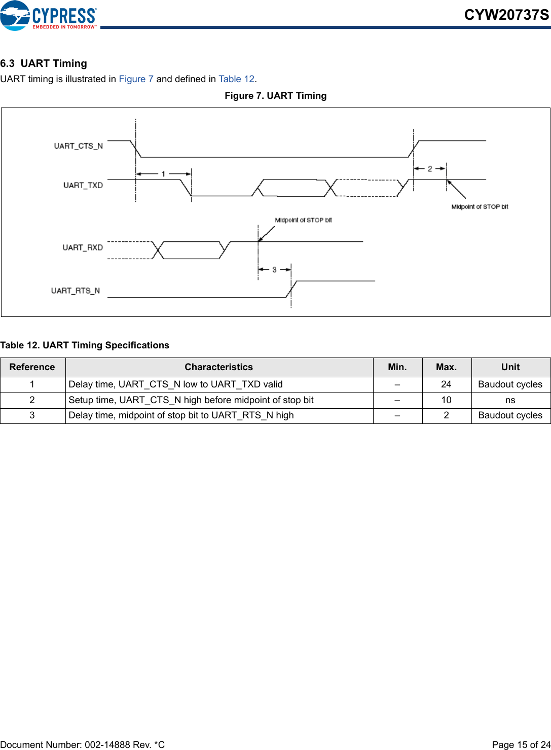
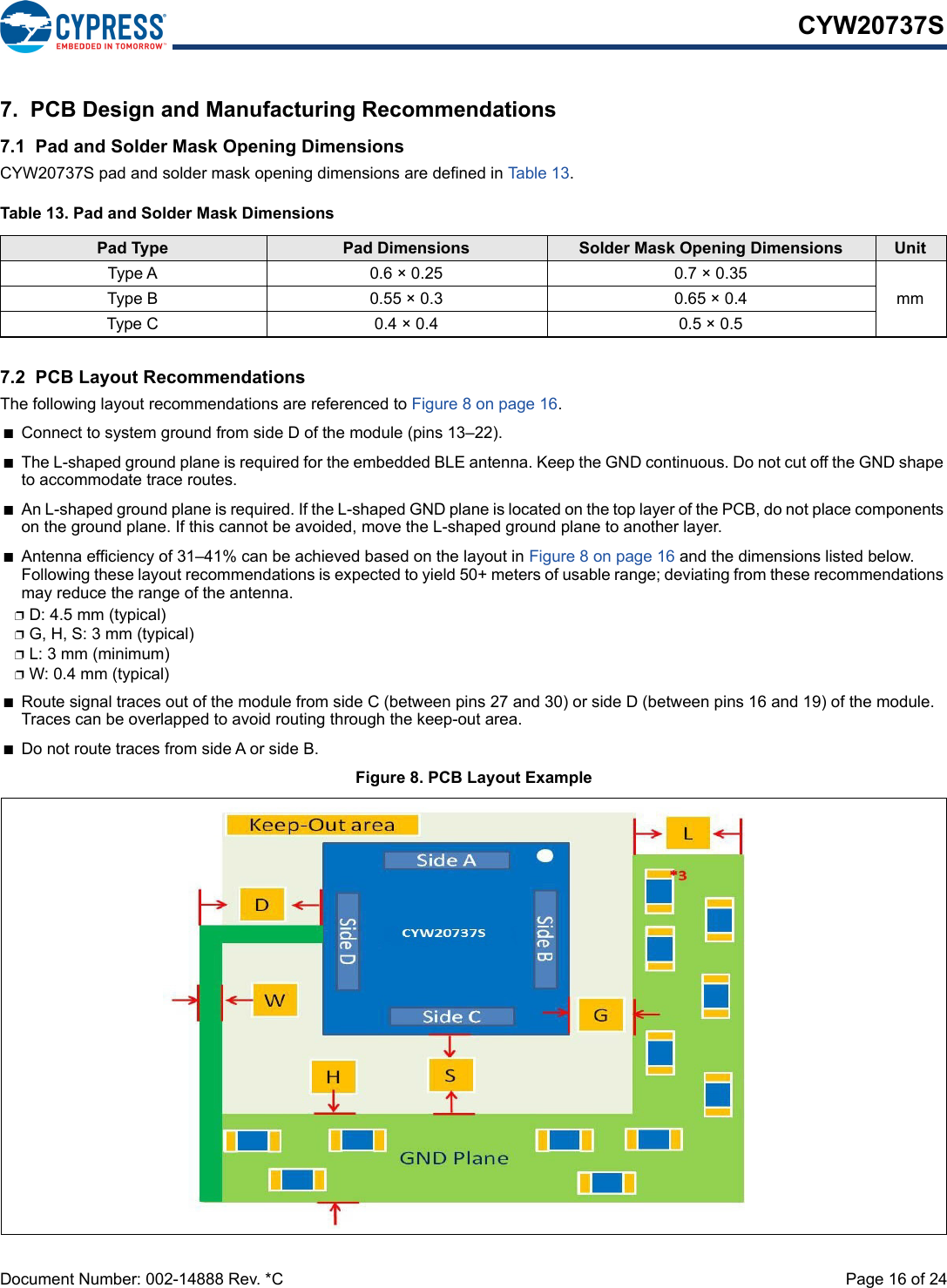
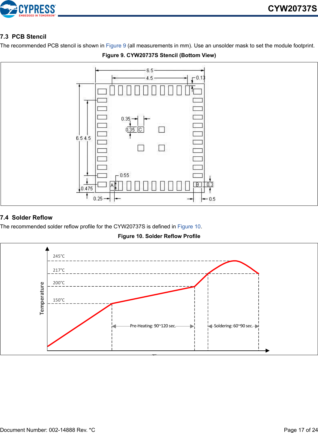
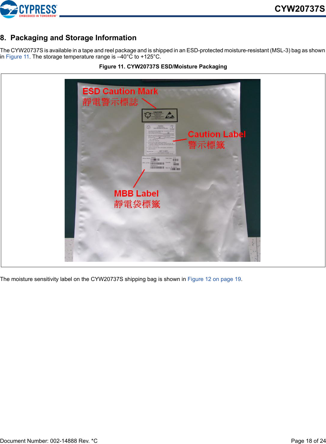
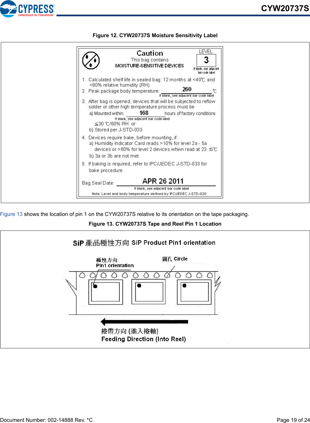
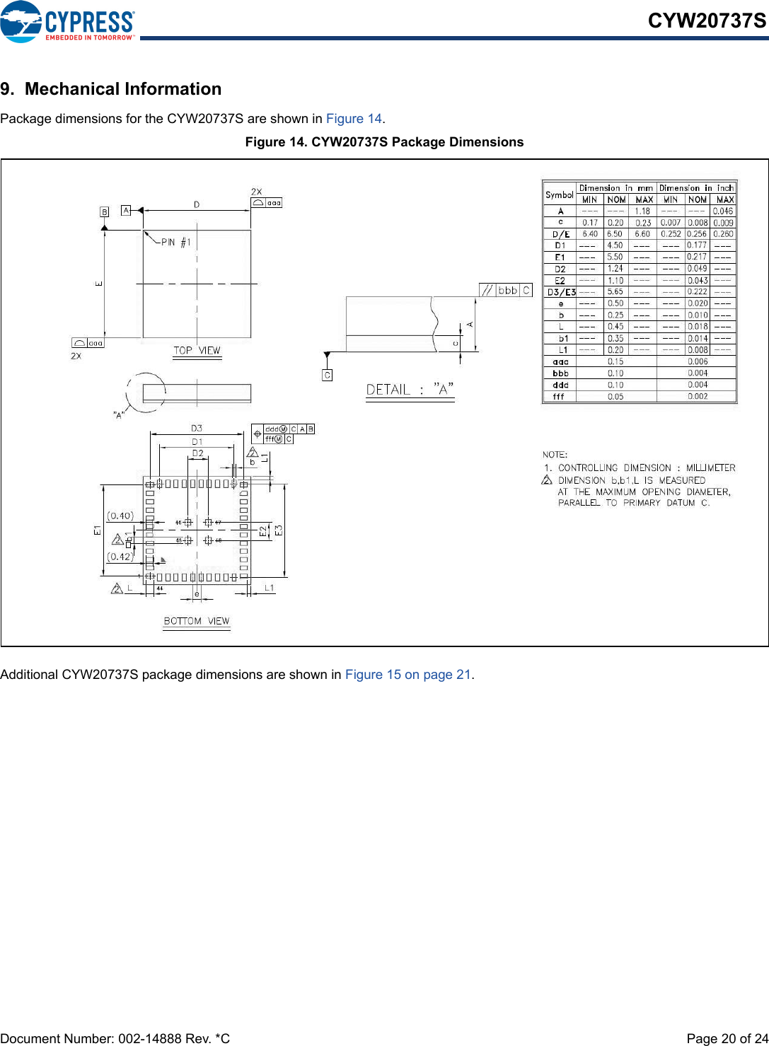
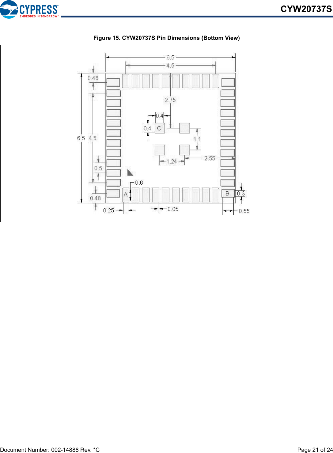
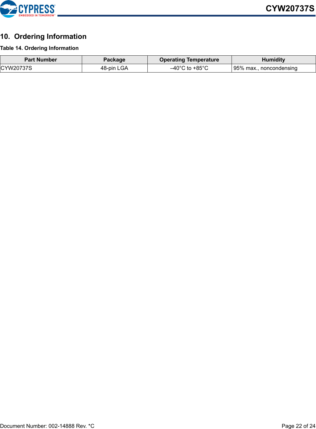
- 3. User Manual_CYW20737S - 0514
User Manual_CYW20737S - 0514
![PRELIMINARY'RFXPHQW1XPEHU5HY$ 3DJHRI5HJXODWRU\,QIRUPDWLRQ)&&)&&127,&(WKH)&&5XOHV7KHGHYLFHPHHWVWKHUHTXLUHPHQWVIRUPRGXODUWUDQVPLWWHUDSSURYDODVGHWDLOHGLQ)&&SXEOLF1RWLFH'$WUDQVPLWWHU2SHUDWLRQLVVXEMHFWWRWKHIROORZLQJWZRFRQGLWLRQV7KLVGHYLFHPD\QRWFDXVHKDUPIXOLQWHUIHUHQFHDQG7KLVGHYLFHPXVWDFFHSWDQ\LQWHUIHUHQFHUHFHLYHGLQFOXGLQJLQWHUIHUHQFHWKDWPD\FDXVHXQGHVLUHGRSHUDWLRQ&$87,217KH)&&UHTXLUHVWKHXVHUWREHQRWLILHGWKDWDQ\FKDQJHVRUPRGLILFDWLRQVPDGHWRWKLVGHYLFHWKDWDUHQRWH[SUHVVO\DSSURYHGE\&\SUHVV6HPLFRQGXFWRUPD\YRLGWKHXVHUVDXWKRULW\WRRSHUDWHWKHHTXLSPHQW7KLVHTXLSPHQWKDVEHHQWHVWHGDQGIRXQGWRFRPSO\ZLWKWKHOLPLWVIRUD&ODVV%GLJLWDOGHYLFHSXUVXDQWWR3DUWRIWKH)&&5XOHV7KHVHOLPLWVDUHGHVLJQHGWRSURYLGHUHDVRQDEOHSURWHFWLRQDJDLQVWKDUPIXOLQWHUIHUHQFHLQDUHVLGHQWLDOLQVWDOODWLRQ7KLVHTXLSPHQWJHQHUDWHVXVHVDQGFDQUDGLDWHUDGLRIUHTXHQF\HQHUJ\DQGLIQRWLQVWDOOHGDQGXVHGLQDFFRUGDQFHZLWKWKHLQVWUXFWLRQVrPD\FDXVHKDUPIXOLQWHUIHUHQFHWRUDGLRFRPPXQLFDWLRQV+RZHYHUWKHUHLVQRJXDUDQWHHWKDWLQWHUIHUHQFHZLOOQRWRFFXULQDSDUWLFXODULQVWDOODWLRQ,IWKLVHTXLSPHQWGRHVFDXVHKDUPIXOLQWHUIHUHQFHWRUDGLRRUWHOHYLVLRQUHFHSWLRQZKLFKFDQEHGHWHUPLQHGE\WXUQLQJWKHHTXLSPHQWRIIDQGRQWKHXVHULVHQFRXUDJHGWRWU\WRFRUUHFWWKHLQWHUIHUHQFHE\RQHRUPRUHRIWKHIROORZLQJPHDVXUHVn5HRULHQWRUUHORFDWHWKHUHFHLYLQJDQWHQQDn,QFUHDVHWKHVHSDUDWLRQEHWZHHQWKHHTXLSPHQWDQGUHFHLYHUn&RQQHFWWKHHTXLSPHQWLQWRDQRXWOHWRQDFLUFXLWGLIIHUHQWIURPWKDWWRZKLFKWKHUHFHLYHULVFRQQHFWHGn&RQVXOWWKHGHDOHURUDQH[SHULHQFHGUDGLR79WHFKQLFLDQIRUKHOS/$%(/,1*5(48,5(0(1767KH2ULJLQDO(TXLSPHQW0DQXIDFWXUHU2(0PXVWHQVXUHWKDW)&&ODEHOOLQJUHTXLUHPHQWVDUHPHW7KLVLQFOXGHVDFOHDUO\YLVLEOHODEHORQWKHRXWVLGHRIWKH2(0HQFORVXUHVSHFLI\LQJWKHDSSURSULDWH&\SUHVV6HPLFRQGXFWRU)&&LGHQWLILHUIRUWKLVSURGXFWDVZHOODVWKH)&&1RWLFHDERYH7KH)&&LGHQWLILHULV)&&,',QDQ\FDVHWKHHQGSURGXFWPXVWEHODEHOHGH[WHULRUZLWK&RQWDLQV)&&,' $17(11$:$51,1*7KLVGHYLFHLVWHVWHGZLWKDVWDQGDUG60$FRQQHFWRUDQGZLWKWKHDQWHQQDVOLVWHGEHORZ:KHQLQWHJUDWHGLQWKH2(0VSURGXFWWKHVHIL[HGDQWHQQDVUHTXLUHLQVWDOODWLRQSUHYHQWLQJHQGXVHUVIURPUHSODFLQJWKHPZLWKQRQDSSURYHGDQWHQQDV$Q\DQWHQQDQRWLQWKHIROORZLQJWDEOHPXVWEHWHVWHGWRFRPSO\ZLWK)&&6HFWLRQIRUXQLTXHDQWHQQDFRQQHFWRUVDQG6HFWLRQIRUHPLVVLRQV5)(;32685(7RFRPSO\ZLWK)&&5)([SRVXUHUHTXLUHPHQWVWKH2ULJLQDO(TXLSPHQW0DQXIDFWXUHU2(0PXVWHQVXUHWRLQVWDOOWKHDSSURYHGDQWHQQDLQWKHSUHYLRXV7KHSUHFHGLQJVWDWHPHQWPXVWEHLQFOXGHGDVD&$87,21VWDWHPHQWLQPDQXDOVIRUSURGXFWVRSHUDWLQJZLWKWKHDSSURYHGDQWHQQDVLQ7DEOHRQSDJHWRDOHUWXVHUVRQ)&&5)([SRVXUHFRPSOLDQFH$Q\QRWLILFDWLRQWRWKHHQGXVHURILQVWDOODWLRQRUUHPRYDOLQVWUXFWLRQVDERXWWKHLQWHJUDWHGUDGLRPRGXOHLVQRWDOORZHG7KHUDGLDWHGRXWSXWSRZHURI DQWHQQD)&&,' LVIDUEHORZWKH)&&UDGLRIUHTXHQF\H[SRVXUHOLPLWV1HYHUWKHOHVVXVH VXFKDPDQQHUWKDWPLQLPL]HVWKHSRWHQWLDOIRUKXPDQFRQWDFWGXULQJQRUPDORSHUDWLRQ(QGXVHUVPD\ QRW EHSURYLGHG ZLWKWKH PRGXOH LQVWDOODWLRQLQVWUXFWLRQV 2(0LQWHJUDWRUVDQGHQG XVHUV PXVW EHSURYLGHGZLWKWUDQVPLWWHURSHUDWLQJFRQGLWLRQVIRUVDWLVI\LQJ5)H[SRVXUHFRPSOLDQFHThe device complies with part 15 ofWAP-0737WAP-0737the device with the PCB WAP-0737the device](https://usermanual.wiki/Cypress-Semiconductor/0737.User-Manual-CYW20737S-0514/User-Guide-3848777-Page-23.png)
![PRELIMINARY &<%7&HUWLILFDWLRQLVOLFHQVHGWRPHHWWKHUHJXODWRU\U HTXLUHPHQWVRI,QGXVWU\&DQDGD,&/LFHQVH,&0DQXIDFWXUHUVRIPRELOHIL[HGRUSRUWDEOHGHYLFHVLQFRUSRUDWLQJWKLVPRGXOHDUHDGYLVHGWRFODULI\DQ\UHJXODWRU\TXHVWLRQVDQGHQVXUHFRPSOLDQFH IRU 6$5 DQGRU 5) H[SRVXUH OLPLWV 8VHUV FDQ REWDLQ &DQDGLDQ LQIRUPDWLRQ RQ 5) H[SRVXUH DQG FRPSOLDQFH IURPZZZLFJFFD7KLVGHYLFHKDVEHHQGHVLJQHGWRRSHUDWHZLWKWKHDQWHQQDVOLVWHGLQ7DEOHRQSDJHKDYLQJDPD[LPXPJDLQRI QQDVQRWLQFOXGHGLQWKLVOLVWRUKDYLQJDJDLQJUHDWHU G%LDUHVWULFWO\SURKLELWHGIRUXVHZLWKWKLVGHYLFH7KHUHTXLUHGDQWHQQDLPSHGDQFHLVRKPV7KHDQWHQQDXVHGIRUWKLVWUDQVPLWWHUPXVWQRWEHFRORFDWHGRURSHUDWLQJLQFRQMXQFWLRQZLWKDQ\RWKHUDQWHQQDRUWUDQVPLWWHU,&127,&(7KH GHYLFHLQFOXGLQJ WKH EXLOWLQ WUDFH DQWHQQD FRPSOLHV ZLWK &DQDGD 566*(1 5XOHV 7KHGHYLFH PHHWV WKHUHTXLUHPHQWVIRUPRGXODUWUDQVPLWWHUDSSURYDODVGHWDLOHGLQ566*(12SHUDWLRQLVVXEMHFWWRWKHIROORZLQJWZRFRQGLWLRQV7KLVGHYLFHPD\QRWFDXVHKDUPIXOLQWHUIHUHQFHDQG7KLVGHYLFHPXVWDFFHSWDQ\LQWHUIHUHQFHUHFHLYHGLQFOXGLQJLQWHUIHUHQFHWKDWPD\FDXVHXQGHVLUHGRSHUDWLRQ,&5$',$7,21(;32685(67$7(0(17)25&$1$'$7KLVGHYLFHFRPSOLHVZLWK,QGXVWU\&DQDGDOLFHQFHH[HPSW566VWDQGDUGV2SHUDWLRQLVVXEMHFWWRWKHIROORZLQJWZRFRQGLWLRQVWKLVGHYLFH PD\ QRW FDXVHLQWHUIHUHQFHDQG WKLV GHYLFH PXVWDFFHSWDQ\LQWHUIHUHQFHLQFOXGLQJ LQWHUIHUHQFH WKDW PD\FDXVHXQGHVLUHGRSHUDWLRQRIWKHGHYLFH/HSUpVHQWDSSDUHLOHVWFRQIRUPHDX[&15G,QGXVWULH&DQDGDDSSOLFDEOHVDX[DSSDUHLOVUDGLRH[HPSWVGHOLFHQFH/H[SORLWDWLRQHVWDXWRULVpHDX[GHX[FRQGLWLRQVVXLYDQWHVODSSDUHLOQHGRLWSDVSURGXLUHGHEURXLOODJHHWOXWLOLVDWHXUGHODSSDUHLOGRLWDFFHSWHUWRXWEURXLOODJHUDGLRpOHFWULTXHVXELPrPHVLOHEURXLOODJHHVWVXVFHSWLEOHGHQFRPSURPHWWUHOHIRQFWLRQQHPHQW/$%(/,1*5(48,5(0(1767KH2ULJLQDO(TXLSPHQW0DQXIDFWXUHU2(0PXVWHQVXUHWKDW,&ODEHOOLQJUHTXLUHPHQWVDUHPHW7KLVLQFOXGHVDFOHDUO\YLVLEOHODEHORQWKHRXWVLGHRIWKH2(0HQFORVXUHVSHFLI\LQJWKHDSSURSULDWH&\SUHVV6HPLFRQGXFWRU,&LGHQWLILHUIRUWKLVSURGXFWDVZHOODVWKH,&1RWLFHDERYH7KH,&LGHQWLILHULV ,QDQ\FDVHWKHHQGSURGXFWPXVWEHODEHOHGLQL WVH[WHULRUZLWK&RQWDLQV,&(XURSHDQ577('HFODUDWLRQRI&RQIRUPLW\+HUHE\&\SUHVV6HPLFRQGXFWRUGHFODUHVWKDWWKH%OXHWRRWKPRGXOHFRPSOLHVZLWKWKHHVVHQWLDOUHTXLUHPHQWVDQGRWKHUUHOHYDQWSURYLVLRQVRI'LUHFWLYH(&$VDUHVXOWRIWKHFRQIRUPLW\DVVHVVPHQWSURFHGXUHGHVFULEHGLQ$QQH[,,,RIWKH'LUHFWLYH(&WKHHQGFXVWRPHUHTXLSPHQWVKRXOGEHODEHOHGDVIROORZV$OOYHUVLRQVRIWKH UHIHUHQFHGHVLJQFDQEHXVHGLQWKHIROORZLQJFRXQWULHV$XVWULD%HOJLXP&\SUXV&]HFK5HSXEOLF'HQPDUN(VWRQLD)LQODQG)UDQFH*HUPDQ\*UHHFH+XQJDU\,UHODQG,WDO\/DWYLD/LWKXDQLD/X[HPERXUJ0DOWD3RODQG3RUWXJDO6ORYDNLD6ORYHQLD6SDLQ6ZHGHQ7KH1HWKHUODQGVWKH8QLWHG.LQJGRP6ZLW]HUODQGDQG1RUZD\ISEDThe device7922A-0737-1.5dBi, antethan -1.5(3) No SAR evaluation is required since maximum transmitter Pout is below IC threshold(3) Aucune évaluation SAR n'est requise étant donné que la puissance maximale de l'émetteur est inférieure au seuil IC.7922A-07377922A-0737device in the specified](https://usermanual.wiki/Cypress-Semiconductor/0737.User-Manual-CYW20737S-0514/User-Guide-3848777-Page-24.png)