Cypress Semiconductor 0737 This product is a Bluetooth wireless EZ-BT WICED SIP Module User Manual CYW20732S Bluetooth Low Energy SiP Module
Cypress Semiconductor This product is a Bluetooth wireless EZ-BT WICED SIP Module CYW20732S Bluetooth Low Energy SiP Module
Contents
- 1. User Manual_CYW20732S - 0514
- 2. User Manual_CYW20736S - 0514
- 3. User Manual_CYW20737S - 0514
User Manual_CYW20732S - 0514
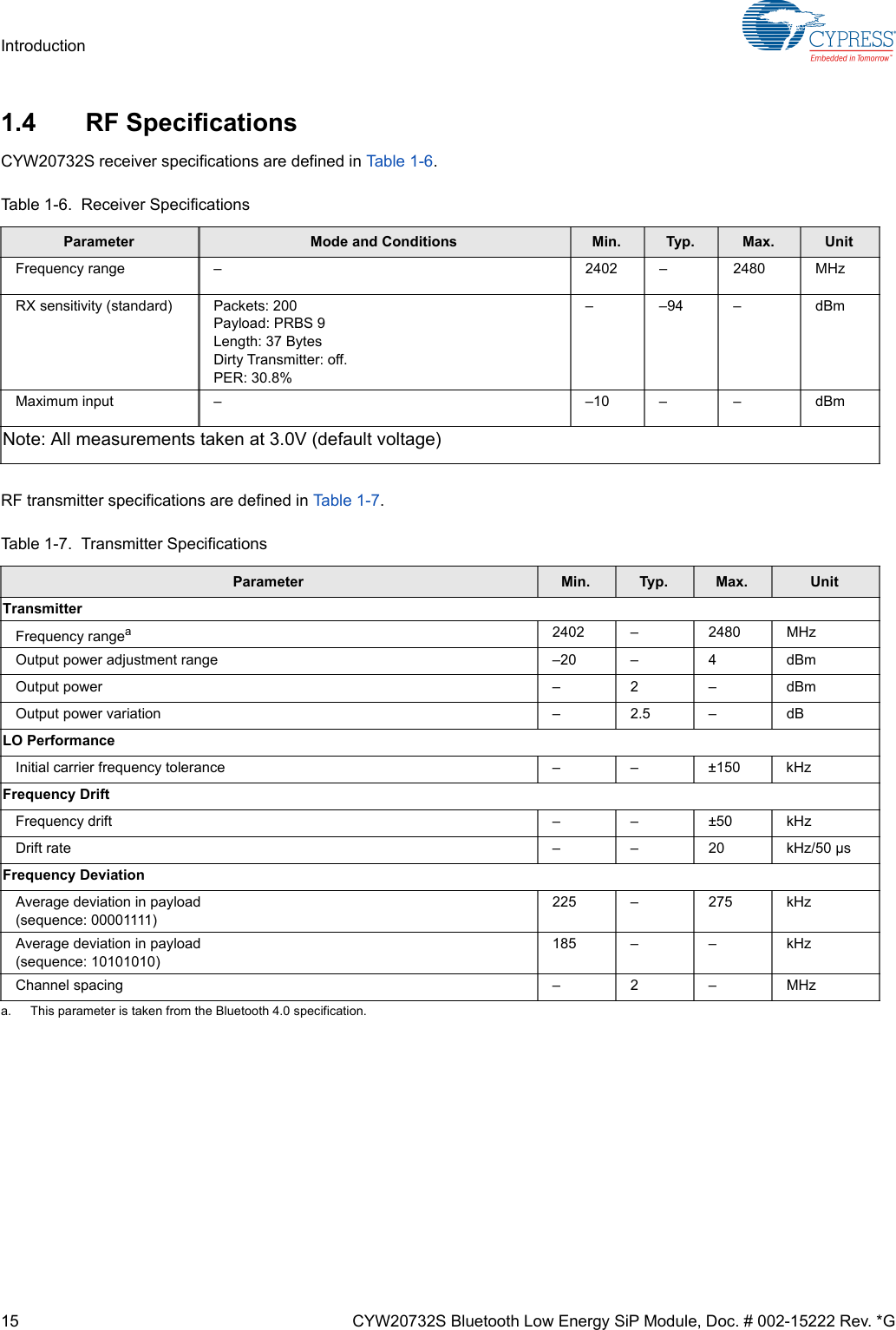
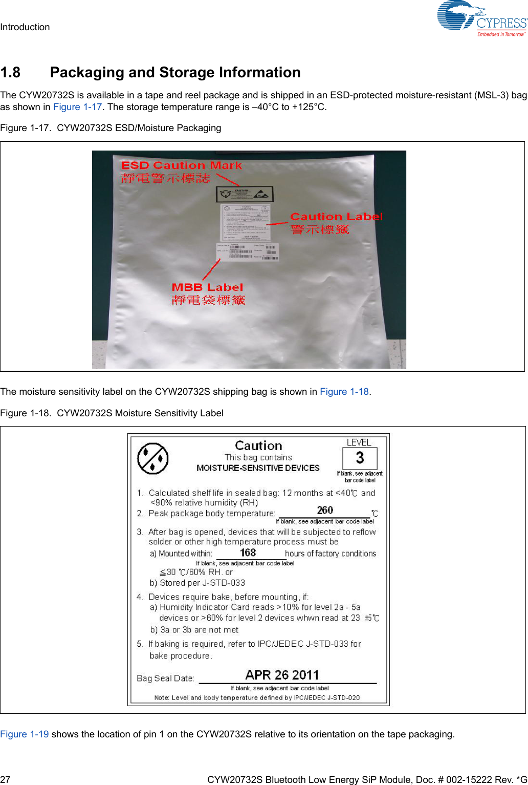
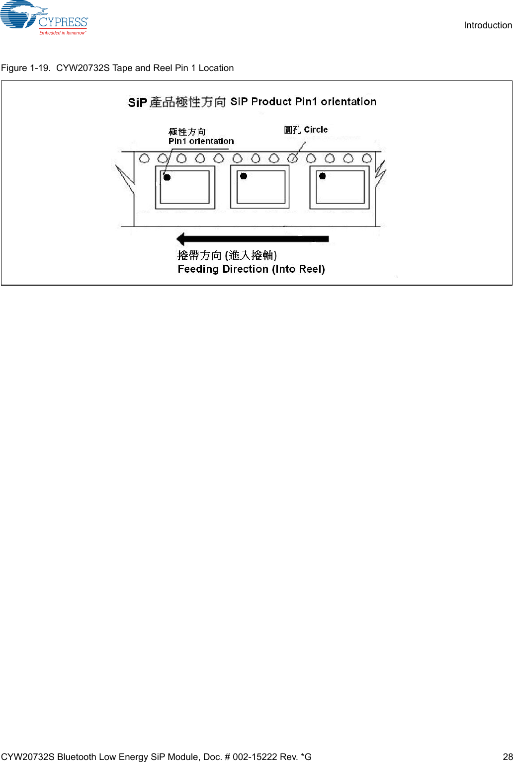
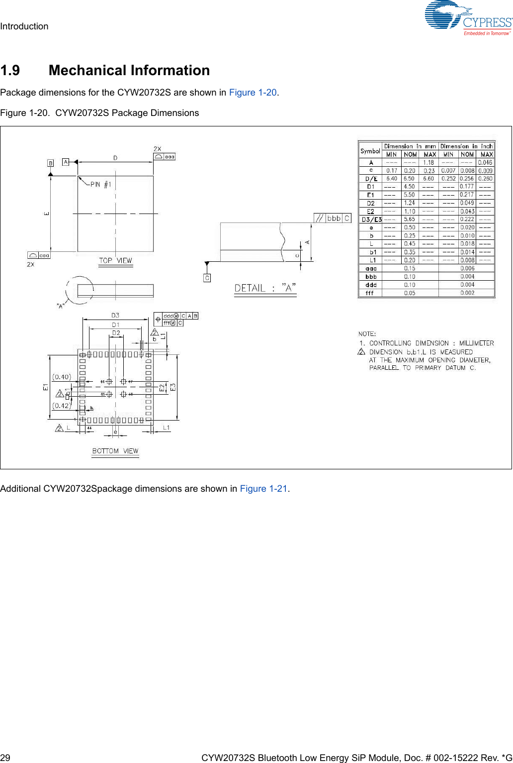
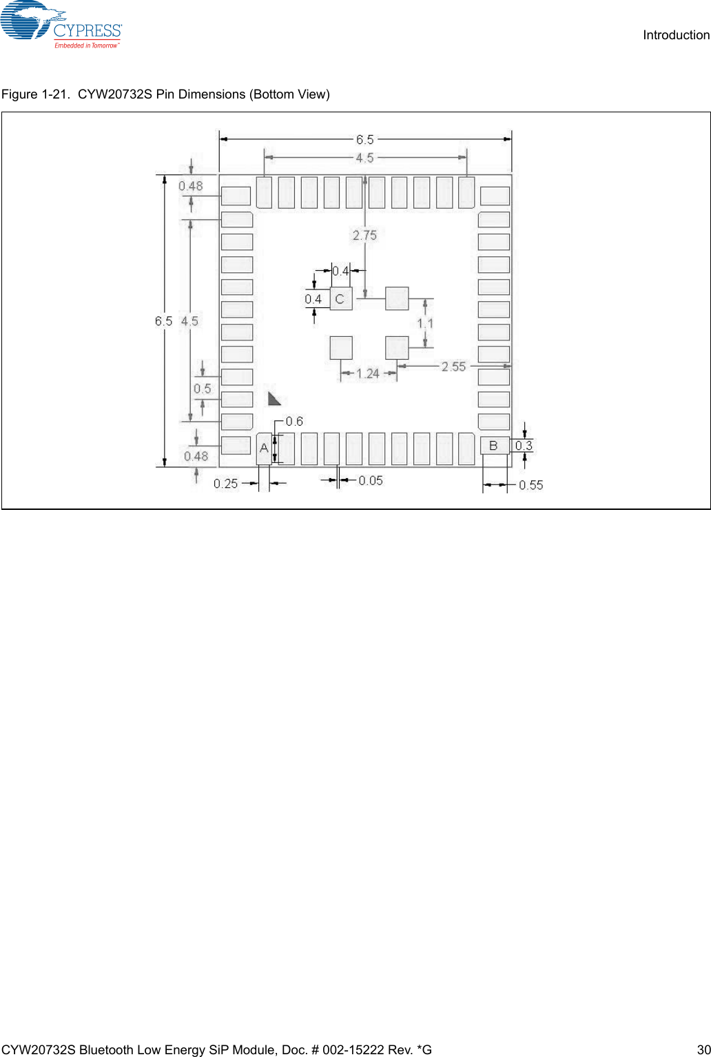
![3 CYW20732S Bluetooth Low Energy SiP Module, Doc. # 002-15222 Rev. *GPrefaceThis document provides descriptions of the interfaces, pin assignments, and specifications of Cypress CYW20732S Bluetooth Low Energy (BLE) System-in-Package (SiP) module. It is intended for designers who are responsible for adding the CYW20732S module to wireless input devices including heart-rate monitors, blood pressure monitors, proximity sensors, temperature sensors, and battery monitors.Cypress Part Numbering SchemeCypress is converting the acquired IoT part numbers from Broadcom to the Cypress part numbering scheme. Due to this con-version, there is no change in form, fit, or function as a result of offering the device with Cypress part number marking. Thetable provides Cypress ordering part number that matches an existing IoT part number.Acronyms and AbbreviationsIn most cases, acronyms and abbreviations are defined on first use.For a comprehensive list of acronyms and other terms used in Cypress documents, go to http://www.cypress.com/glossary.Document ConventionsThe following conventions may be used in this document:Technical SupportCypress provides a wealth of data at http://www.cypress.com/internet-things-iot to help you to select the right IoT device foryour design, and quickly and effectively integrate the device into your design. Cypress provides customer access to a widerange of information, including technical documentation, schematic diagrams, product bill of materials, PCB layout informa-tion, and software updates. Customers can acquire technical documentation and software from the Cypress Support Commu-nity website (http://community.cypress.com/).Table 2-1. Mapping Table for Part Number between Broadcom and CypressBroadcom Part Number Cypress Part NumberBCM20732 CYW20732BCM20732S CYW20732SConvention DescriptionBold User input and actions: for example, type exit, click OK, press Alt+CMonospaceCode: #include <iostream>HTML: <td rowspan = 3>Command line commands and parameters: wl [-l] <command>< > Placeholders for required elements: enter your <username> or wl <command>[] Indicates optional command-line parameters: wl [-l]Indicates bit and byte ranges (inclusive): [0:3] or [7:0]](https://usermanual.wiki/Cypress-Semiconductor/0737.User-Manual-CYW20732S-0514/User-Guide-3848775-Page-3.png)


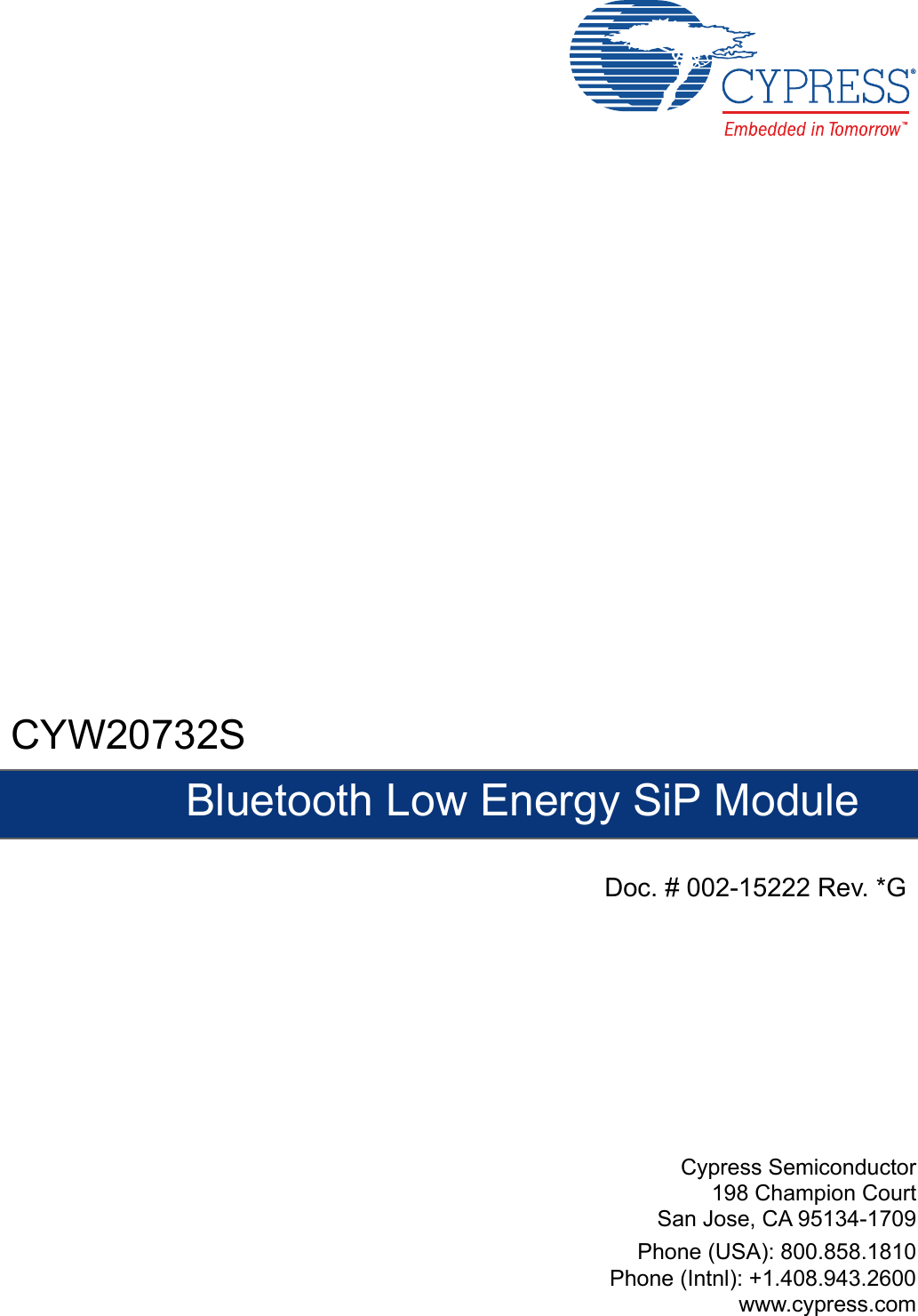
![PRELIMINARY'RFXPHQW1XPEHU5HY$ 3DJHRI5HJXODWRU\,QIRUPDWLRQ)&&)&&127,&(WKH)&&5XOHV7KHGHYLFHPHHWVWKHUHTXLUHPHQWVIRUPRGXODUWUDQVPLWWHUDSSURYDODVGHWDLOHGLQ)&&SXEOLF1RWLFH'$WUDQVPLWWHU2SHUDWLRQLVVXEMHFWWRWKHIROORZLQJWZRFRQGLWLRQV7KLVGHYLFHPD\QRWFDXVHKDUPIXOLQWHUIHUHQFHDQG7KLVGHYLFHPXVWDFFHSWDQ\LQWHUIHUHQFHUHFHLYHGLQFOXGLQJLQWHUIHUHQFHWKDWPD\FDXVHXQGHVLUHGRSHUDWLRQ&$87,217KH)&&UHTXLUHVWKHXVHUWREHQRWLILHGWKDWDQ\FKDQJHVRUPRGLILFDWLRQVPDGHWRWKLVGHYLFHWKDWDUHQRWH[SUHVVO\DSSURYHGE\&\SUHVV6HPLFRQGXFWRUPD\YRLGWKHXVHUVDXWKRULW\WRRSHUDWHWKHHTXLSPHQW7KLVHTXLSPHQWKDVEHHQWHVWHGDQGIRXQGWRFRPSO\ZLWKWKHOLPLWVIRUD&ODVV%GLJLWDOGHYLFHSXUVXDQWWR3DUWRIWKH)&&5XOHV7KHVHOLPLWVDUHGHVLJQHGWRSURYLGHUHDVRQDEOHSURWHFWLRQDJDLQVWKDUPIXOLQWHUIHUHQFHLQDUHVLGHQWLDOLQVWDOODWLRQ7KLVHTXLSPHQWJHQHUDWHVXVHVDQGFDQUDGLDWHUDGLRIUHTXHQF\HQHUJ\DQGLIQRWLQVWDOOHGDQGXVHGLQDFFRUGDQFHZLWKWKHLQVWUXFWLRQVrPD\FDXVHKDUPIXOLQWHUIHUHQFHWRUDGLRFRPPXQLFDWLRQV+RZHYHUWKHUHLVQRJXDUDQWHHWKDWLQWHUIHUHQFHZLOOQRWRFFXULQDSDUWLFXODULQVWDOODWLRQ,IWKLVHTXLSPHQWGRHVFDXVHKDUPIXOLQWHUIHUHQFHWRUDGLRRUWHOHYLVLRQUHFHSWLRQZKLFKFDQEHGHWHUPLQHGE\WXUQLQJWKHHTXLSPHQWRIIDQGRQWKHXVHULVHQFRXUDJHGWRWU\WRFRUUHFWWKHLQWHUIHUHQFHE\RQHRUPRUHRIWKHIROORZLQJPHDVXUHVn5HRULHQWRUUHORFDWHWKHUHFHLYLQJDQWHQQDn,QFUHDVHWKHVHSDUDWLRQEHWZHHQWKHHTXLSPHQWDQGUHFHLYHUn&RQQHFWWKHHTXLSPHQWLQWRDQRXWOHWRQDFLUFXLWGLIIHUHQWIURPWKDWWRZKLFKWKHUHFHLYHULVFRQQHFWHGn&RQVXOWWKHGHDOHURUDQH[SHULHQFHGUDGLR79WHFKQLFLDQIRUKHOS/$%(/,1*5(48,5(0(1767KH2ULJLQDO(TXLSPHQW0DQXIDFWXUHU2(0PXVWHQVXUHWKDW)&&ODEHOOLQJUHTXLUHPHQWVDUHPHW7KLVLQFOXGHVDFOHDUO\YLVLEOHODEHORQWKHRXWVLGHRIWKH2(0HQFORVXUHVSHFLI\LQJWKHDSSURSULDWH&\SUHVV6HPLFRQGXFWRU)&&LGHQWLILHUIRUWKLVSURGXFWDVZHOODVWKH)&&1RWLFHDERYH7KH)&&LGHQWLILHULV)&&,',QDQ\FDVHWKHHQGSURGXFWPXVWEHODEHOHGH[WHULRUZLWK&RQWDLQV)&&,' $17(11$:$51,1*7KLVGHYLFHLVWHVWHGZLWKDVWDQGDUG60$FRQQHFWRUDQGZLWKWKHDQWHQQDVOLVWHGEHORZ:KHQLQWHJUDWHGLQWKH2(0VSURGXFWWKHVHIL[HGDQWHQQDVUHTXLUHLQVWDOODWLRQSUHYHQWLQJHQGXVHUVIURPUHSODFLQJWKHPZLWKQRQDSSURYHGDQWHQQDV$Q\DQWHQQDQRWLQWKHIROORZLQJWDEOHPXVWEHWHVWHGWRFRPSO\ZLWK)&&6HFWLRQIRUXQLTXHDQWHQQDFRQQHFWRUVDQG6HFWLRQIRUHPLVVLRQV5)(;32685(7RFRPSO\ZLWK)&&5)([SRVXUHUHTXLUHPHQWVWKH2ULJLQDO(TXLSPHQW0DQXIDFWXUHU2(0PXVWHQVXUHWRLQVWDOOWKHDSSURYHGDQWHQQDLQWKHSUHYLRXV7KHSUHFHGLQJVWDWHPHQWPXVWEHLQFOXGHGDVD&$87,21VWDWHPHQWLQPDQXDOVIRUSURGXFWVRSHUDWLQJZLWKWKHDSSURYHGDQWHQQDVLQ7DEOHRQSDJHWRDOHUWXVHUVRQ)&&5)([SRVXUHFRPSOLDQFH$Q\QRWLILFDWLRQWRWKHHQGXVHURILQVWDOODWLRQRUUHPRYDOLQVWUXFWLRQVDERXWWKHLQWHJUDWHGUDGLRPRGXOHLVQRWDOORZHG7KHUDGLDWHGRXWSXWSRZHURI DQWHQQD)&&,' LVIDUEHORZWKH)&&UDGLRIUHTXHQF\H[SRVXUHOLPLWV1HYHUWKHOHVVXVH VXFKDPDQQHUWKDWPLQLPL]HVWKHSRWHQWLDOIRUKXPDQFRQWDFWGXULQJQRUPDORSHUDWLRQ(QGXVHUVPD\ QRW EH SURYLGHG ZLWK WKH PRGXOHLQVWDOODWLRQLQVWUXFWLRQV 2(0 LQWHJUDWRUV DQG HQGXVHUVPXVWEH SURYLGHGZLWKWUDQVPLWWHURSHUDWLQJFRQGLWLRQVIRUVDWLVI\LQJ5)H[SRVXUHFRPSOLDQFHThe device complies with part 15 ofWAP-0737WAP-0737the device with the PCB WAP-0737the device](https://usermanual.wiki/Cypress-Semiconductor/0737.User-Manual-CYW20732S-0514/User-Guide-3848775-Page-32.png)
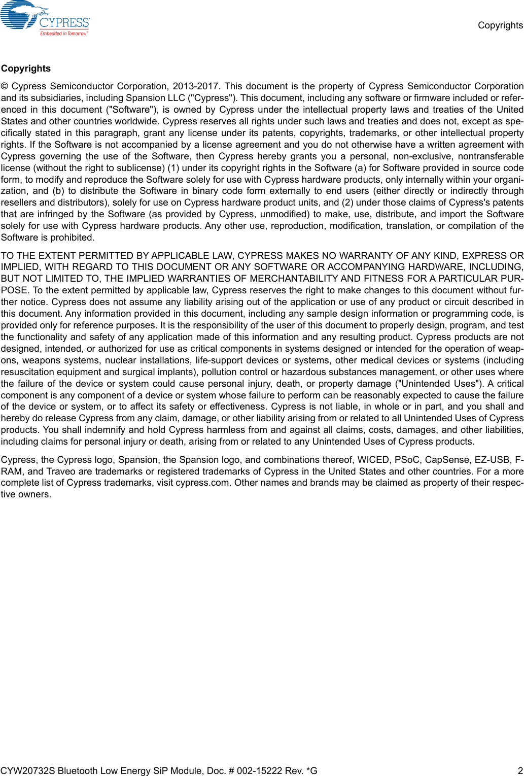
![PRELIMINARY &<%7&HUWLILFDWLRQLVOLFHQVHGWRPHHWWKHUHJXODWRU\U HTXLUHPHQWVRI,QGXVWU\&DQDGD,&/LFHQVH,&0DQXIDFWXUHUVRIPRELOHIL[HGRUSRUWDEOHGHYLFHVLQFRUSRUDWLQJWKLVPRGXOHDUHDGYLVHGWRFODULI\DQ\UHJXODWRU\TXHVWLRQVDQGHQVXUHFRPSOLDQFH IRU 6$5 DQGRU 5) H[SRVXUH OLPLWV 8VHUV FDQ REWDLQ &DQDGLDQ LQIRUPDWLRQ RQ 5) H[SRVXUH DQG FRPSOLDQFH IURPZZZLFJFFD7KLVGHYLFHKDVEHHQGHVLJQHGWRRSHUDWHZLWKWKHDQWHQQDVOLVWHGLQ7DEOHRQSDJHKDYLQJDPD[LPXPJDLQRI QQDVQRWLQFOXGHGLQWKLVOLVWRUKDYLQJDJDLQJUHDWHU G%LDUHVWULFWO\SURKLELWHGIRUXVHZLWKWKLVGHYLFH7KHUHTXLUHGDQWHQQDLPSHGDQFHLVRKPV7KHDQWHQQDXVHGIRUWKLVWUDQVPLWWHUPXVWQRWEHFRORFDWHGRURSHUDWLQJLQFRQMXQFWLRQZLWKDQ\RWKHUDQWHQQDRUWUDQVPLWWHU,&127,&(7KH GHYLFHLQFOXGLQJ WKH EXLOWLQ WUDFH DQWHQQD FRPSOLHV ZLWK &DQDGD 566*(1 5XOHV 7KH GHYLFH PHHWVWKHUHTXLUHPHQWVIRUPRGXODUWUDQVPLWWHUDSSURYDODVGHWDLOHGLQ566*(12SHUDWLRQLVVXEMHFWWRWKHIROORZLQJWZRFRQGLWLRQV7KLVGHYLFHPD\QRWFDXVHKDUPIXOLQWHUIHUHQFHDQG7KLVGHYLFHPXVWDFFHSWDQ\LQWHUIHUHQFHUHFHLYHGLQFOXGLQJLQWHUIHUHQFHWKDWPD\FDXVHXQGHVLUHGRSHUDWLRQ,&5$',$7,21(;32685(67$7(0(17)25&$1$'$7KLVGHYLFHFRPSOLHVZLWK,QGXVWU\&DQDGDOLFHQFHH[HPSW566VWDQGDUGV2SHUDWLRQLVVXEMHFWWRWKHIROORZLQJWZRFRQGLWLRQVWKLVGHYLFHPD\ QRW FDXVH LQWHUIHUHQFH DQG WKLVGHYLFHPXVWDFFHSWDQ\LQWHUIHUHQFHLQFOXGLQJLQWHUIHUHQFHWKDWPD\FDXVHXQGHVLUHGRSHUDWLRQRIWKHGHYLFH/HSUpVHQWDSSDUHLOHVWFRQIRUPHDX[&15G,QGXVWULH&DQDGDDSSOLFDEOHVDX[DSSDUHLOVUDGLRH[HPSWVGHOLFHQFH/H[SORLWDWLRQHVWDXWRULVpHDX[GHX[FRQGLWLRQVVXLYDQWHVODSSDUHLOQHGRLWSDVSURGXLUHGHEURXLOODJHHWOXWLOLVDWHXUGHODSSDUHLOGRLWDFFHSWHUWRXWEURXLOODJHUDGLRpOHFWULTXHVXELPrPHVLOHEURXLOODJHHVWVXVFHSWLEOHGHQFRPSURPHWWUHOHIRQFWLRQQHPHQW/$%(/,1*5(48,5(0(1767KH2ULJLQDO(TXLSPHQW0DQXIDFWXUHU2(0PXVWHQVXUHWKDW,&ODEHOOLQJUHTXLUHPHQWVDUHPHW7KLVLQFOXGHVDFOHDUO\YLVLEOHODEHORQWKHRXWVLGHRIWKH2(0HQFORVXUHVSHFLI\LQJWKHDSSURSULDWH&\SUHVV6HPLFRQGXFWRU,&LGHQWLILHUIRUWKLVSURGXFWDVZHOODVWKH,&1RWLFHDERYH7KH,&LGHQWLILHULV ,QDQ\FDVHWKHHQGSURGXFWPXVWEHODEHOHGLQL WVH[WHULRUZLWK&RQWDLQV,&(XURSHDQ577('HFODUDWLRQRI&RQIRUPLW\+HUHE\&\SUHVV6HPLFRQGXFWRUGHFODUHVWKDWWKH%OXHWRRWKPRGXOHFRPSOLHVZLWKWKHHVVHQWLDOUHTXLUHPHQWVDQGRWKHUUHOHYDQWSURYLVLRQVRI'LUHFWLYH(&$VDUHVXOWRIWKHFRQIRUPLW\DVVHVVPHQWSURFHGXUHGHVFULEHGLQ$QQH[,,,RIWKH'LUHFWLYH(&WKHHQGFXVWRPHUHTXLSPHQWVKRXOGEHODEHOHGDVIROORZV$OOYHUVLRQVRIWKH UHIHUHQFHGHVLJQFDQEHXVHGLQWKHIROORZLQJFRXQWULHV$XVWULD%HOJLXP&\SUXV&]HFK5HSXEOLF'HQPDUN(VWRQLD)LQODQG)UDQFH*HUPDQ\*UHHFH+XQJDU\,UHODQG,WDO\/DWYLD/LWKXDQLD/X[HPERXUJ0DOWD3RODQG3RUWXJDO6ORYDNLD6ORYHQLD6SDLQ6ZHGHQ7KH1HWKHUODQGVWKH8QLWHG.LQJGRP6ZLW]HUODQGDQG1RUZD\ISEDThe device7922A-0737-1.5dBi, antethan -1.5(3) No SAR evaluation is required since maximum transmitter Pout is below IC threshold(3) Aucune évaluation SAR n'est requise étant donné que la puissance maximale de l'émetteur est inférieure au seuil IC.7922A-07377922A-0737device in the specified](https://usermanual.wiki/Cypress-Semiconductor/0737.User-Manual-CYW20732S-0514/User-Guide-3848775-Page-33.png)