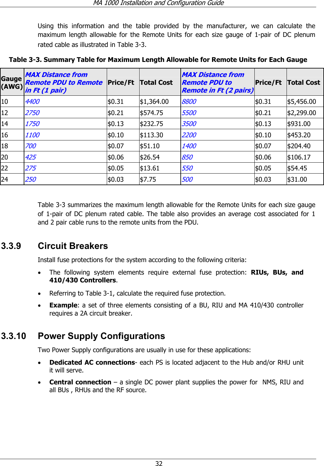
Corning Optical Communication MA1K-IDEN-SMR RF Booster User Manual MobileAccess 2000

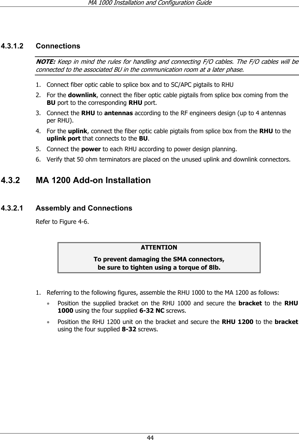
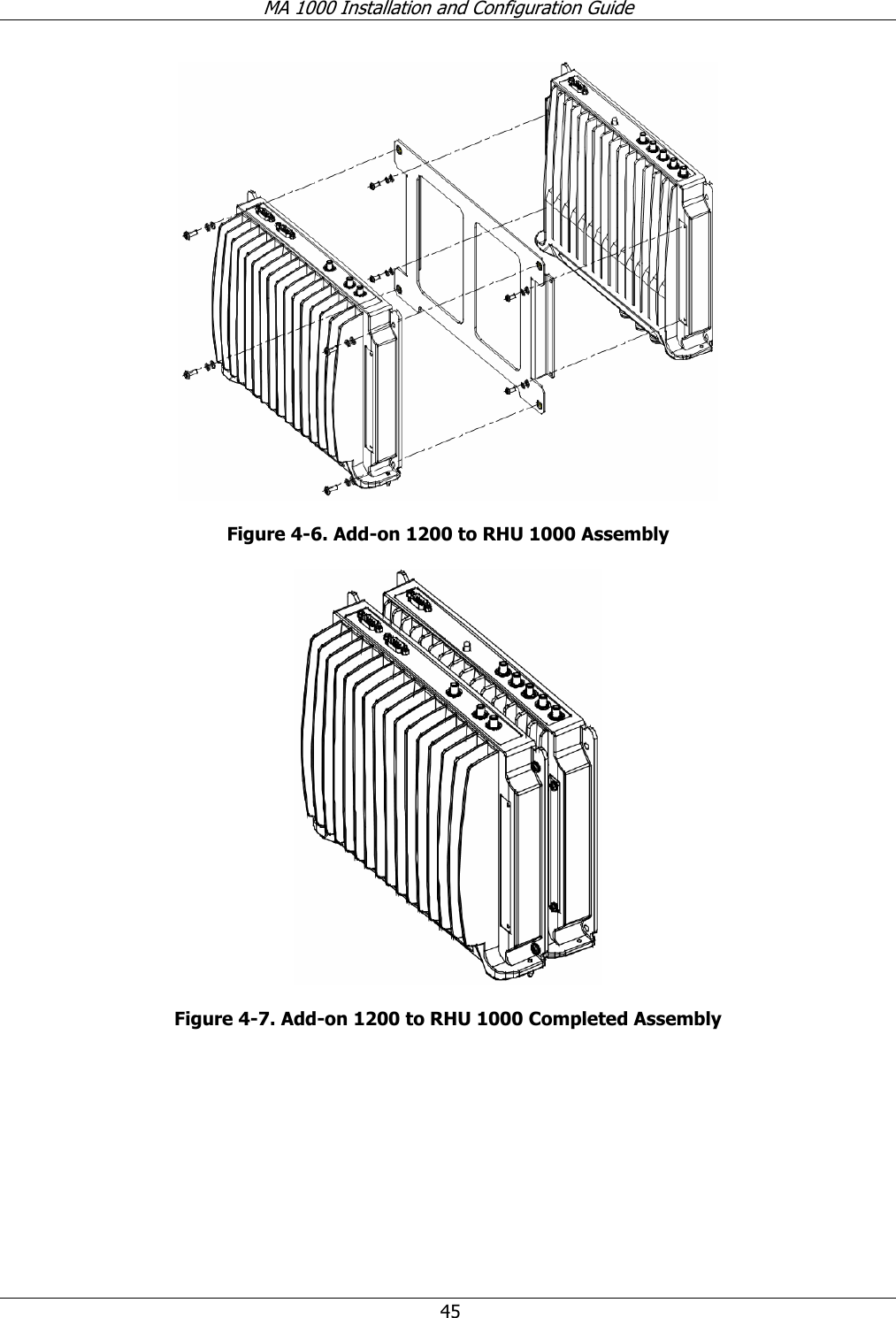
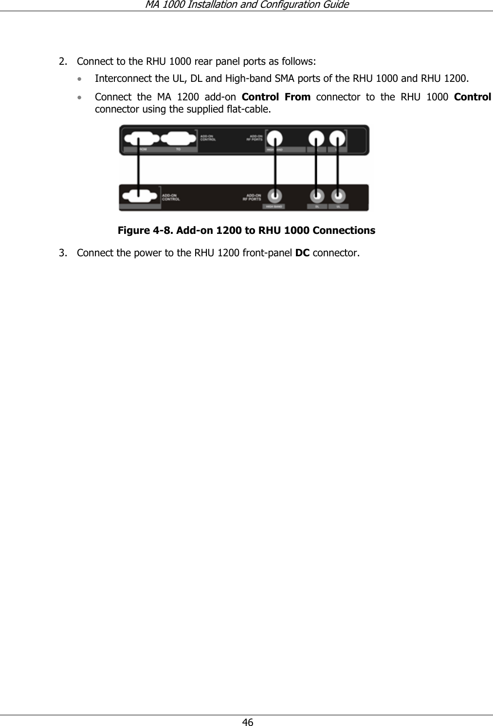
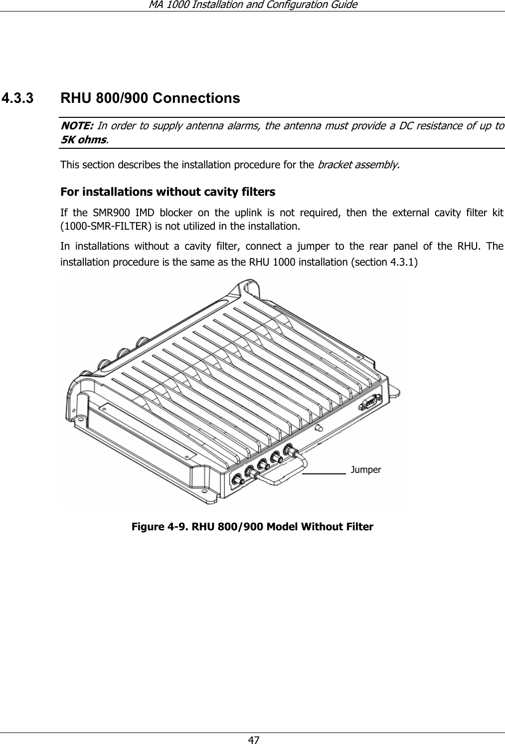
Corning Optical Communication Wireless RF Booster MobileAccess 2000

Contents

Users Manual Part 3

MA 1000 Installation and Configuration Guide  31  3.3.8  DC Cable Length Design from Base Units to Remote Units NOTE: Please refer to MOPS_091482_R1_Micrin_inbuilding System for more information. A primary concern when installing lengths of wire is voltage drop. The amount of voltage lost between the originating power supply and the device being powered can be significant. Improper selection of wire gauge can lead to an unacceptable voltage drop at load end.  A DC cable manufacturers chart1 can be used to design the proper cable size for the desired length by calculating the voltage drop of a pair wire as a function of wire gauge and load current. To determine the Load Current for MobileAccess-1000 remote units, it is required to consider the following when identifying the proper cable size (default specifications): • Remote unit power consumption: 75 Watts Maximum (includes 800 and 900 MHz and 1.9 MHz) • Remote unit operating voltage range:  • MA 1000: -20 to –60 VDC  • MA 1200: -25 to –60 VDC  NOTES:  1. A paired wire run represents the feed and return line to the load. For example, a500-foot wire pair is equivalent to 1000 feet of total wire. 2.  For all in-building systems always use PLENUM RATED DC cable. 3. For all purposes and precaution measures are calculations will use –26 VDC as the lower range voltage for Remote Units.  Therefore, to calculate the Load Current we simply divide the maximum power consumption specified for the remote unit over the minimum voltage required operating the Remote Unit (-21 VDC).  The Load Current calculated for each Remote Unit will be 2.38 amps. Table  3-2. MobileAccess-1000 DC Cable Requirements  to Power Remotes Units from the PDU Parameter  Value  Units Minimum VDC @ Remote  21  VDC Remote Power Consumption  50  Watts Current Load @ Remote  2.380952381  Amps                                                       1 Appendix B: Manufacturers Chart to Determine Cable Size for 1-pair of Plenum Rated Cable
MA 1000 Installation and Configuration Guide  32 Using this information and the table provided by the manufacturer, we can calculate the maximum length allowable for the Remote Units for each size gauge of 1-pair of DC plenum rated cable as illustrated in Table  3-3. Table  3-3. Summary Table for Maximum Length Allowable for Remote Units for Each Gauge Gauge (AWG) MAX Distance from Remote PDU to Remote in Ft (1 pair) Price/Ft  Total Cost MAX Distance from Remote PDU to Remote in Ft (2 pairs) Price/Ft  Total Cost10 4400 $0.31 $1,364.00 8800 $0.31 $5,456.00 12 2750 $0.21 $574.75 5500 $0.21 $2,299.00 14 1750 $0.13 $232.75 3500 $0.13 $931.00 16 1100 $0.10 $113.30 2200 $0.10 $453.20 18 700 $0.07 $51.10 1400 $0.07 $204.40 20 425 $0.06 $26.54 850 $0.06 $106.17 22 275 $0.05 $13.61 550 $0.05 $54.45 24 250 $0.03 $7.75 500 $0.03 $31.00  Table  3-3 summarizes the maximum length allowable for the Remote Units for each size gauge of 1-pair of DC plenum rated cable. The table also provides an average cost associated for 1 and 2 pair cable runs to the remote units from the PDU. 3.3.9 Circuit Breakers Install fuse protections for the system according to the following criteria:  • The following system elements require external fuse protection: RIUs, BUs, and 410/430 Controllers. • Referring to Table  3-1, calculate the required fuse protection.  • Example: a set of three elements consisting of a BU, RIU and MA 410/430 controller requires a 2A circuit breaker. 3.3.10  Power Supply Configurations Two Power Supply configurations are usually in use for these applications:  • Dedicated AC connections- each PS is located adjacent to the Hub and/or RHU unit it will serve. • Central connection – a single DC power plant supplies the power for  NMS, RIU and all BUs , RHUs and the RF source.
MA 1000 Installation and Configuration Guide  33  3.3.11  Types of Power Supplies MobileAccess will be powered based on the type of in building application: 1) EBTS Driven Configuration. In this configuration, existing Nextel approved power plants shall be used to power both the MobileAccess equipment and Motorola EBTS equipment, RFN MC Series IDEN Microcell (commonly know as Aztec), or BDA units..  2) 120/220 VAC. Can be used with separate PS to power the MobileAccess equipment and a BDA. If there aren’t any power back-up requirements for the in-building solution. NOTE: It is vital to Calculate the required power according to the requirements of the specific installation and then determine the configuration of the power supplies and/or plant. Refer to  3.3.5 for power requirements for MobileAccess elements and use standard Nextel power consumption requirements for the RF source being applied.  3.4 Installation Conventions Some of the basic installation conventions are listed below for the MA 1000 system: • Base Units – are usually concentrated in the same location, most often in the main communication room.  • Remote Hub Units usually placed in the communication shaft or closet of a corresponding floor so they can be easily located.  Each RHU can typically cover a floor of up to 30,000 sq ft.  • One or two pair plenum rated source power cable – a  one or two pair gauge power cable run from the communication room through the building shaft. The power is distributed to each remote unit using these power DC cables that provide power to the individual RHUs on each floor. • Fiber optic cable - bundled fibers are terminated into the Base Units in the main communication room.  The fibers are then routed to each coverage location where individual fibers terminate into splice boxes.  The splice box couples the installed fiber into the remote units.  Enough spare fibers should be installed to take into account future expansion of the system.   For example, for three remote units, six fibers are required. However, to allow for future upgrades, it is recommended to install additional optic fibers to be connected to additional RHUs.
MA 1000 Installation and Configuration Guide  34 The following figure illustrates fiber optic routing sufficient to cover 21 floors: each group of strands can cover three floors as illustrated below, with two strands to spare. The first group of strands coves floors 1, 2 and 3; the next group will cover floors 4, 5 and 6 through an additional splice box.  Figure  3-1. Illustration of Fiber Optic Routing  • For remote power supply configuration - cable bundles are routed from the main communication room and individual wire pairs are terminated into the power feed of individual units.   By providing power from a single distribution point, maintenance can be reduced and UPS backup can be easily provided. The maximum distance from the source to the termination spot is 1000 feet using 18 gauge wires.   In many locations local codes do not require power to be run through conduit if 100 watts or less is used.  Please consult the regulations in your local jurisdiction prior to deploying remote power.  When power cables require distances greater than 1000 feet 14 or 16 gauge wire may be used.    • On each floor - the antennas are connected to the RHUs using coax cables.
MA 1000 Installation and Configuration Guide  35 44  SSyysstteemm  IInnssttaallllaattiioonn  4.1 Overview This chapter describes how the communication room and remote locations are installed. The individual system elements are described in Chapter 2.  In order to describe the installation process clearly, it will be described as consisting of two logical parts:  A. Telecommunications room – installing the RIUs,  BUs,  MA 410/430 controllers, and the required passive equipment in the telecommunication room close to the RF signal source. This installation may differ between single  and multi-building topologies. B. Remote locations –  RHU  and  Add-on installations and connections. These are usually wall mounts.  The installations for two basic topologies are described in detail: for single building and for multi-building. By understanding the two generic installations you will be able to address any variations in system deployment. NOTE: For installations that include the MA NMS: Once the installation has been completed, it can be verified using the MCT application (NMS User’s Guide) and the devices monitored using the NMS Manager (NMS User’s Guide). 4.2 Communication Room Installation 4.2.1  Rack Installation Safety Instructions Review the following guidelines to help ensure your safety and protect the equipment from damage during the installation. • Only trained and qualified personnel should be allowed to install or replace this equipment. • Verify that ambient temperature of the environment does not exceed 50°C (122°F) • To maintain a low center of gravity, ensure that heavier equipment is installed near the bottom of the rack and load the rack from the bottom to the top.
MA 1000 Installation and Configuration Guide  36 • Ensure that adequate airflow and ventilation within the rack and around the installed components so that the safety of the equipment is not compromised. It is recommended to allow for at least about 2 cm of airspace between devices in the rack. • Verify that the equipment is grounded as required – especially the supply connections. 4.2.2  Rack Installation Procedure (Motorola Controller Rack) It is recommended to install the following MobileAccess system modules in the Motorola Controller 19” rack (usually in the communication room): NOTE: For more information on configuration rack layout refer to MOPS_091482_R1_Micrin_inbuilding System.doc • RIU 3U • BU 1U  • MobileAccess 410/430 controller 1U • Power Distribution Units (Micrin 6-Channel and 8 Channel PDU units – for more information refer to MOPS 091482 R1 Micrin in building System. Motorola ISC, EAS and CSU units 1U each. • RF Interface panel (Weinchel Panel – for more information refer to MOPS_092265_R1_Weinschel_Inbuilding System)  Note: Verify that the rack height can support all the units to be installed, where you may also want to consider future expansions.
MA 1000 Installation and Configuration Guide  37 The following image describes shows the recommended locations of the MobileAccess elements in the rack in order to facilitate and simplify the cabling connections.  Note that the MobileAccess 410/430 controller is at eye level to provide an easy view of the LED indicators and LCD display and easy access to the local and remote monitoring connections.   Motorola Breaker Panel - 2UMain DAS PDU  - 1U (6-Channel PDU - Micrin)Radio Interface UnitMobileAccess - 3UBase Unit #1 MobileAccess - 1URemote DAS PDU #1 - 1U (8 Channel PDU - Micrin)EAS - 1UISC3 - 1UISC3 - 1UBase Unit #2 MobileAccess - 1URemote DAS PDU #2 - 1U (8 Channel PDU - Micrin)NMS MobileAccess - 1UBase Unit #4 MobileAccess - 1URemote DAS PDU #4 - 1U (8 Channel PDU - Micrin)CSU - 1UBase Unit #3 MobileAccess - 1URemote DAS PDU #3 - 1U (8 Channel PDU - Micrin)48 VDCSourceFrom PowerPlant (10 AmpDC Breaker)48 VDCSourceFrom PowerPlant (20 AmpDC Braker/Remote PDU)48 VDCSourceFrom PowerPlant (20 AmpDC Braker/Remote PDU)Using PlenumRated 2-pair DCCableTo Remote UnitsDC Wiring Standard for a CNTL Rack EBTS DrivenSystem Figure  4-1: Recommended Order In Motorola Controller Rack
MA 1000 Installation and Configuration Guide  38   4.2.3  Single Building Rack Installation This section provides an example of a single building main communication room installation for a 24-floor building with Cellular and PCS coverage. Since there are 24 floors, then 24 MA RHUs are required – one for each floor. In addition, the following equipment will be installed in the main communication room: • Three BUs – to support 24 RHUS • One MA 430 controller for monitoring  • One RIU with Cellular and PCS BTSCs – to interface to the BTS/BDA  Figure  4-2. Example of Single-building Topology Communication Room Installation
MA 1000 Installation and Configuration Guide  39  4.2.4 Multi-Building Rack Installation Figure  4-3 provides an example of a multi-building solution which distributes two bands over a main site and two remote sites. Each site consists of an 8-floor building, requiring 8 RHUS per building (one on each floor).  The following equipment is required in the main communication room of each building: • One BU – each BU distributes a high-band and low-band signal from a dedicated operator to eight RHUs (housed in eight separate RCs – one on each floor).  • One MA 430 controller configured as Master in the Main building, and two MA 410 controllers configured as slaves in the Remote buildings. • MA 300 Main in the main building, and MA 300 Slave in each of the remote buildings.  The MA 300 units extend the RF signal from the Main to the Remote buildings over a single strand of fiber.  Uplink and downlink signal are placed on the single fiber at 1310 and 1550 respectively.    Figure  4-3. Example of Multi-building Topology Communication Room Installation
MA 1000 Installation and Configuration Guide  40  4.2.5 RIU Connections The rear-panel provides all the connections on the BTS side and on the BU side as well as connections to the MobileAccess 410/430 controller and the power connection. Two types of BTS side connections are available for each BTS conditioner: simplex and duplex.  ATTENTION 1. The RIU is factory set to 8dB gain on the uplink and 0 dB gain in the downlink. In order to operate properly, an ADJUSTMENT process is required in the field. 2. Any unused input and output connectors MUST be terminated with 50 ohms – otherwise the ADJUSMENT procedure results may be affected.  4.2.5.1 Basic Connections Connect each BU to the corresponding RF Uplink and Downlink connectors on the RIU rear panel.  Note that one uplink and one downlink  RIU rear-panel ports are used to connect one OPTM (four ports from the BU); two uplink and two downlink ports are used to connect an 8-port BU (two OPTMs).        Figure  4-4. RIU Rear Panel showing the RF Connection MobileAccess 1000 BU connections (pair per BU)  Power Controller connectionBTS/BDA duplex connectionsBTS/BDA simplex  connections
MA 1000 Installation and Configuration Guide  41 Each RIU can be connected to four 8-port Base Units (real panel connections) or eight 4-port Base Units.  The RIU can be expanded to support additional BU by using splitters and combiners connected to the front panel connectors.   Note: All connections are via RG223 coax cables with 1/2" N-type male connectors 1. Connect each BTS/BDA to the corresponding rear panel BTSC connectors. For each BTSC connection, both simplex and duplex connections are available: • For a duplex connection, connect to the BTSC DUP port; • For a simplex connection, connect to the BTSC UL and DL ports;  2. Connect the Power connections on the RIU rear panel. 3. If your system includes a MA 410/430 controller, connect the RS485 port on the RIU rear panel to the controller.     4.2.5.2  Connections to Additional BUs  To connect more than four 8-port BUs or more than eight 4-port BUs to the RIU, Connect an 8W splitter to the Downlink  connector on the RIU front panel and an 8W combiner to the Uplink connector on the RIU front panel and connect additional BUs to the uplink and downlink connections.  Expansion portsBTSCBTSCBTSCBTSCBTSCBTSCCombiners /Splitters Compartment*UL and DL connections to four BU8 modulesUL and DL connections to up to four additional BU8 modulesExternal 1:8 splitter /combiner
MA 1000 Installation and Configuration Guide  42  4.2.6 BU Connections NOTE:  It is assumed that the patch panel cabinet (SC/APC adaptors) for fiber optic cable connections is installed in the rack near the BUs.  1. Connect (3/125/900) pigtail with SC/APC connectors between splice tray and patch panel cabinet.  2. Connect (3/125/3000) SC/APC jumpers between the corresponding BU and patch panel.  3. Connect the fiber optic cables from the BU to the RHUs through the patch panel cabinet.  4. Connect the UL RF Output and DL RF Input connectors to the RIU or UL and DL connectors or to the passive interface (such as Interface Box) in topologies that do not include RIUs. 4.2.7 Controller Connections Refer to the MobileAccess NMS 410/430 Installation and Configuration Guide for connections.
MA 1000 Installation and Configuration Guide  43 4.3 Remote Site Installation 4.3.1  RHU 1000 Installation  Mount and install each RHU on the wall in the communication shaft or communication room.  4.3.1.1 Wall Mount RHU 1000 is usually mounted on a wall in a clean indoor environment – RF ports facing down.  Assembly instructions 1. Place the unit against the wall and mark the four holes to be drilled in the wall. 2. Drill four holes 8mm in diameter and insert the appropriate sized plastic plugs in each hole.  3. Secure the RHU 1000 to the wall using four screws, 4.5mm diameter, 40 mm long.  Figure  4-5. RHU 1000 Wall Mount
MA 1000 Installation and Configuration Guide  44  4.3.1.2 Connections NOTE: Keep in mind the rules for handling and connecting F/O cables. The F/O cables will be connected to the associated BU in the communication room at a later phase.  1. Connect fiber optic cable to splice box and to SC/APC pigtails to RHU  2. For the downlink, connect the fiber optic cable pigtails from splice box coming from the BU port to the corresponding RHU port.  3. Connect the RHU to antennas according to the RF engineers design (up to 4 antennas per RHU).  4. For the uplink, connect the fiber optic cable pigtails from splice box from the RHU to the uplink port that connects to the BU.  5. Connect the power to each RHU according to power design planning.   6. Verify that 50 ohm terminators are placed on the unused uplink and downlink connectors. 4.3.2  MA 1200 Add-on Installation  4.3.2.1 Assembly and Connections Refer to Figure  4-6.  ATTENTION To prevent damaging the SMA connectors,  be sure to tighten using a torque of 8lb.  1. Referring to the following figures, assemble the RHU 1000 to the MA 1200 as follows: • Position the supplied bracket on the RHU 1000 and secure the bracket  to the RHU 1000 using the four supplied 6-32 NC screws. • Position the RHU 1200 unit on the bracket and secure the RHU 1200 to the bracket using the four supplied 8-32 screws.
MA 1000 Installation and Configuration Guide  45  Figure  4-6. Add-on 1200 to RHU 1000 Assembly   Figure  4-7. Add-on 1200 to RHU 1000 Completed Assembly
MA 1000 Installation and Configuration Guide  46  2. Connect to the RHU 1000 rear panel ports as follows: • Interconnect the UL, DL and High-band SMA ports of the RHU 1000 and RHU 1200. • Connect the MA 1200 add-on Control From connector to the RHU 1000 Control connector using the supplied flat-cable.  Figure  4-8. Add-on 1200 to RHU 1000 Connections 3. Connect the power to the RHU 1200 front-panel DC connector.
MA 1000 Installation and Configuration Guide  47   4.3.3  RHU 800/900 Connections NOTE: In order to supply antenna alarms, the antenna must provide a DC resistance of up to 5K ohms. This section describes the installation procedure for the bracket assembly.  For installations without cavity filters If the SMR900 IMD blocker on the uplink is not required, then the external cavity filter kit (1000-SMR-FILTER) is not utilized in the installation.  In installations without a cavity filter, connect a jumper to the rear panel of the RHU. The installation procedure is the same as the RHU 1000 installation (section  4.3.1)  Figure  4-9. RHU 800/900 Model Without Filter Jumper
MA 1000 Installation and Configuration Guide  48 Installations with cavity filters The required connections to the filter are implemented at the rear of the assembly as illustrated below. Additional connections are provided for connection to MA 1200 CELL/1900 add-on unit (refer to section  4.3.4).  Figure  4-10. Rear View of RHU 800/900 with Filter   4.3.3.1 Wall Mount RHU 800/900 is usually mounted on a wall in a clean indoor environment – RF ports facing down.  Assembly instructions 1. Place the unit against the wall and mark the four bracket holes to be drilled in the wall. 2. Drill four holes 8mm in diameter and insert the appropriate sized plastic plugs in each hole.  3. Secure the RHU 800/900 assembly to the wall using four screws, 4.5mm diameter, 40mm long. 4.3.3.2 Connections 1. Install splice box near RHU. 2. Connect fiber optic cable to splice box and to SC/APC pigtails to RHU  3. For the downlink, connect the fiber optic cable pigtails from splice box coming from the Base Unit port to the corresponding RHU port.  4. Connect the RHU antennas according to the RF engineers design. (Up to 4 antennas per RHU).
MA 1000 Installation and Configuration Guide  49 5. For the uplink, connect the fiber optic cable pigtails from splice box from the RHU to the uplink port that connects to the BU.  6. Connect the power to each RHU according to power design planning (local or remote power supply).   7. Verify that 50 ohm terminators are placed on the unused uplink and downlink connectors. 4.3.4  MA 800/900 Connections to MA 1200 Cell/1900 Add-on An additional band (CELL/1900) can be added to MA 800/900 installations by connecting the MA 1200 CELL 1900 add-on unit to the MA 800/900 RHU.  RHU 1200 add-on is simply assembled on top of the RHU 800/900 using the supplied plate, and the control ports and RF signal ports for each band are interconnected. The signals are distributed through the RFU 800/900 antenna connections.  The add-on unit does not require any additional RF or optic infrastructure since all signals are received through the RHU 800/900 unit to which the add-on is assembled.   Figure  4-11. RHU 800/900 and CELL 1900 Add-on Front View Referring to Figure  4-13, assemble the add-on unit to the Rhu 800/900 as follows: 1. Position the supplied plate on the RHU 800/900 and secure it to the RHU 800/900 using the four supplied 6-32 NC screws.  RHU 800/900 Antenna connections (four) PlateAdd-on
MA 1000 Installation and Configuration Guide  50 2. Position the RHU 1200 unit on the plate and secure the RHU 1200 to the plate using the four supplied 8-32 screws.  3. Referring to the following figure, connect the add-on connections: ATTENTION: To prevent damaging the SMA connectors,  be sure to tighten the connection using a torque of 8lb. • Interconnect the RHU 800/900 and RHU 1200 SMA Uplink,  Downlink and High connectors on the rear panels of both units using the three straight jumpers.  • Interconnect the RHU 800/900 and RHU 1200 D-type 9-pin connectors on the rear panels of both units using the supplied flat-cable.   Figure  4-12. Connections to MA 1200 add-on The following figure illustrates the rear panel connections to the add-on and filter.  Figure  4-13. RHU 800/900 and CELL 1900 Add-on Rear View 4. Connect the power to the RHU 1200 front-panel DC connector.
MA 1000 Installation and Configuration Guide  51   4.3.5 Antenna Connections • For systems without MA 850 modules - connect the antenna connections to the RHU antenna ports; • For systems with MA 850 modules - refer to the MA 850 Installation and Configuration Guide and connect the antenna ports to the MA 850.  4.4 Power Distribution Units  NOTE: For more information refer to Nextel Communications MOPS_091482_R1_Micrin_inbuilding System document. The Micrin Power Distribution Units were designed specifically to be integrated into the  MobileAccess system.  The units provide access to up to –48 VDC power to all of MobileAccess-1000 units from a central DC power source, as well as access to a – 48 V DC battery back-up systems from our standard approved power plant configurations.  Two Power Distribution Units are available: a 6-channel PDU (Main PDU) and an 8-channel PDU (Remote PDU.)   • Main PDU unit - provides DC power to MobileAccess-1000 host units that are located in a 19-inch wide rack (i.e. Base Units (BU), Network Manger System (NMS) and the Radio Interface Unit (RIU)).  • The Remote PDU units - functions as a centralized DC power source to supply DC power to all MobileAccess-1000 remote units. Each Remote PDU can provide power to up to 8 remotes. Each remote unit powered by the Remote PDU will be protected by a dedicated circuit breaker corresponding to the power consumption of each remote unit (3A).  Power to the remote units can be provided either through separate copper cables or mixed bundled fiber-copper cables. To guarantee safety to our in-building customers, the PDU is UL approved to meet NEC Class 2 power source requirements for centralized DC power systems.  Each PDU unit requires a dedicated DC breaker. For a full size one sector MobileAccess-1000 system, four breakers are required. Sizes and alternatives will be discussed in the following section.   The PDU units rear panel input and output connections have been designed to optimize cable layout to the MobileAccess-1000 system and from the power plant. Labels to the breakers in front will make it easy to manage, maintain and operate the in-building system.
MA 1000 Installation and Configuration Guide  52  PDU Main Features: • 19-inch sub-rack design • 1 rack unit • Short circuit protection to all units • DC remote centralized power   4.4.1  PDU Part Description:      Figure  4-14: Micrin MTC2931 8-channel PDU (Remote PDU)            Figure  4-15: Micrin MTC2980 6-channel PDU (Main PDU) Short-circuit breaker switch protection for each Remote Unit Main Power Source Input from Power plant (-48 VDC) Supply Outputs to Remote Units (-48 VDC)NC Alarm Outputs Short-circuit breaker switch protection for each Hub Unit Main Power Source Input from Power plant (-48 VDC) Supply Outputs to Hub Units (-48 VDC) NC Alarm Outputs
MA 1000 Installation and Configuration Guide  53  4.4.2 PDU Specifications:   Figure  4-16: Micrin MTC2931 8-channel PDU Specs (Remote PDU)  Figure  4-17: Micrin MTC2980 6-channel PDU Specs (Main PDU)
MA 1000 Installation and Configuration Guide  54  4.4.3 Block Diagram:   Figure  4-18: PDU MobileAccess-1000 DC Centralized Power Solution Block Diagram  Figure   4-18 illustrates a typical DC power wiring solution for MobileAccess-1000. The solution  provides DC power to all MobileAccess-1000 main host elements (i.e. BU, NMS and RIU) and up to 8 remote units for a one-sector configuration.  Individual breakers from the main power plant distribution panel will power each PDU.  The breakers required for each PDU unit are:  • Main PDU – 10 A DC breaker  • Remote PDU – For each PDU a 20 amps DC breaker is required for a maximum of four PDU units per MobileAccess-1000 system; for a full MobileAccess-1000 that includes 32 Remote Units, four 20 amps DC Breakers are required. NOTES:  For those power plants with limited number of breaker positions, if cascading power inputs to the PDU units ensure that you size the proper breaker and the DC cable(s) from the power plant to the PDU units. Recommended: use standard 6 AWG DC Cable size between the power plant and PDU.
MA 1000 Installation and Configuration Guide  55 The Main PDU will provide power to one RIU, one NMS and up to four BU. The Breaker positions for the Main PDU are shown in the table below and are shown in the unit label. DC and GND cables, terminals and adapters to power MobileAccess-1000 system are included as part of the Main PDU. Table  4-1. Main PDU Breaker Positions Main DAS PDU (Micrin 6-Channel PDU)Breaker Breaker Size  Description CB1 3A  NMS CB2 3A  RIU CB3 3A  BU #1 CB4 3A  BU #2 CB5 3A  BU #3 CB6 3A  BU #4   The Remote PDU will provide power to up to 8 remote units. The breaker positions for the Remote PDU are shown in the table below and are labeled in the unit. Table  4-2. Remote PDU Breaker Positions REMOTE DAS PDU (Micrin 8-Channel PDU) Breaker Breaker Size Description CB1  3A  Remote Unit #1 CB2  3A  Remote Unit #2 CB3  3A  Remote Unit #3 CB4  3A  Remote Unit #4 CB5  3A  Remote Unit #5 CB6  3A  Remote Unit #6 CB7  3A  Remote Unit #7 CB8  3A  Remote Unit #8  NOTES:  Required Materials not included in the PDU units for DC wiring: 1. 6 AWG DC cable and terminals (between power plant and PDU) 2. DC cable between PDU and Remotes (Plenum Rated 1 or 2 pair cable).   4.4.4  Universal RF panel  NOTE: For more information refer to Nextel Communications MOPS_092265_R1_Weinschel_Inbuilding System document.
MA 1000 Installation and Configuration Guide  56 The Weinschel Universal RF Interface Panel (Item Master Number 25025) is an essential element for a DAS system when used with either the Motorola Enhanced Base and Transceiver Station (EBTS), or RFN MC Series IDEN Microcell (commonly know as Aztec.) The RF Panel is designed to provide the appropriate RF signal levels between the RF IDEN source and any Nextel Approved DAS system.   This panel provides two main functions as illustrated in Figure  4-19: 1. Forward Path Attenuation and Combining  2. Reverse Path Attenuation  To DuplexerRx1 & Rx2From DASRx1 & Rx2From Combined BRsPrimary & ExpansionVariableAttenuators30 dB/1 StepVariableAttenuators70 dB/1 StepTx Duplexer1dB2:12dBRx1Rx2Tx Figure  4-19 – Universal RF Panel – RF Signal Flow (RF IDEN Source to a DAS System) The “From combined BRs primary and expansion” on the EBTS side are the Motorola base radios. The base radios are combined using a dual Motorola 3:1 and a Triple 2:1 combiner (Renaissance Triple 2X1 Combiner - Item Master Number 24660 or KDI Triple 2X1 Combiner – Item Master 24462 2, which are involved in the forward path because base radio outputs are combined before they enter the DAS system.  A Standard Nextel Forward Path Combining Configuration is depicted in Figure  4-19 for four Legacy and two Quad (4 carriers) in one RF rack configuration. NOTE:  Do NOT combine signals with multiple carriers through a hybrid combiner that employees an isolator input device.  These devices WILL create IM products when fed with multiple frequencies.  The Renaissance and KDI products referenced above DO NOT have isolator inputs.                                                      2 Renaissance Electronics Model 9A2NAT(IM#24460) and KDI Model AY-H88S(IM#24462)
MA 1000 Installation and Configuration Guide  57 As illustrated in Figure  4-19, the RF panel is used to combine Legacy and Quad base radios. Each Legacy base radio provides one bi-directional RF channel and each Quad base radio provides up to four bi-directional RF channels in this configuration. Because Legacy and Quad base radios have different power level outputs, it is important that all base radios of a given types shall have same power level regardless of location (main or expansion rack) with minimum output power. Figure   4-19 depicts the proper power level settings for all the base radios when combined using this standard.  Power setting used in this configuration: • Legacy’s – 5 watts/carrier • Quad’s – 1.3 watts/carrier (four carriers) Another approach would be to maintain the same power levels regardless of type of base radio and number of carriers in the Quad base radios (either Quad or Legacy) at 5 watts. To do so, it is required to place a 6 dB –25 watt pad between the first and the second 2:1 combiner in the triple 2:1 combiner (Renaissance Triple 2X1 Combiner - Item Master Number 24660 or KDI Triple 2X1 Combiner – Item Master 24462). The pad will balance the power level/carrier(s) in the Quad (set at 5 watts/carrier(s)) with the Legacy base radio when set at 5 watts. Figure  4-19 illustrates the exact location of this pad.3 The “From DAS Rx1 & Rx2” are the diversities receive from the DAS system. The reverse paths are then attenuated prior to Motorola Duplexers “To duplexer R1 & R2.”  Attenuation is required on the reverse paths to attenuate the additional uplink gain provided by the DAS system. This is done to maintain the standard RFDS gain (the gain from DAS remote unit antenna port to Base Radio antenna port will always be 10 dB). The standard reverse path configuration for a DAS system is shown in Figure  4-19. NOTE:  In order to increasing the overall gain to improve base radio receive sensitivity, it is required to modify the standard handover uplink inter-cell floor and downlink handover C/I ratio setting parameters (non-standard setup.)                                                      3 Weinschel 6 dB- 25 Watt attenuator in Appendix
   58 55  AAppppeennddiixx  II::  OOppttiiccaall  TTeesstt  PPrroocceedduurreess  5.1 General Two parameters are of prime importance when testing optical cables or jumpers for use with Mobile Access products: • Optical Loss – the difference between the optical power at the input and output of an optical cable. It must be measured (usually in dB units) at 1310 nm. The maximum allowable loss should be < 0.5 dB/km for Single Mode (SM) cables and < 0.5 dB for every mated pair of connectors. • Optical Backreflection – the percentage of light backreflected from the fiber input (dB units). The maximum allowable backreflection should be < –55 dB for all jumper cables.   The methods to test these parameters will be described below. 5.2 Optical Loss Testing This section describes the optical loss testing of a Single Mode Cable with SC/APC connectors at each end.  5.2.1  Required Test Equipment • 1310 nm Stabilized Laser Source • 1310 nm Optical Power Meter • Two Fiber Optic Test Jumpers with SC/APC connectors at each end • Two SC/APC Adapters
MA 1000 Installation and Configuration Guide  59 5.2.2 Test Procedure 1. Set up the Laser Source, Optical Power Meter, and Test Jumper as shown below.   Figure  5-1. Set Up 2. Record reading as P1 in dBm units.  3. Serially connect the second Test Jumper as shown below.  Figure  5-2. Serial Connection of Second Jumper 4. Record the Power Meter Reading as P2 in dBm units.  5. Calculate Loss L12 according to the equation: L12 = P1 - P2  6.  If L12 is lower than 0.5 dB continue to Step-7; otherwise replace these test cables and repeat from Step-1.
MA 1000 Installation and Configuration Guide  60 7. Disconnect connectors B and C. Connect the Cable Under Test (CUT) between connector B and C as shown below.   Figure  5-3. Connecting CUT 8. Record Power Meter reading as Pcut in dBm units.  9. Calculate Cable Loss Ldut from the equation Lcut = P2- Pcut.  10. The maximum allowable loss should be < 0.5 dB/km for SM cables and < 0.5 dB for every mated pair of connectors. 5.2.3 Example Testing a 50 meter cable with SC/APC connectors at each end. • P1 = -1dBm • P2 = -1.5dBm • L12= P1 – P2 = -1dBm - (-1.5) = 0.5 dB Conclusion: the test cables are of sufficient quality to continue testing. • Pcut = -2dBm • Lcut = P2 - Pcut= -1.5dBm - (-2dBm) = 0.5 dB  This is acceptable since a mated connector pair was added along with the CUT and a loss of   -0.5 dB is allowed for every mated pair of connectors.
MA 1000 Installation and Configuration Guide  61     5.3 Optical Back-reflection Testing This section describes the optical back-reflection testing of SM SC/APC connectors at each end of an optical cable. 5.3.1  Required Test Equipment 1.  Adjustable1310 nm Stabilized Laser Source with output power greater than 7dBm.  2. 1310 nm Optical Power Meter with a measurement range of up to -70 dBm. 3.  One low loss Singlemode 1310 nm 2x2 50%/50% Fiber Optic Coupler with SC/APC connectors at all four fiber pigtailed ports. Pigtail length should be 50 cm.  4. One SC/APC Adapter 5.3.2 Test Procedure 1.  Refer to the following figure for port definitions of the Fiber Optic Coupler. The coupler is symmetrical but for our purposes, each port should be identified as shown in Figure 1-4.  Figure  5-4. Port Identification 2. Measure the loss from port I1 to O1 according to the insertion loss method described in the previous section. This loss will be referred to as LI1O1. It should be approximately 3.5 dB.  3.  Measure the loss from port O1 to I2 in a similar manner.  This loss will be referred to as LO1I2. It should also be approximately 3.5 dB.  4. Calculate Total Loss, TL where TL= LI1O1 + LO1I2. TL should approximately 7dB. 5.  Adjust the laser output power in dBm to the same value as TL.  For example, if TL = 7dB, adjust the laser output to 7 dBm.
MA 1000 Installation and Configuration Guide  62 6. Connect the laser to port I1 of the coupler as shown in Figure  5-5.  Figure  5-5. Test Procedure Connections 7. Connect the Power Meter to port I2 of the coupler as shown in Figure  5-5.  8. Wrap the O2 pigtail around a pencil of diameter 7 to 8 mm as illustrated.  9.  The power meter readings should be < –58 dBm; otherwise, clean connector O1 and measure again. 10. Connect the cable under test to connector O1.  11. Record Power Meter Reading as Backreflection, BRcut, of the cable under test. The power is measured in dBm units. This is the same value as the backreflection.  For example, if the power meter shows –58 dBm, the backreflection is –58 dB. The maximum backreflection from the SC/APC connectors should be  < –57 dB.  Long cables will have a higher BR since the cable itself reflects a small amount of light. This small amount can grow to a considerable amount over a long length of fiber. To factor out this cable backreflection, perform a mandrel wrap on the cable adjacent to the connector under test and perform all measurements with the mandrel wrap.

Navigation menu