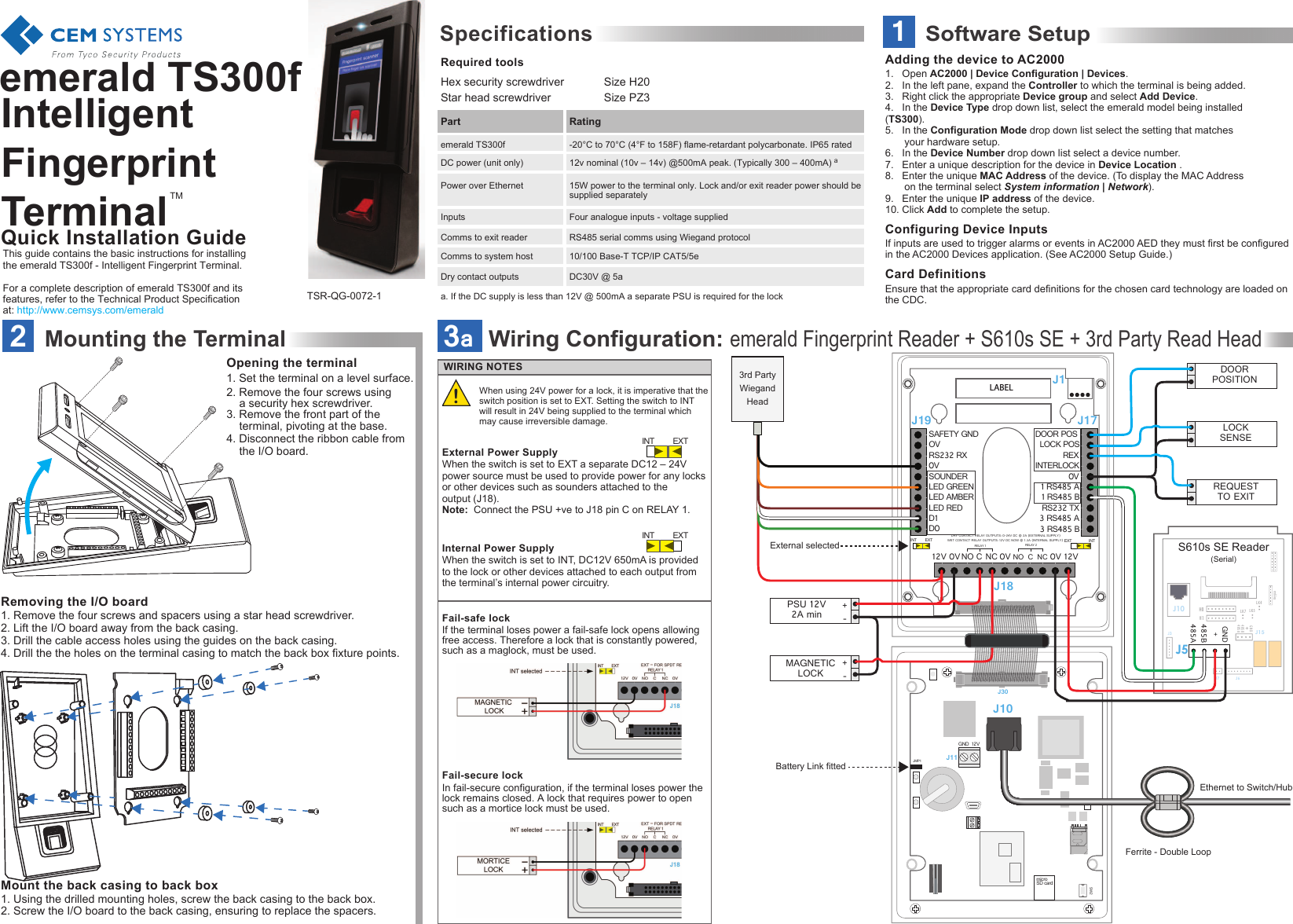
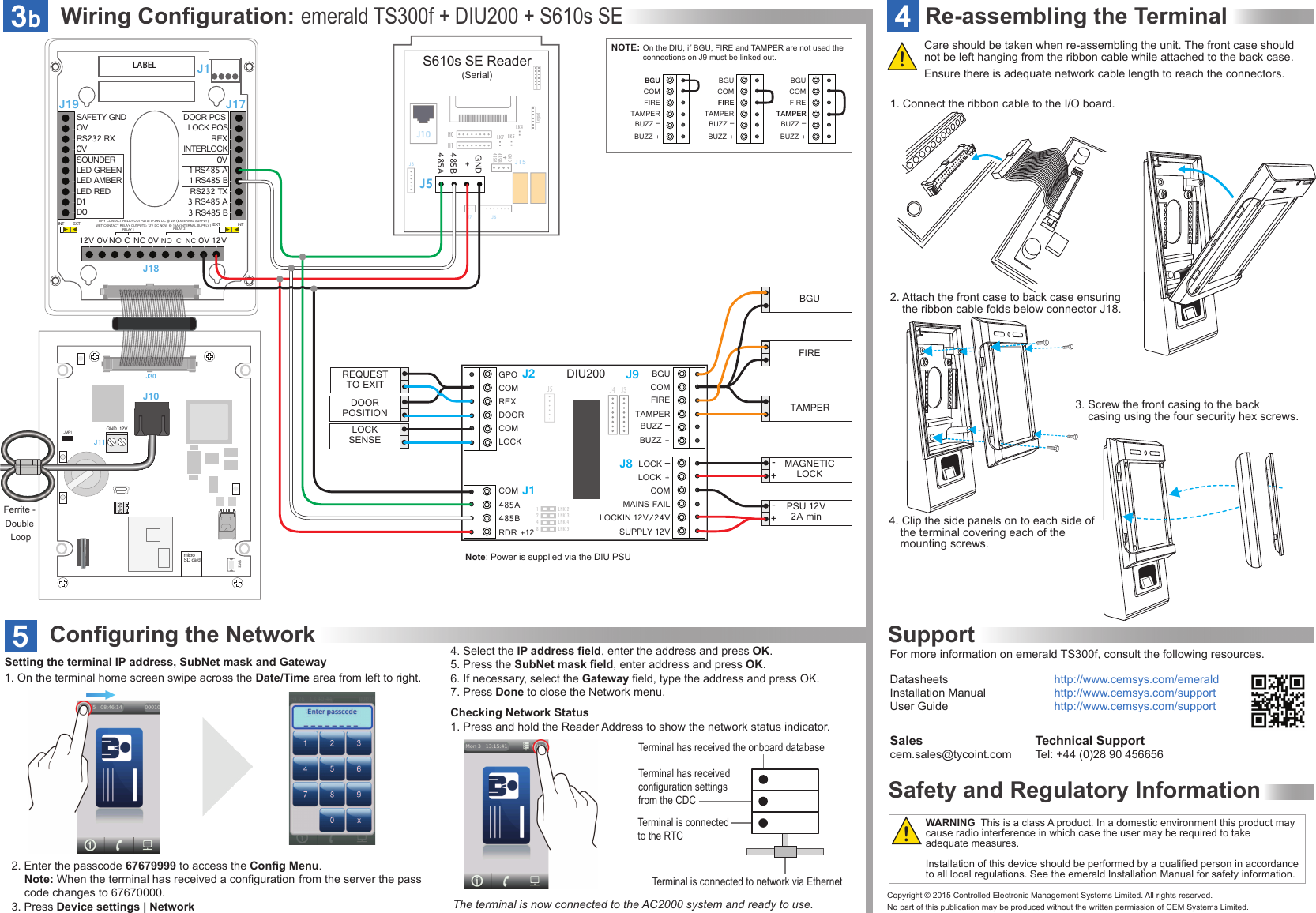
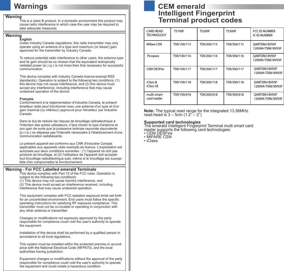
Controlled Electronic Management Systems TSR618V93F Emerald Intelligent Fingerprint Terminal User Manual 15 Emerald Fingerprint Quick Guide

Controlled Electronic Management Systems Ltd Emerald Intelligent Fingerprint Terminal 15 Emerald Fingerprint Quick Guide

Users Manual

Quick Installation Guide1Software SetupTMemerald TS300f Intelligent Fingerprint TerminalRequired toolsSpecificationsHex security screwdriver  Size H20Star head screwdriver     Size PZ3-20°C to 70°C (4°F to 158F) flame-retardant polycarbonate. IP65 rated15W power to the terminal only. Lock and/or exit reader power should be supplied separatelyThis guide contains the basic instructions for installing the emerald TS300f - Intelligent Fingerprint Terminal.For a complete description of emerald TS300f and its features, refer to the Technical Product Specification at: http://www.cemsys.com/emerald12v nominal (10v – 14v) @500mA peak. (Typically 300 – 400mA) aFour analogue inputs - voltage suppliedRS485 serial comms using Wiegand protocol10/100 Base-T TCP/IP CAT5/5eDC30V @ 5aDry contact outputsComms to system hostComms to exit readerInputsa. If the DC supply is less than 12V @ 500mA a separate PSU is required for the lockPower over EthernetDC power (unit only)emerald TS300fPart RatingTSR-QG-0072-11.   Open AC2000 | Device Configuration | Devices.2.   In the left pane, expand the Controller to which the terminal is being added.3.   Right click the appropriate Device group and select Add Device.4.   In the Device Type drop down list, select the emerald model being installed      (TS300). 5.   In the Configuration Mode drop down list select the setting that matches  your hardware setup.6.   In the Device Number drop down list select a device number. 7.   Enter a unique description for the device in Device Location .8.   Enter the unique MAC Address of the device. (To display the MAC Address   on the terminal select System information | Network).9.   Enter the unique IP address of the device.10. Click Add to complete the setup.If inputs are used to trigger alarms or events in AC2000 AED they must first be configured in the AC2000 Devices application. (See AC2000 Setup Guide.)Ensure that the appropriate card definitions for the chosen card technology are loaded on the CDC.Adding the device to AC2000Configuring Device InputsCard DefinitionsWiring Configuration: emerald Fingerprint Reader + S610s SE + 3rd Party Read Head3a-+PSU 12V2A minJ30JMP1SW212VGNDJ10J11SAFETY GND OVRS232 RXSOUNDERLED GREENLED AMBER0VLED REDD0 INT  EXT INT EXTDRY CONTACT RELAY OUTPUTS: 0-24V DC @ 2A (EXTERNAL SUPPLY)WET CONTACT RELAY OUTPUTS: 12V DC NOW @ 1.3A (INTERNAL SUPPLY) D1  DOOR POS REX1 RS485 A1 RS485 BRS232 TX0V3 RS485 A3 RS485 B12V 12V0V NORELAY 1CCNCNC0V 0VNOINTERLOCKLOCK POSRELAY 2J19 J17J18External selectedBattery Link fittedEthernet to Switch/HubLK5LK4LK7S610s SE Reader(Serial)H0J5J15H1485A485 BGNDJ6J7J3J10Keypad485A485BGND+DOORPOSITION-+MAGNETICLOCKLOCKSENSEREQUESTTO EXIT 3rd Party Wiegand HeadJ1LABELFerrite - Double Loopmicro SD cardIn fail-secure configuration, if the terminal loses power the lock remains closed. A lock that requires power to open such as a mortice lock must be used.WIRING NOTESIf the terminal loses power a fail-safe lock opens allowing free access. Therefore a lock that is constantly powered, such as a maglock, must be used.Fail-safe lock Internal Power SupplyExternal Power SupplyFail-secure lock INT  EXTINT  EXTWhen using 24V power for a lock, it is imperative that the switch position is set to EXT. Setting the switch to INT will result in 24V being supplied to the terminal which may cause irreversible damage.When the switch is set to EXT a separate DC12 – 24V  power source must be used to provide power for any locks or other devices such as sounders attached to the output (J18).Note:  Connect the PSU +ve to J18 pin C on RELAY 1.When the switch is set to INT, DC12V 650mA is provided to the lock or other devices attached to each output from the terminal’s internal power circuitry.2Mounting the Terminal1. Remove the four screws and spacers using a star head screwdriver.2. Lift the I/O board away from the back casing.3. Drill the cable access holes using the guides on the back casing.4. Drill the the holes on the terminal casing to match the back box fixture points.Opening the terminal1. Set the terminal on a level surface.2. Remove the four screws using    a security hex screwdriver.3. Remove the front part of the      terminal, pivoting at the base. 4. Disconnect the ribbon cable from   the I/O board.Mount the back casing to back box 1. Using the drilled mounting holes, screw the back casing to the back box.2. Screw the I/O board to the back casing, ensuring to replace the spacers.Removing the I/O board !
Wiring Configuration: emerald TS300f + DIU200 + S610s SE3bLK5LK4LK7S610s SE Reader(Serial)H0J5J15H1485 A485BGNDJ6J7J3J10Keypad485A485BGND+LNK 2 LNK 3 LNK 4LNK 51248J1J5GPOCOMREXDOORCOMLOCKJ9J8BGUCOMFIRETAMPERBUZZ –BUZZ +COM485A 485B RDR +12J2LOCK –COMMAINS FAILLOCKIN 12V/24VSUPPLY 12VLOCK +J4J3DIU200J30JMP1SW212VGNDJ10J11SAFETY GNDOVRS232 RXSOUNDERLED GREENLED AMBER0VLED REDD0 INT  EXT INT EXTDRY CONTACT RELAY OUTPUTS: 0-24V DC @ 2A (EXTERNAL SUPPLY)WET CONTACT RELAY OUTPUTS: 12V DC NOW @ 13A (INTERNAL SUPPLY) D1  DOOR POS REX1 RS485 A1 RS485 BRS232 TX0V3 RS485 A3 RS485 B12V 12V0V NORELAY 1CCNCNC0V 0VNOINTERLOCKLOCK POSRELAY 2J19 J17J18DOORPOSITIONLOCKSENSEREQUESTTO EXITNOTE: On the DIU, if BGU, FIRE and TAMPER are not used the connections on J9 must be linked out.BGUCOMFIRETAMPERBUZZ –BUZZ +BGUCOMFIRETAMPERBUZZ –BUZZ +BGUCOMFIRETAMPERBUZZ –BUZZ +FIREBGUTAMPERMAGNETICLOCK-+PSU 12V2A min-+J1LABELFerrite - Double Loopmicro SD cardFor more information on emerald TS300f, consult the following resources.Datasheets      http://www.cemsys.com/emeraldInstallation Manual    http://www.cemsys.com/supportUser Guide      http://www.cemsys.com/supportTechnical SupportTel: +44 (0)28 90 456656 Salescem.sales@tycoint.com1. On the terminal home screen swipe across the Date/Time area from left to right.Setting the terminal IP address, SubNet mask and GatewayChecking Network Status1. Press and hold the Reader Address to show the network status indicator.Terminal has received the onboard database Terminal has received configuration settings from the CDCTerminal is connected to network via EthernetTerminal is connected to the RTCConfiguring the Network5The terminal is now connected to the AC2000 system and ready to use.4. Select the IP address field, enter the address and press OK.5. Press the SubNet mask field, enter address and press OK.6. If necessary, select the Gateway field, type the address and press OK.7. Press Done to close the Network menu.!!WARNING  This is a class A product. In a domestic environment this product may cause radio interference in which case the user may be required to take adequate measures.Installation of this device should be performed by a qualified person in accordance to all local regulations. See the emerald Installation Manual for safety information.2. Enter the passcode 67679999 to access the Config Menu.  Note: When the terminal has received a configuration  from the server the pass    code changes to 67670000.3. Press Device settings | NetworkSafety and Regulatory InformationSupportCopyright © 2015 Controlled Electronic Management Systems Limited. All rights reserved.No part of this publication may be produced without the written permission of CEM Systems Limited.4Re-assembling the TerminalEnsure there is adequate network cable length to reach the connectors.Care should be taken when re-assembling the unit. The front case should not be left hanging from the ribbon cable while attached to the back case.1. Connect the ribbon cable to the I/O board.Note: Power is supplied via the DIU PSU3. Screw the front casing to the back      casing using the four security hex screws.4. Clip the side panels on to each side of    the terminal covering each of the      mounting screws.2. Attach the front case to back case ensuring   the ribbon cable folds below connector J18.
CEM emeraldTerminal product codesIntelligent FingerprintWarningsWarning This is a class B product. In a domestic environment this product may cause radio interference in which case the user may be required to take adequate measuresWarning EnglishUnder Industry Canada regulations, this radio transmitter may only operate using an antenna of a type and maximum (or lesser) gain approved for the transmitter by Industry Canada.To reduce potential radio interference to other users, the antenna type and its gain should be so chosen that the equivalent isotropically radiated power (e.i.r.p.) is not more than that necessary for successful communication.This device complies with Industry Canada licence-exempt RSS standard(s). Operation is subject to the following two conditions: (1) this device may not cause interference, and (2) this device must accept any interference, including interference that may cause undesired operation of the device.FrançaisConformément à la réglementation d'Industrie Canada, le présent émetteur radio peut fonctionner avec une antenne d'un type et d'un gain maximal (ou inférieur) approuvé pour l'émetteur par Industrie Canada.Dans le but de réduire les risques de brouillage radioélectrique à l'intention des autres utilisateurs, il faut choisir le type d'antenne et son gain de sorte que la puissance isotrope rayonnée équivalente (p.i.r.e.) ne dépasse pas l'intensité nécessaire à l'établissement d'une communication satisfaisante.Le présent appareil est conforme aux CNR d'Industrie Canada applicables aux appareils radio exempts de licence. L'exploitation est autorisée aux deux conditions suivantes : (1) l'appareil ne doit pas produire de brouillage, et (2) l'utilisateur de l'appareil doit accepter tout brouillage radioélectrique subi, même si le brouillage est suscep-tible d'en compromettre le fonctionnement.Warning - For FCC Labelled emerald TerminalsThis device complies with Part 15 of the FCC rules. Operation is subject to the following two conditions:(1) This device may not cause harmful interference, and(2) This device must accept an interference received, including interference that may cause undesired operation.This equipment complies with FCC radiation exposure limits set forth for an uncontrolled environment. End users must follow the specific operating instructions for satisfying RF exposure compliance. This transmitter must not be co-located or operating in conjunction with any other antenna or transmitter.Changes or modifications not expressly approved by the party responsible for compliance could void the user's authority to operate the equipment.Installation of this device shall be performed by a qualified person in accordance to all local regulations.This system must be installed within the protected premise in accord-ance with the National Electrical Code (NFPA70), and the local authorities having jurisdiction.Equipment changes or modifications without the approval of the party responsible for compliance could void the user's authority to operate the equipment and could create a hazardous condition.CARD READ TECHNOLOGYTS100F TS200F TS300F FCC ID NUMBERIC ID NUMBERMifare CSN TSR/100/115PicopassCEM DESFireiClass & iClass SEmulti smart card readerTSR/100/116TSR/100/117TSR/100/118TSR/100/618TSR/200/115 TSR/300/115TSR/200/116 TSR/300/116TSR/200/117 TSR/300/117TSR/200/118 TSR/300/118TSR/200/618 TSR/300/618QABTSR618V93F12009A-TSR618V93FQABTSR618V93F12009A-TSR618V93FQABTSR618V93F12009A-TSR618V93FQABTSR618V93F12009A-TSR618V93FQABTSR618V93F12009A-TSR618V93FNote: The typical read range for the integrated 13.56MHz read-head is 3 – 5cm (1.2” – 2”)Supported card technologies The emerald Intelligent Fingerprint Terminal multi smart card reader supports the following card technologies:• CEM DESFire• MIFARE CSN • iClass

Navigation menu