Controlled Electronic Management Systems S700PXV1-00 S700 multi smart card reader User Manual S700 Quick Guide
Controlled Electronic Management Systems Ltd S700 multi smart card reader S700 Quick Guide
Contents
- 1. User Manual
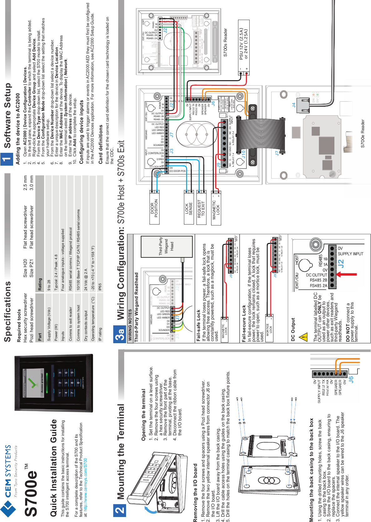
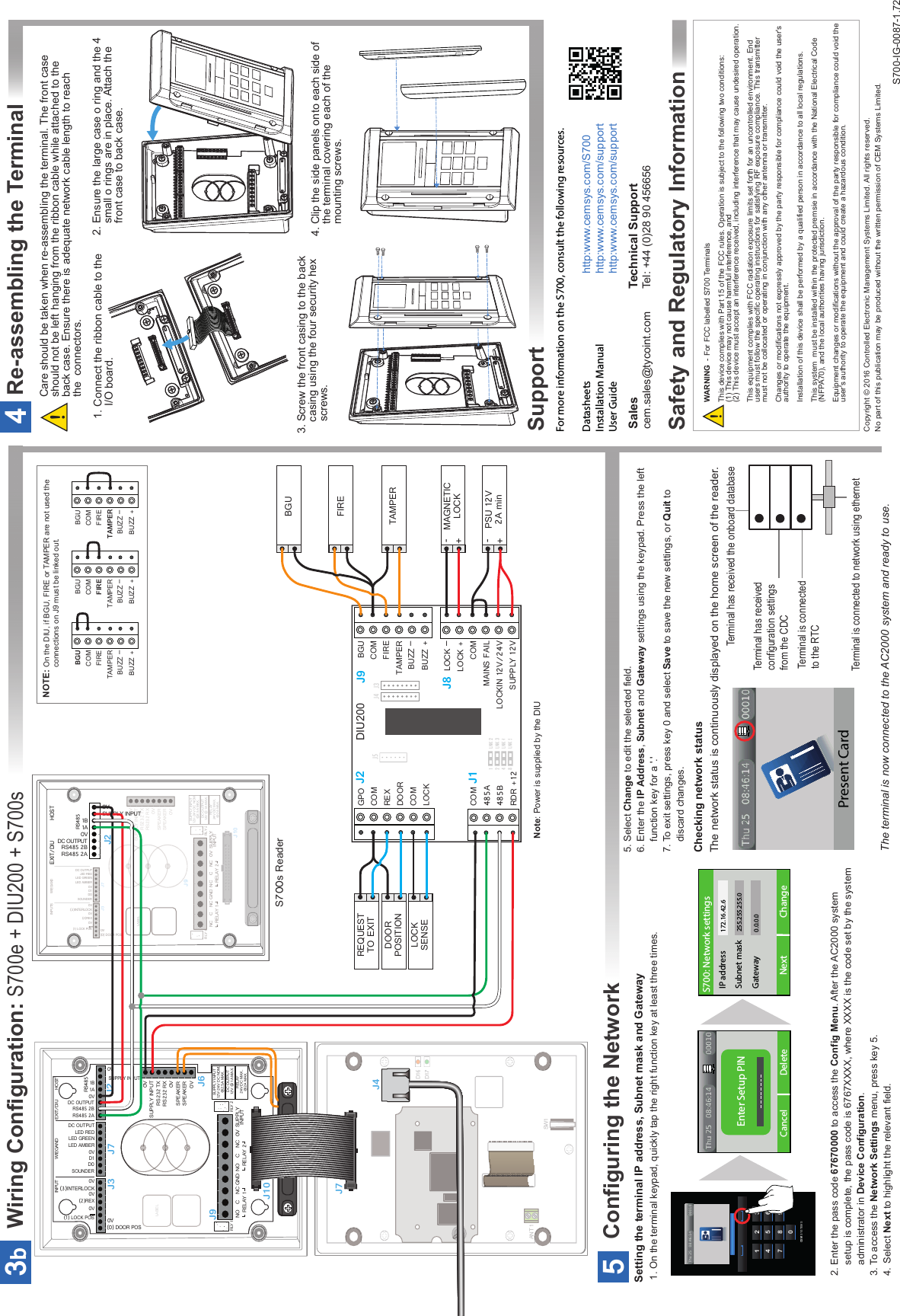
- 2. Quick start guide
Quick start guide