Controlled Electronic Management Systems INFOPROX Proximity Card Reader User Manual 14 The Transaction Reports Option
Controlled Electronic Management Systems Ltd Proximity Card Reader 14 The Transaction Reports Option
UserManual.wiki
>
Controlled Electronic Management Systems
>
INFOPROX User Manual
Users Manual
Navigation menu
Upload a User Manual
Namespaces
Wiki Guide
HTML
PDF
Info
Views
User Manual
Discussion / Help
Navigation
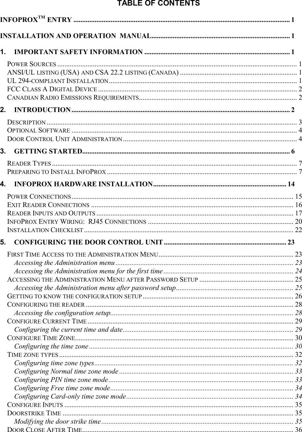

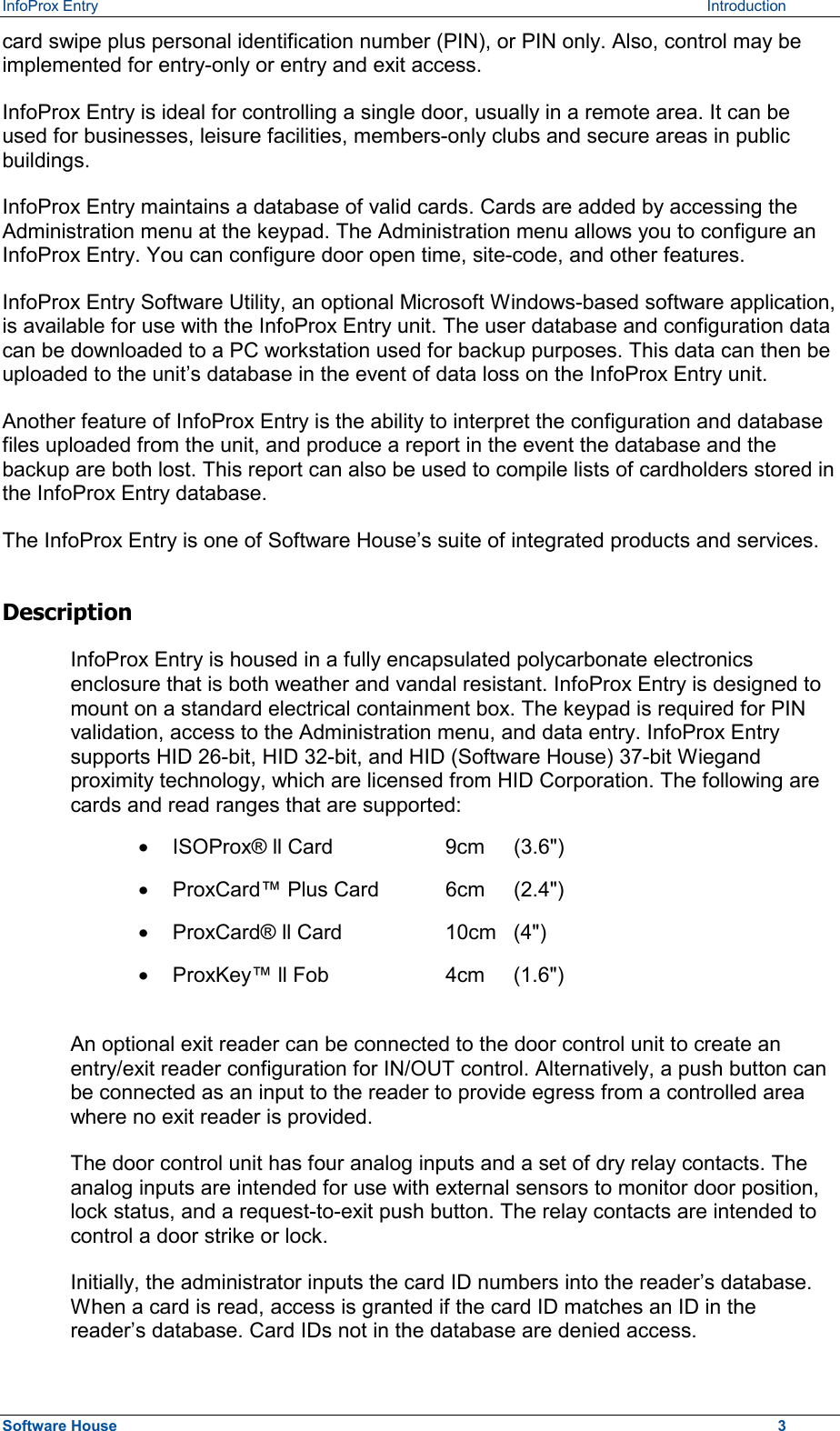
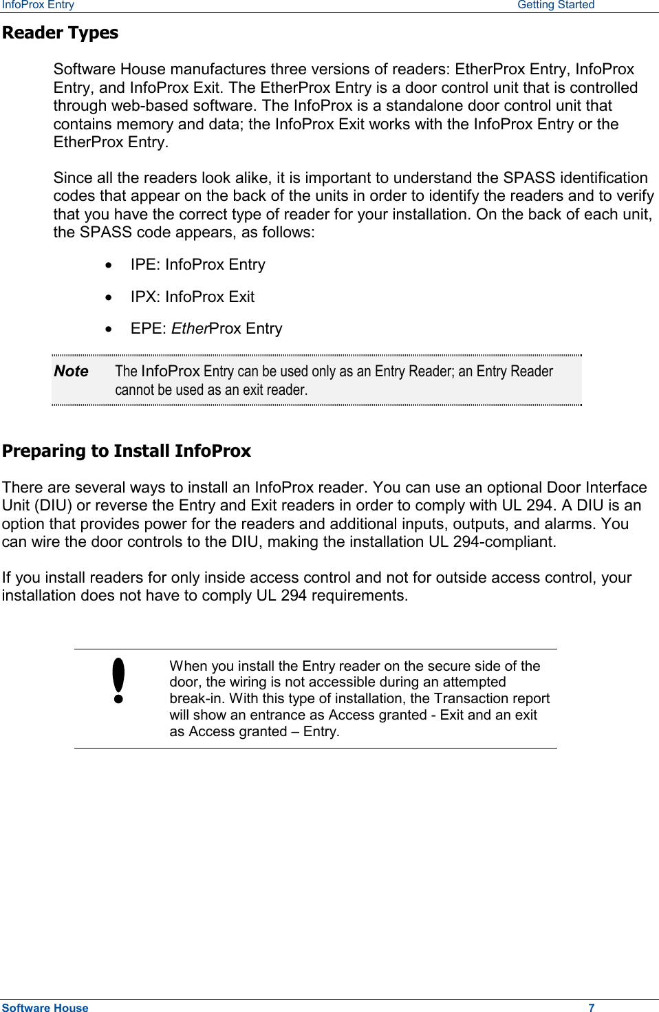
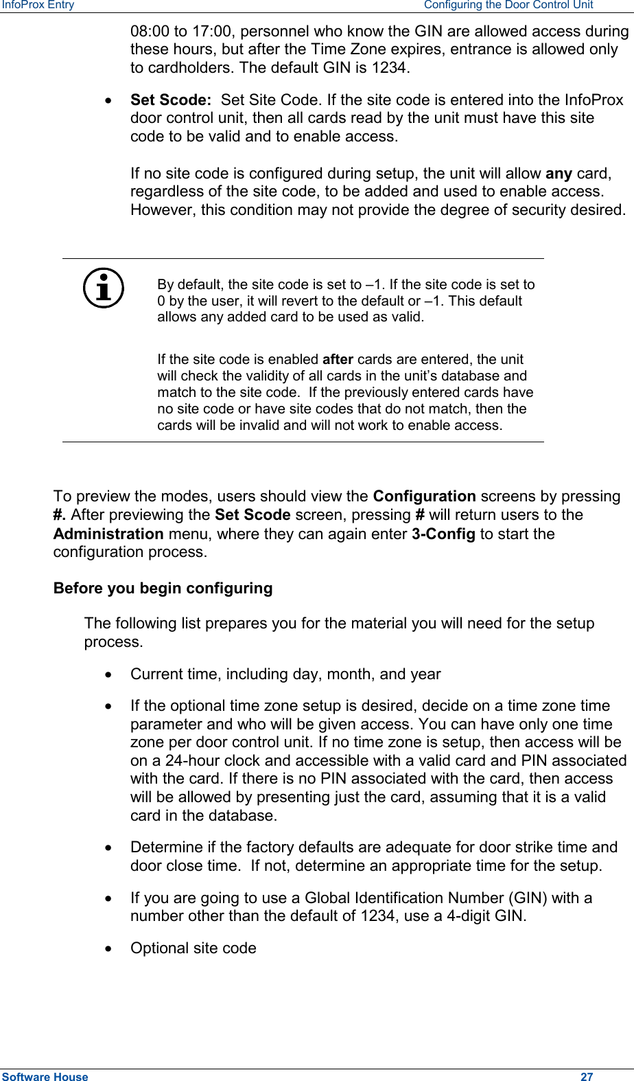
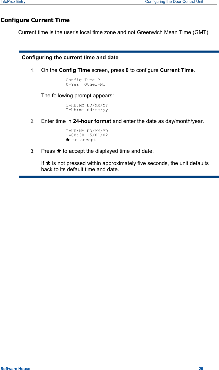
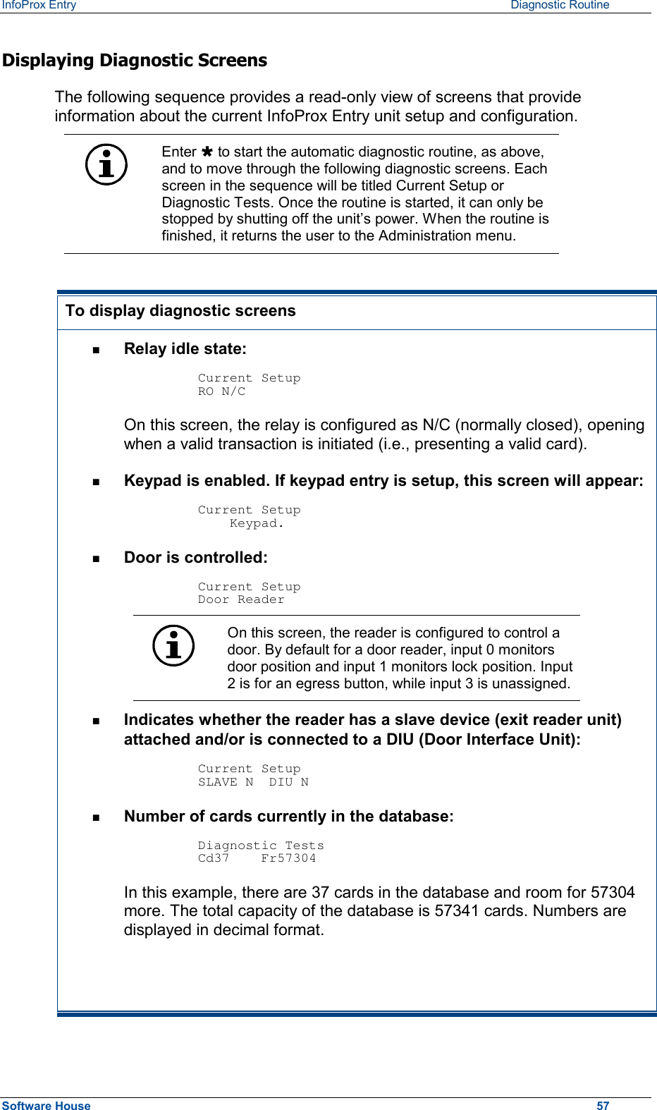
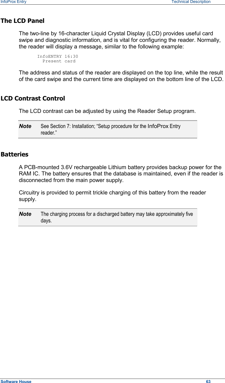
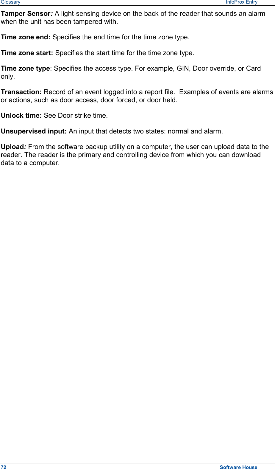
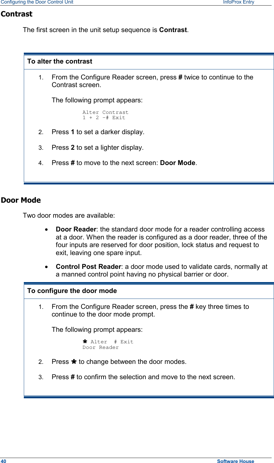
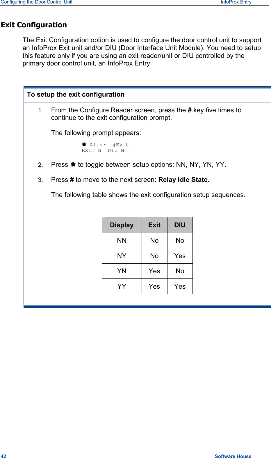
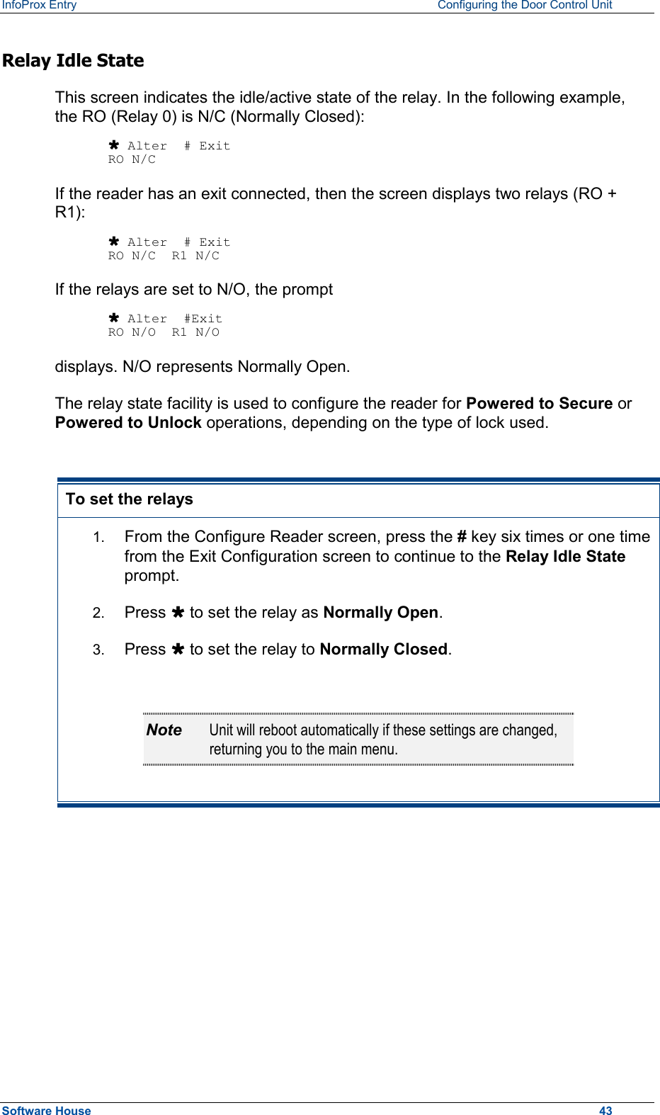
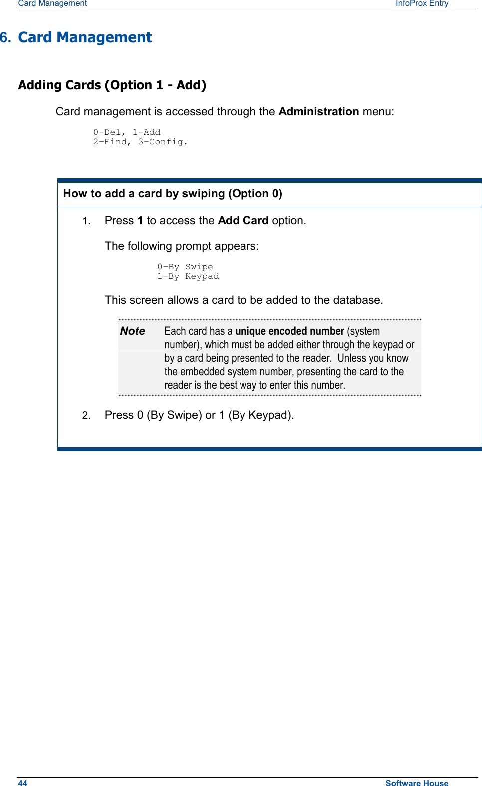
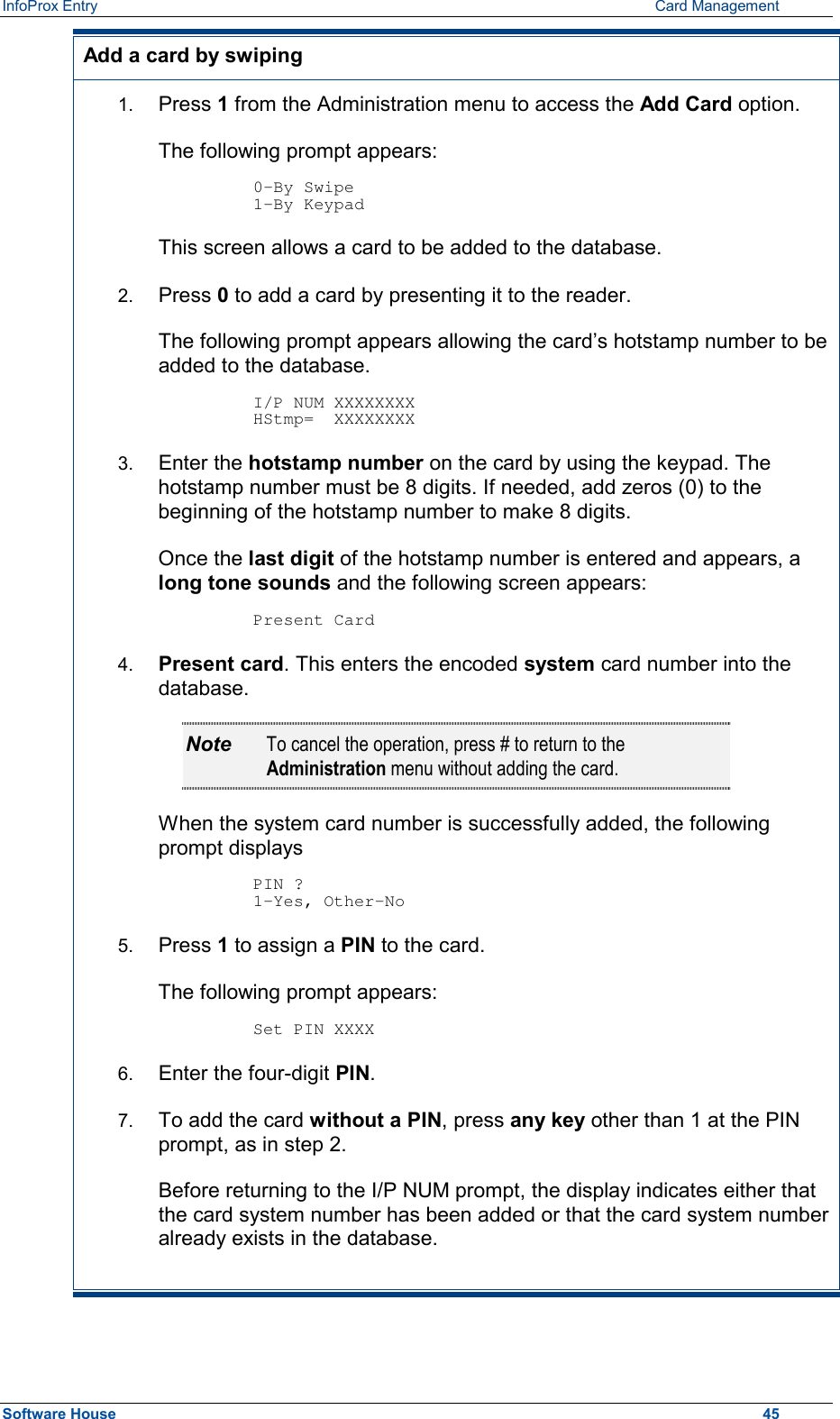
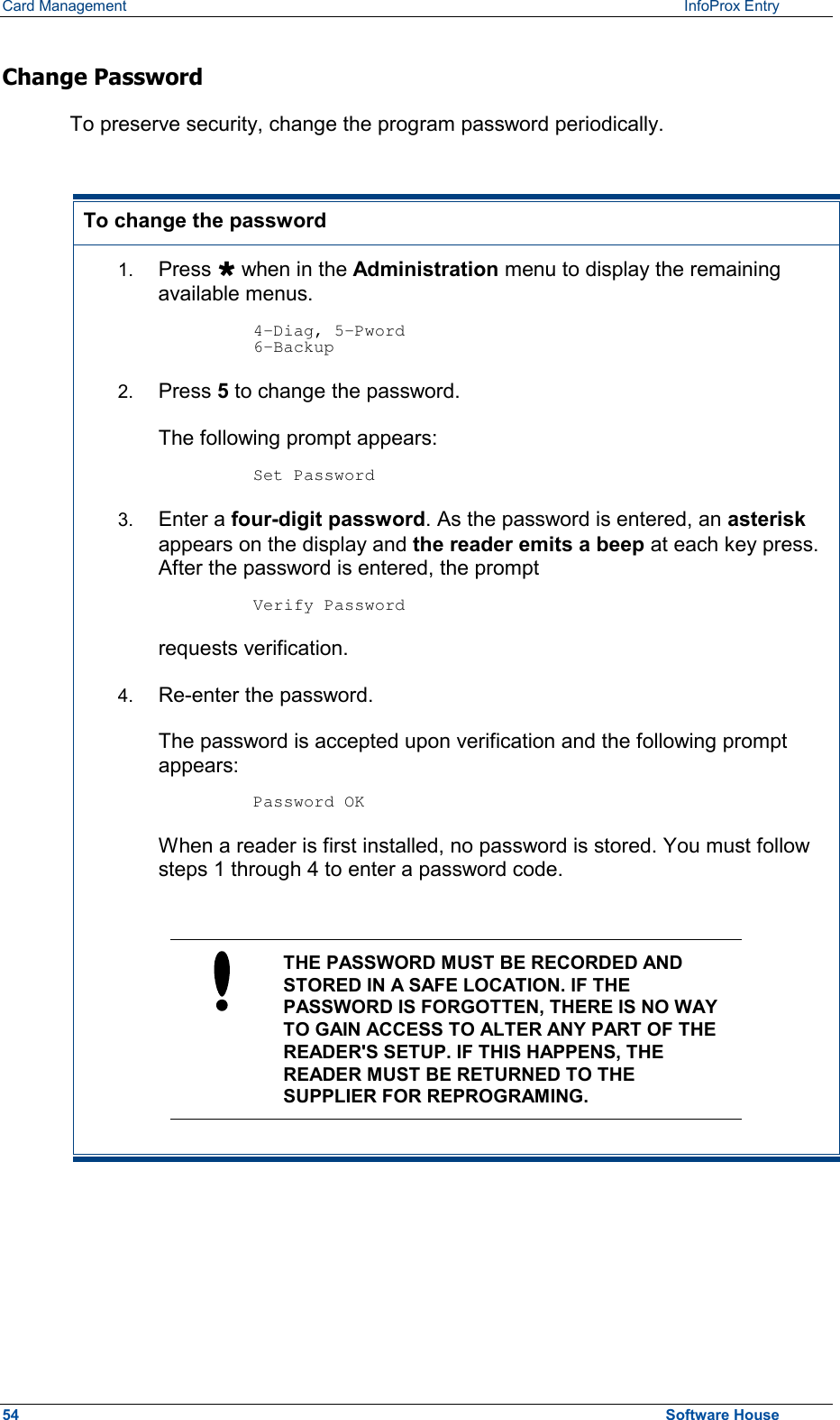
![InfoProx Entry Configuring the Door Control Unit Door Control Unit Diagnostic Screen Set Up Once the site code is entered, the second stage of the door control unit setup must be completed so that the unit conforms to a user’s needs. This part of the setup is accessed through the Diagnostic screen. Accessing the diagnostic screen setup 1. Press Ù to display the second screen of the Administration menu. 2. Press 4. The following screen appears. Diagnostic Tests [S/N xxxx] This screen is automatically followed by the Configure Rdr ? screen: Configure Rdr ? No Ù Yes # The Configure Reader screen is the doorway to unit setup, which requires user interaction. All other screens under the Diagnostic screen category are read-only and do not require user interaction. If you do not press Yes-# within five seconds or if you press Ù, the read-only diagnostic screens display in sequence. Once this sequence begins, you can stop it only by unplugging the unit. The diagnostic sequence will return you to the Administration menu when completed. Each diagnostic screen will display for the default time of five seconds. 3. Press # to enter the unit setup mode. The following prompt appears: RDR Setup Option # to continue 4. Press # to continue with unit setup. The following series of reader unit setup screens appears: Contrast, Door Mode, Keypad Enable/Disable, Exit Configuration, and Relay Idle State. Software House 39](https://usermanual.wiki/Controlled-Electronic-Management-Systems/INFOPROX/User-Guide-237904-Page-45.png)
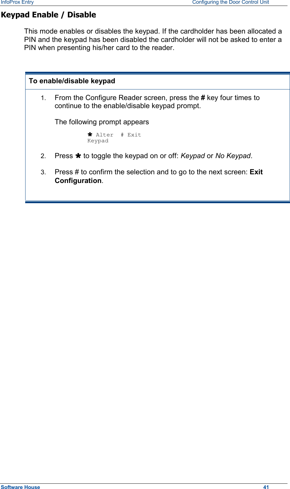
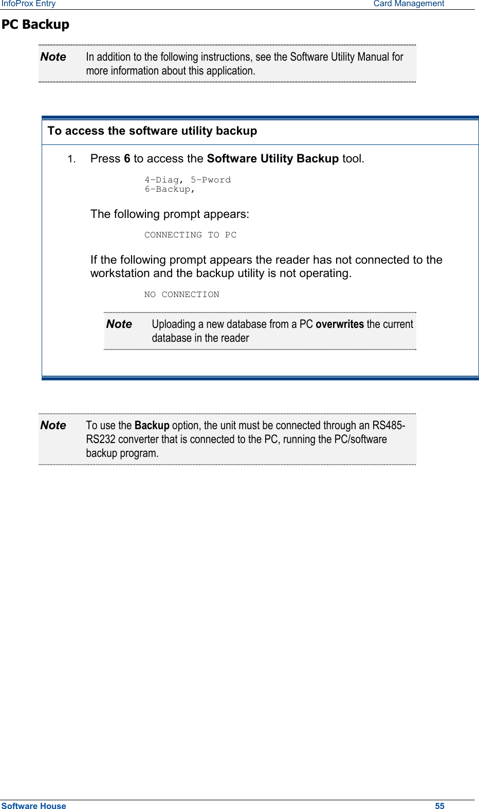
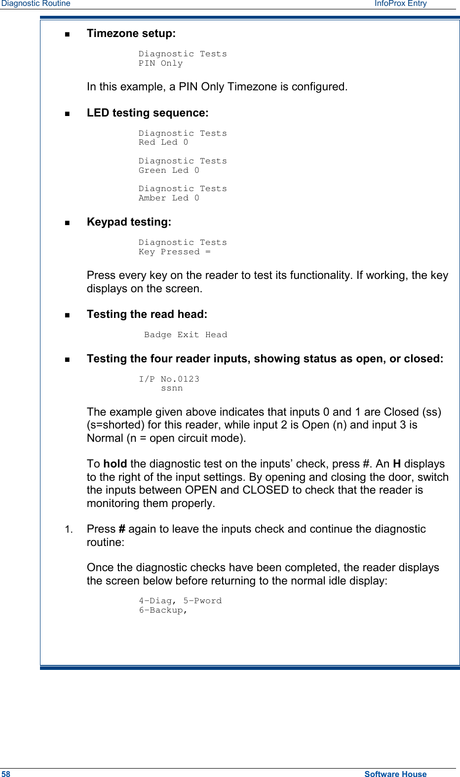
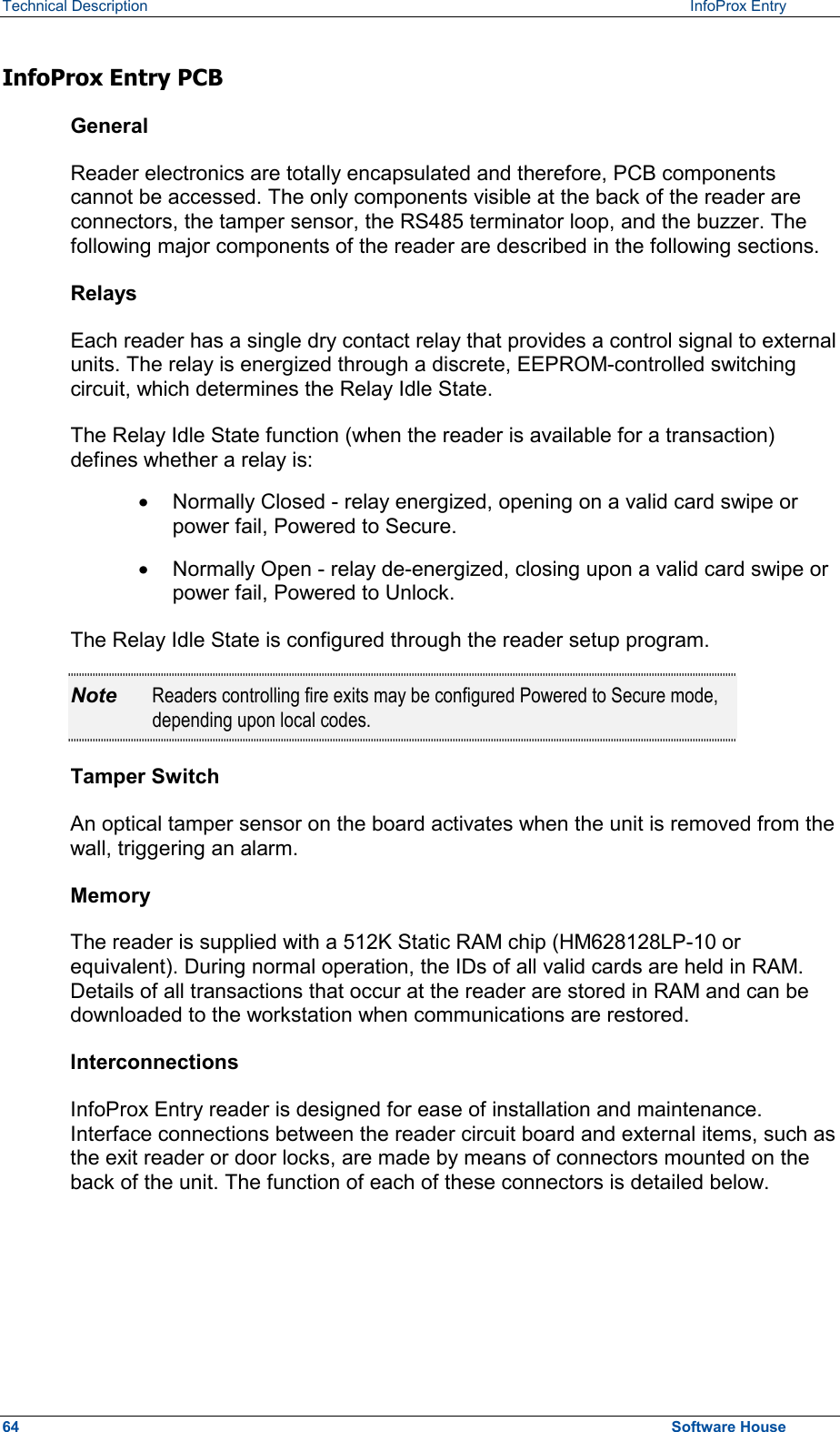
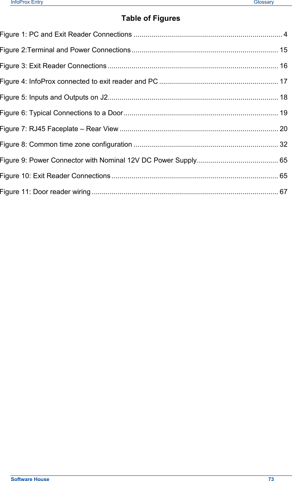
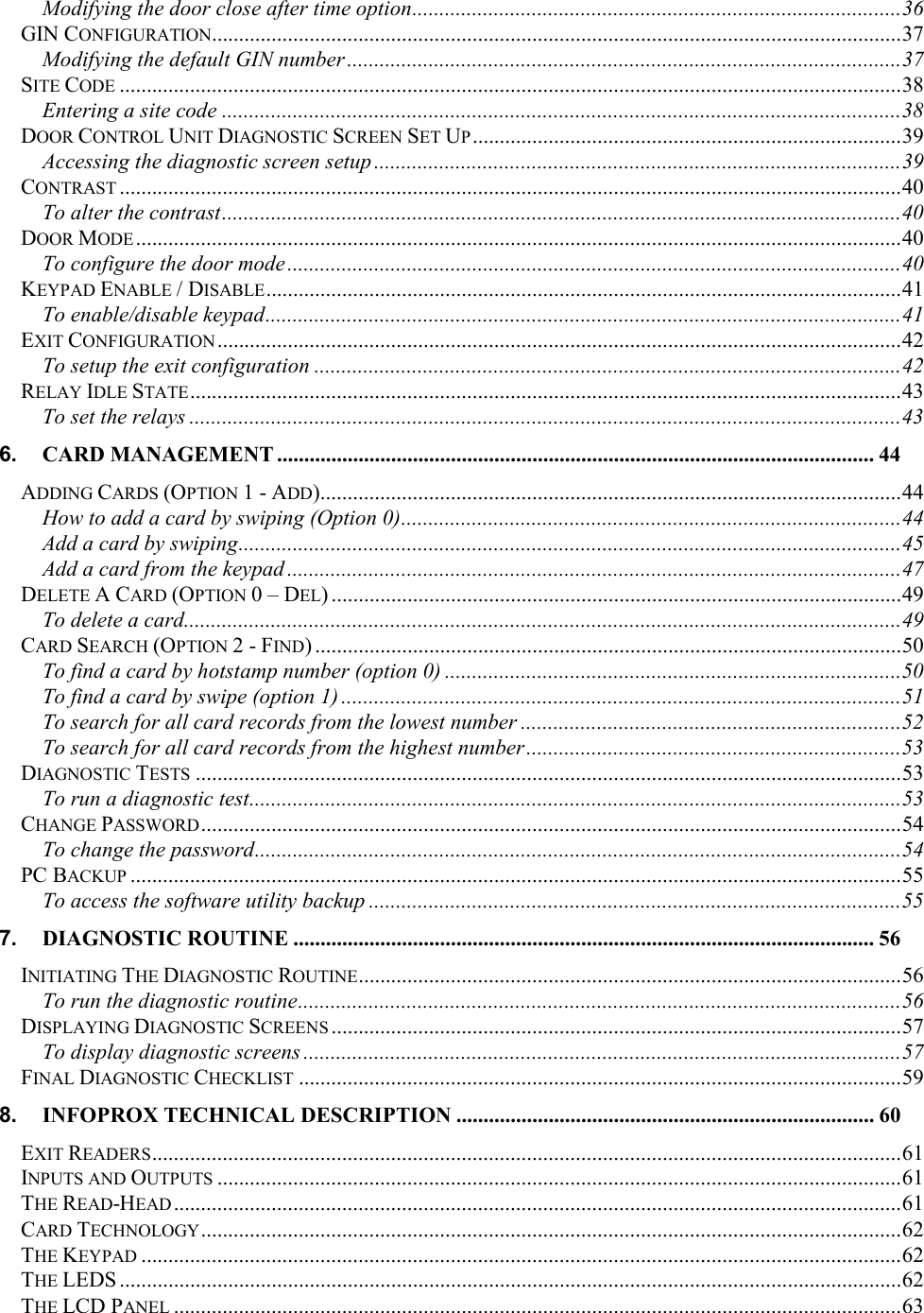
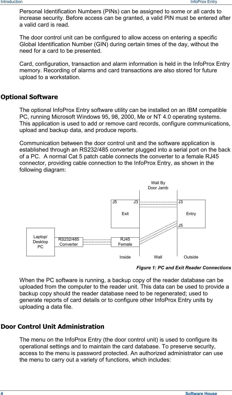
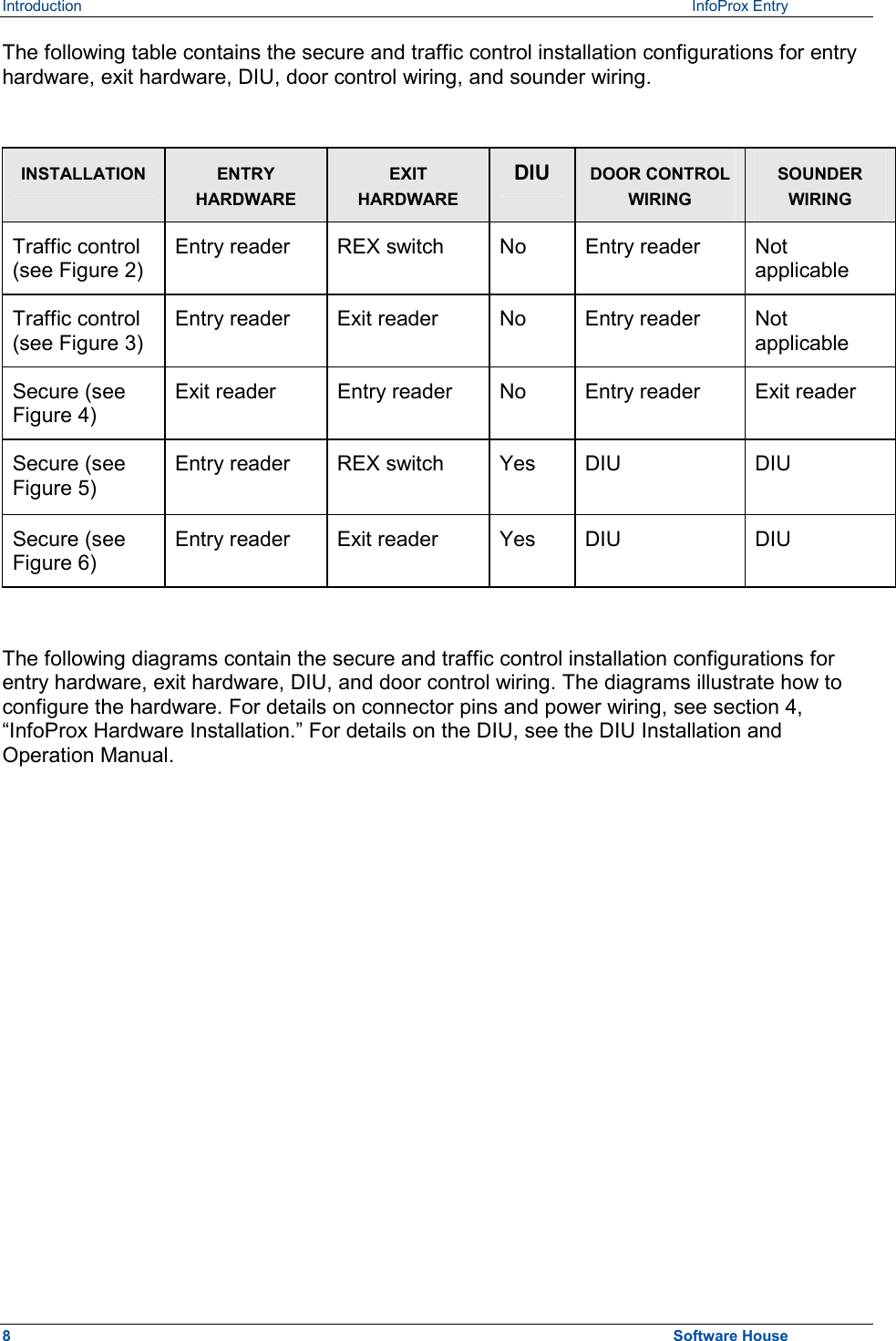
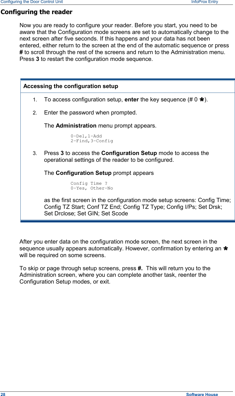
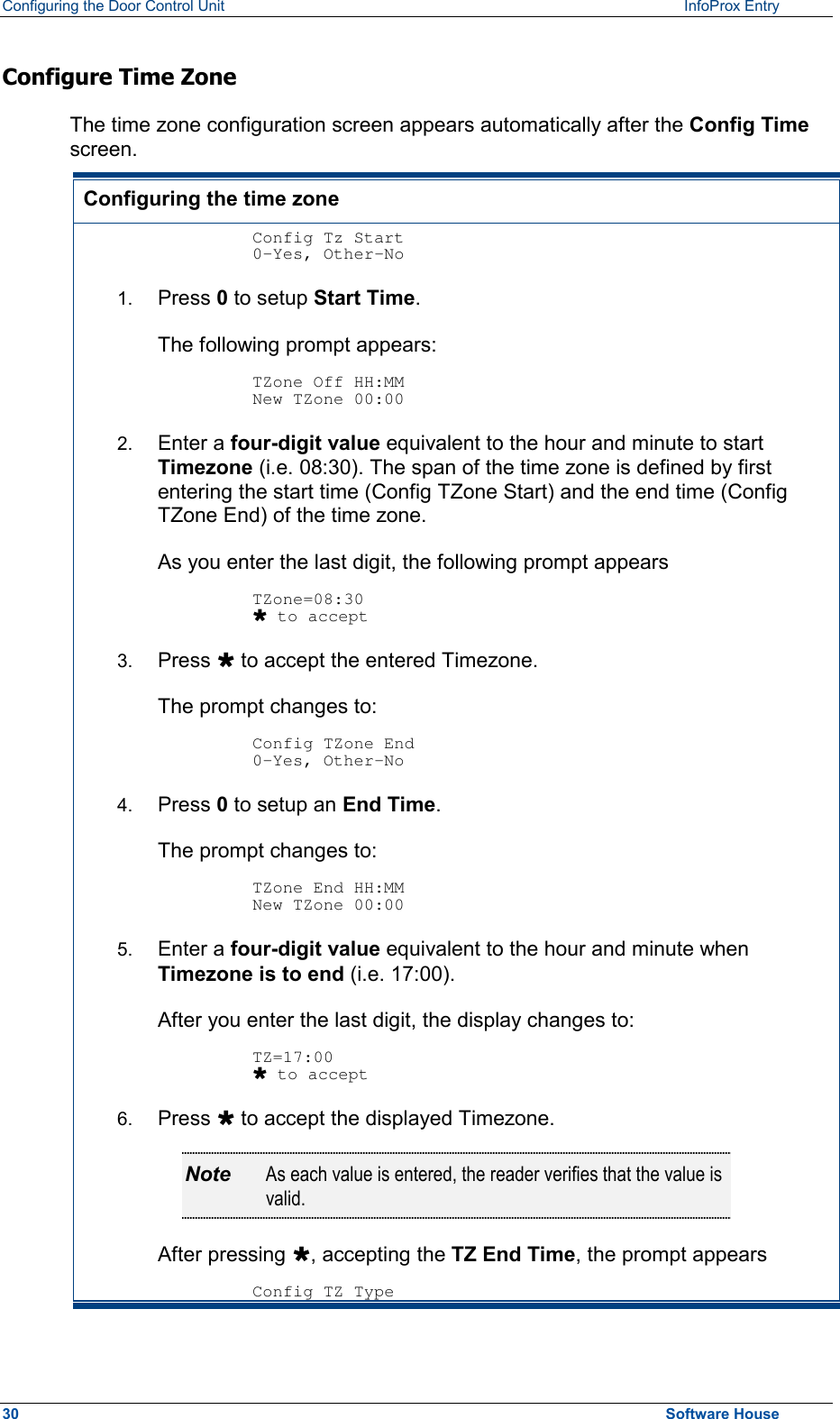
![Diagnostic Routine InfoProx Entry 7. DIAGNOSTIC ROUTINE Once the InfoProx Entry reader has been set up and configured, check the current setup status and operational functions of the reader by starting the diagnostic routine. The diagnostic routine menu also allows you to change the reader setup, as was explained in section 4. Initiating The Diagnostic Routine To run the diagnostic routine 1. Enter (# 0 Ù), the administration key sequence. 2. Enter the password. The following screen appears. O-Del, 1-Add 2-Find, 3-Config 3. Press Ù to open the second setup screen. 4-Diag, 2-Pword 6-Backup, 4. Press 4 to open the following screen. InfoProx ENTRY [Build 0.155] Note The first part of the diagnostic routine is automatic and will test the reader's functionality. There are several screens that will appear and then end with the following screen. Configure Rdr ? No Ù Yes # 5. Press Ù to start the diagnostic routine. The display scrolls through the various screens. By pressing #, the user enters the reader setup mode, as shown in section 5. If setup has already been done, then bypass this mode by pressing Ù to enter the read-only diagnostic sequence. 56 Software House](https://usermanual.wiki/Controlled-Electronic-Management-Systems/INFOPROX/User-Guide-237904-Page-62.png)