Comtrend VR3063U Home Gateway User Manual CT 5374
Comtrend Corporation Home Gateway CT 5374
UserManual.wiki
>
Comtrend
>
VR3063U User Manual
>
User Manual III
Contents
1.
User Manual I
2.
User Manual II
3.
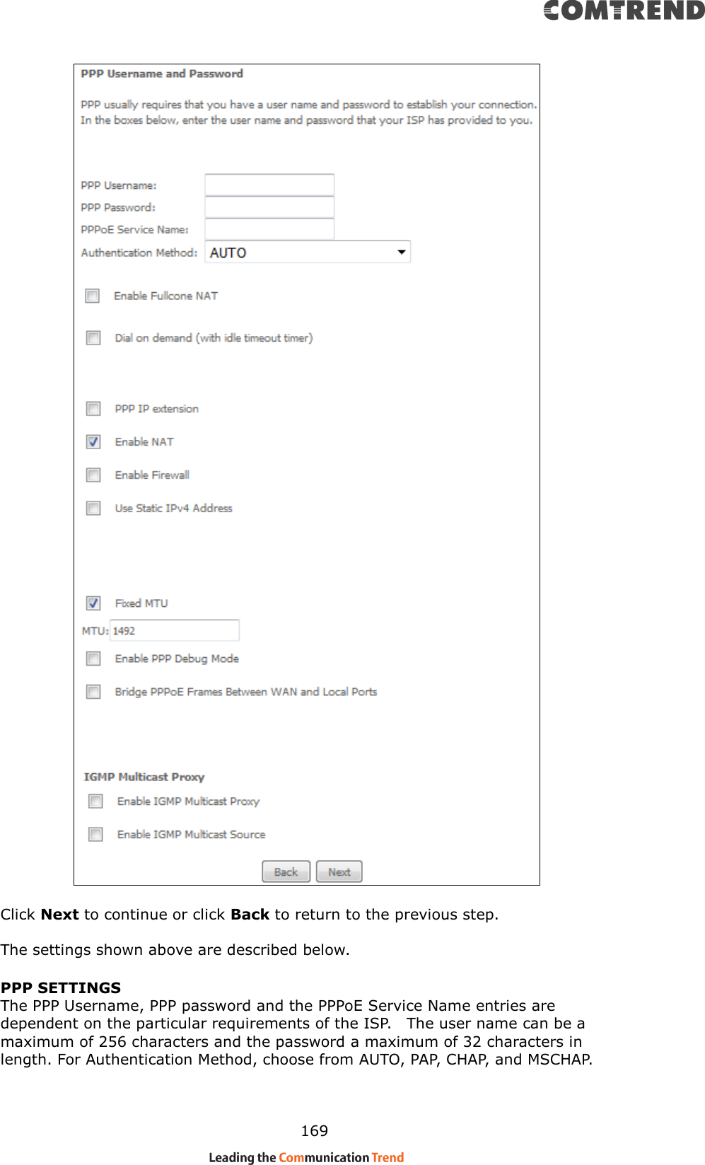
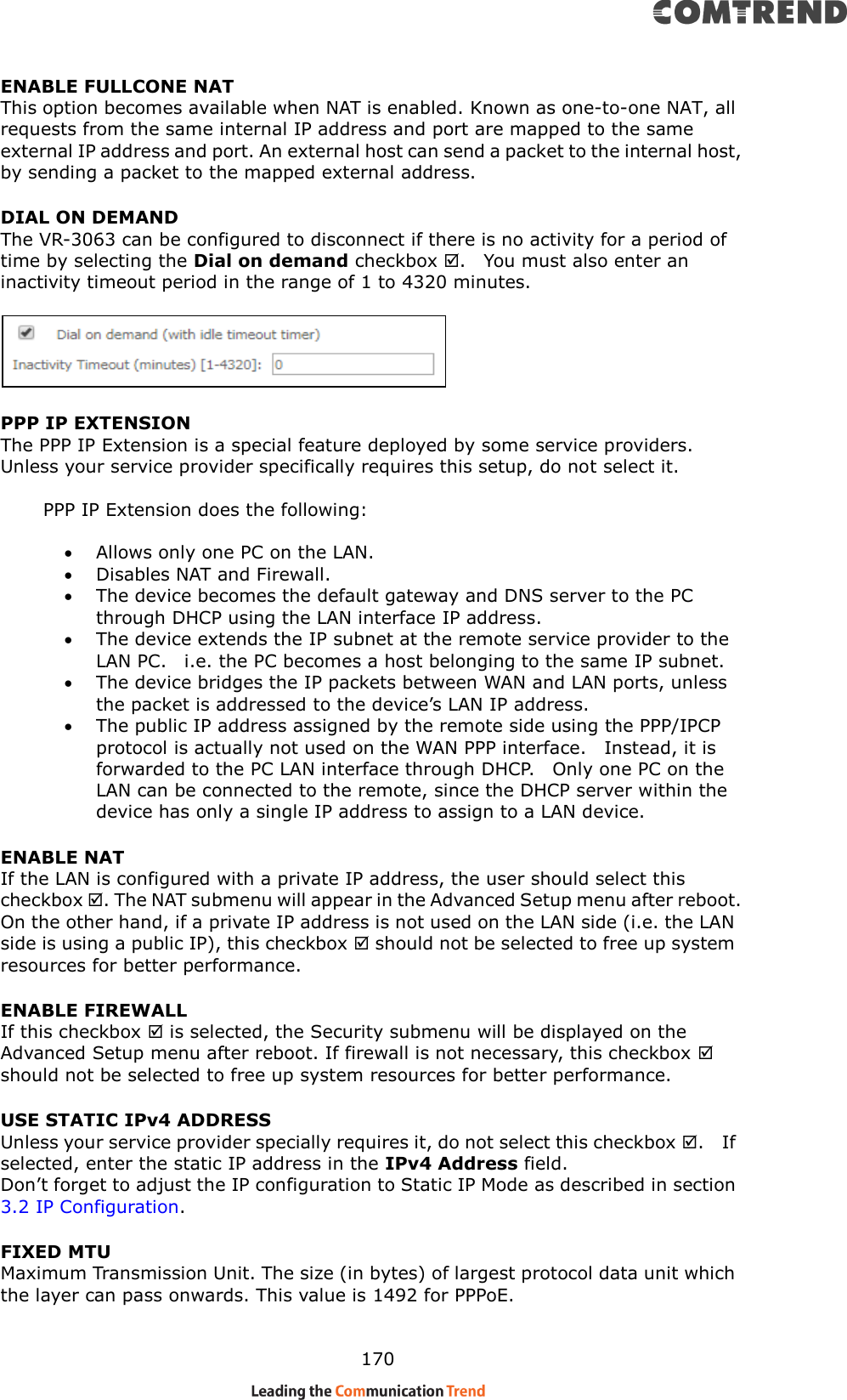
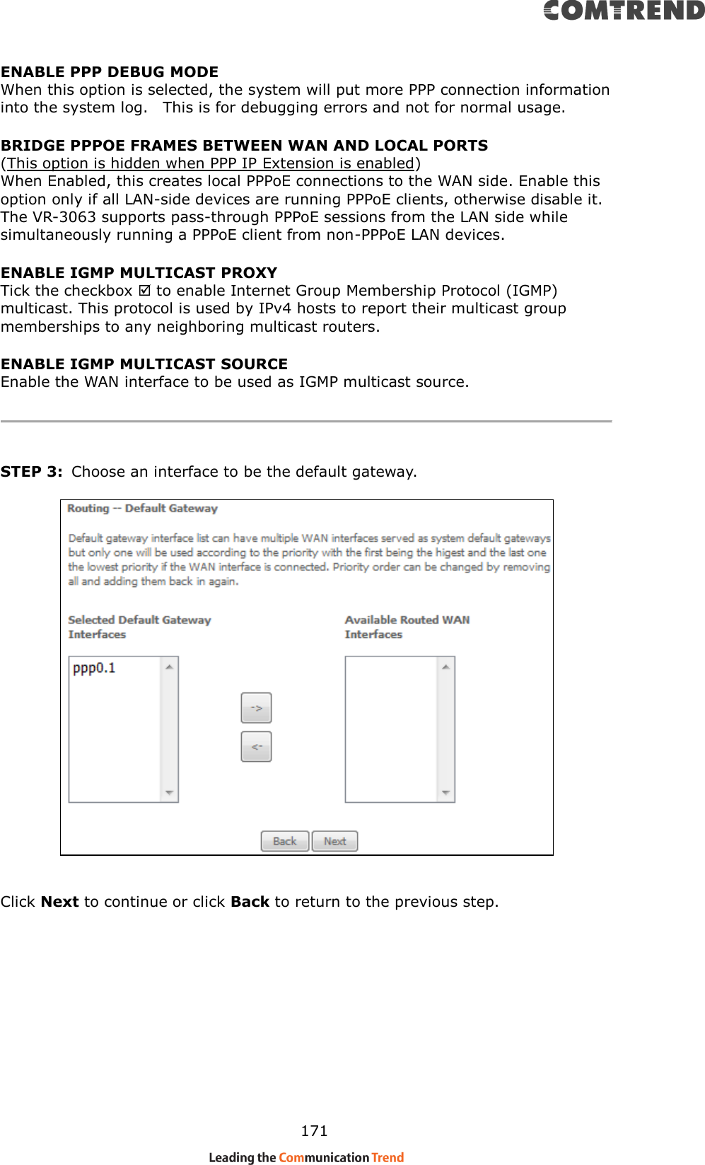
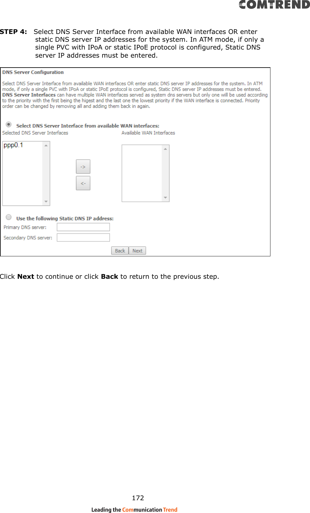
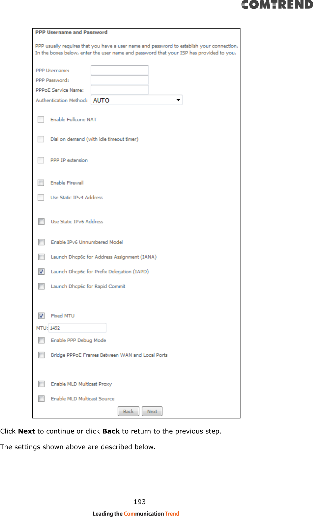
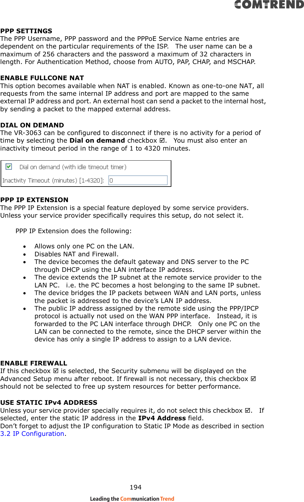
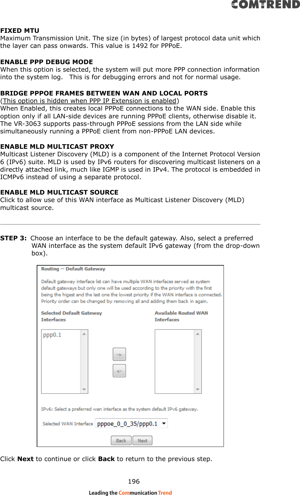
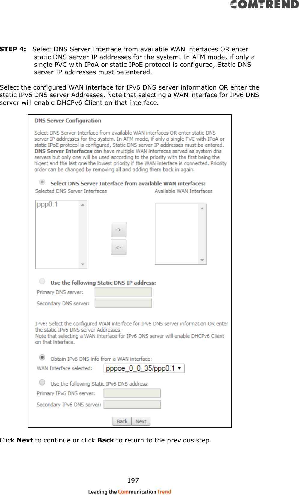
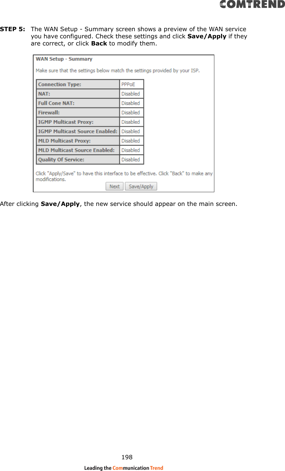
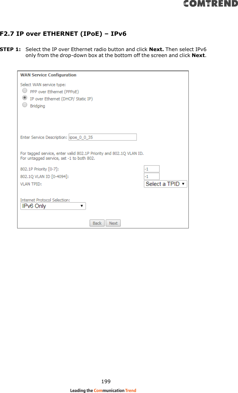
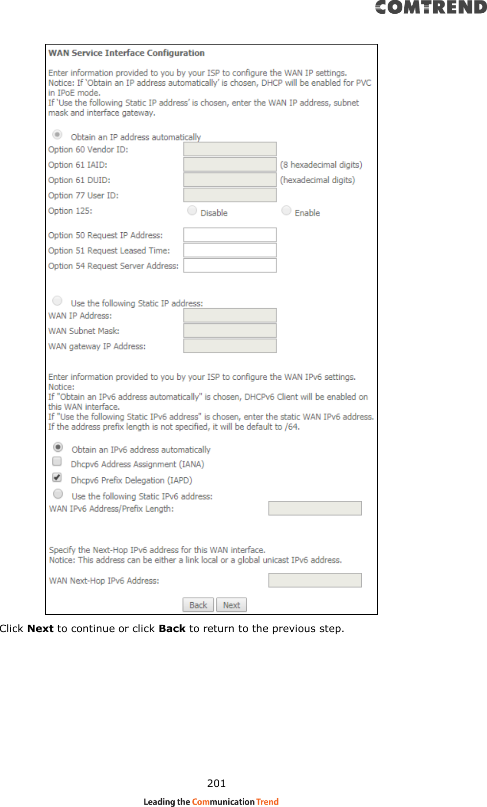
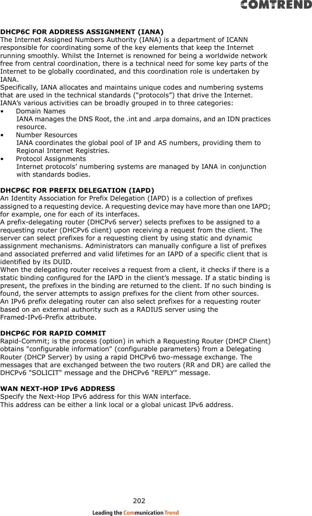
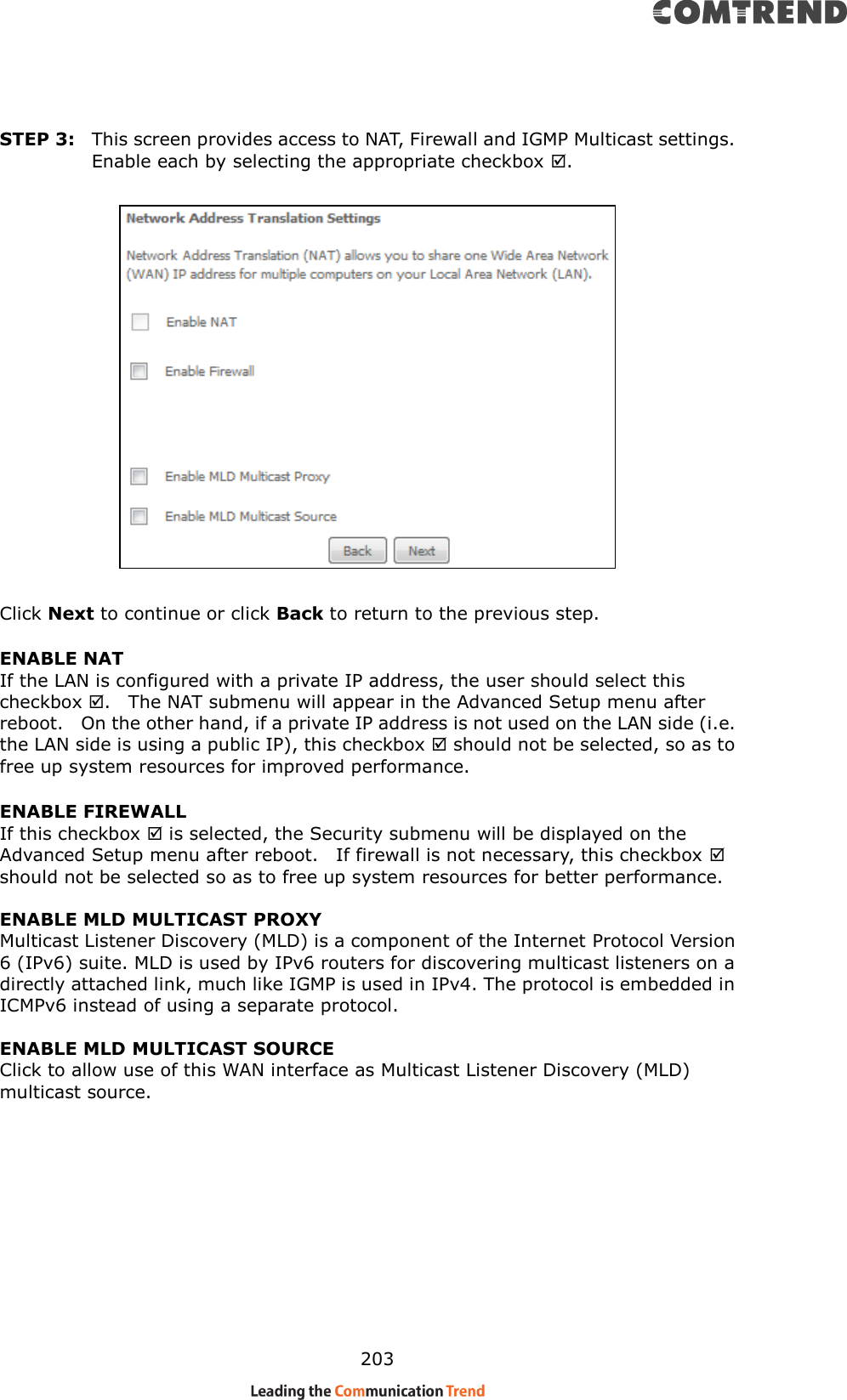
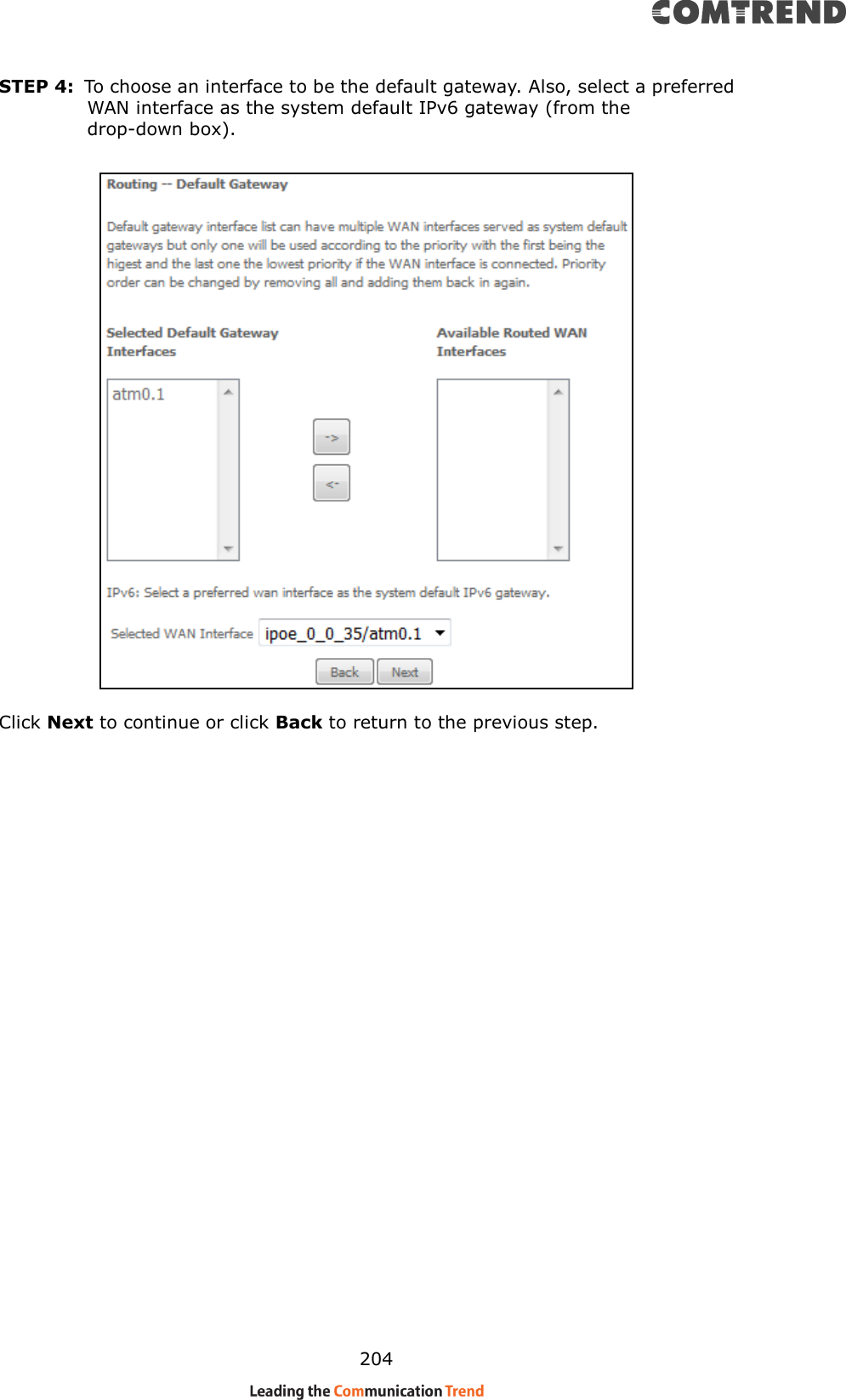
User Manual III
User Manual III
Navigation menu
Upload a User Manual
Namespaces
Wiki Guide
HTML
PDF
Info
Views
User Manual
Discussion / Help
Navigation