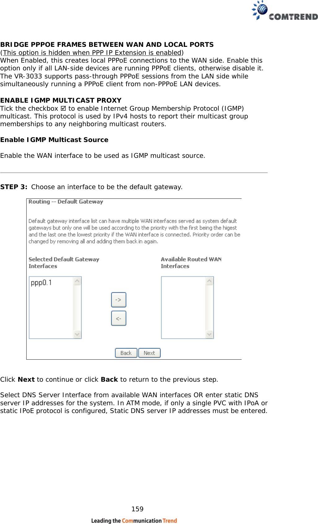
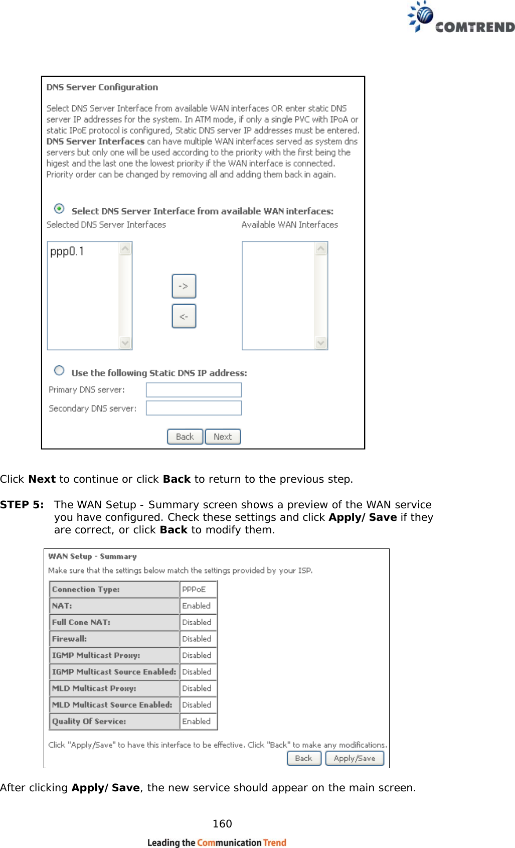
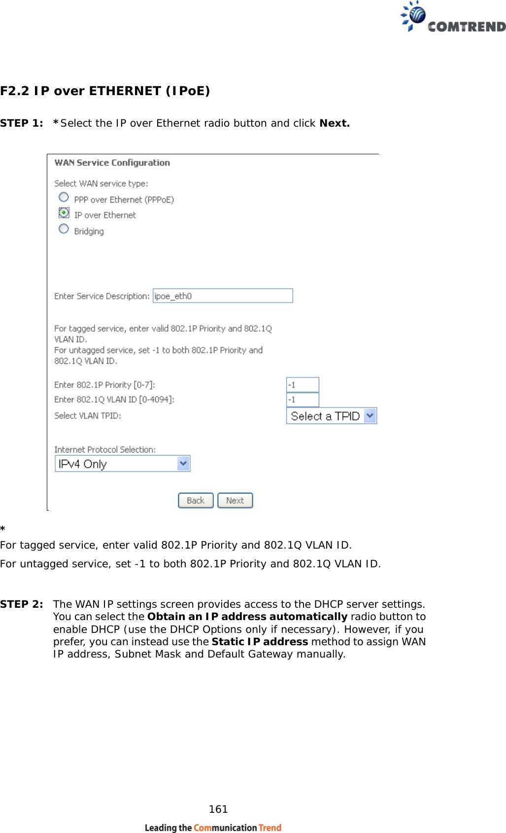
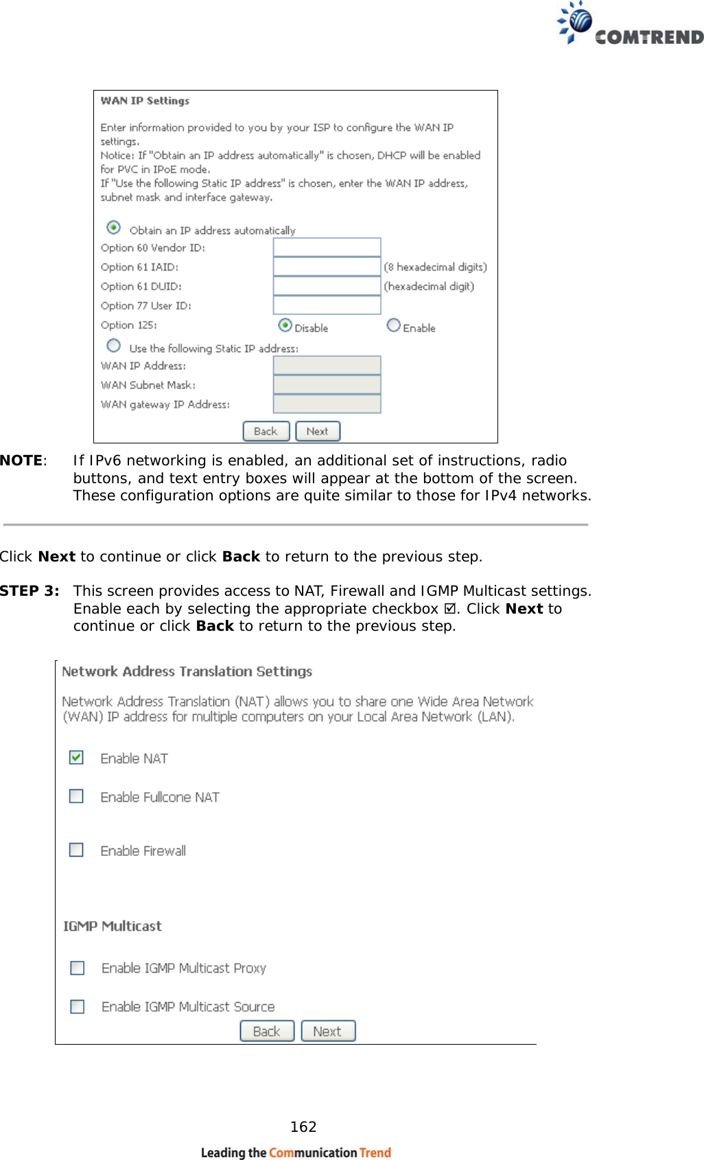
Comtrend VR-3033U Multi-DSL Wireless Router User Manual UM VR3033 A1 1 02

Comtrend Corporation Multi-DSL Wireless Router UM VR3033 A1 1 02

Contents

User manual 2

   110 Chapter 7 Diagnostics You can reach this page by clicking on the following icon located at the top of the screen.  7.1 Diagnostics – Individual Tests The first Diagnostics screen is a dashboard that shows overall connection status.     Click the Diagnostics Menu item on the left side of the screen to display the individual connections.
   111 7.2 Ethernet OAM  The Ethernet OAM page provides settings to enable/disable 802.3ah, 802.1ag/Y1.731 OAM protocols.    To enable Ethernet Link OAM (802.3 ah), click Enabled to display the full configuration list.  At least one option must be enabled for 802.1ah.     WAN Interface Select layer 2 WAN interface for outgoing OAM packetsOAM IDOAM Identification number Auto EventSupports OAM auto eventVariable Retrieval Supports OAM variable retrievalLink EventsSupports OAM link eventsRemote Loopback Supports OAM remove loopbackActive modeSupports OAM active mode
   112 To enable Ethernet Service OAM (802.1ag/Y1731), click Enabled to display the full configuration list.       WAN Interface Select from the list of WAN Interfaces to send OAM packets MD Level Maintenance Domain Level MD Name Maintenance Domain name  MA ID Maintenance Association Identifier Local MEP ID Local Maintenance association End Point Identifier Local MEP VLAN ID VLAN IP used for Local Maintenance End point  Click CCM Transmission to enable CPE sending Continuity Check Message (CCM) continuously.  Remote MEP ID Maintenance association End Point Identifier for the remote receiver  To perform Loopback/Linktrace OAM test, enter the Target MAC of the destination and click “Send Loopback” or “Send Linktrace” button.  Target MAC MAC Address of the destination to send OAM loopback/linktrace packet Linktrace TTL Time to Live value for the loopback/linktrace packet
   113 7.3 Uptime Status This page shows System, DSL, ETH and Layer 3 uptime. If the DSL line, ETH or Layer 3 connection is down, the uptime will stop incrementing. If the service is restored, the counter will reset and start from 0. A Bridge interface will follow the DSL or ETH timer.   The "ClearAll" button will restart the counters from 0 or show "Not Connected" if the interface is down.
   114 7.4 Ping  Input the IP address/hostname and click the Ping button to execute ping diagnostic test to send the ICMP request to the specified host.
   115 7.5 Trace Route Input the IP address/hostname and click the TraceRoute button to execute the trace route diagnostic test to send the ICMP packets to the specified host.
   116 Chapter 8 Management You can reach this page by clicking on the following icon located at the top of the screen.    The Management menu has the following maintenance functions and processes:   8.1 Settings This includes Backup Settings, Update Settings, and Restore Default screens.   8.1.1 Backup Settings  To save the current configuration to a file on your PC, click Backup Settings.  You will be prompted for backup file location. This file can later be used to recover settings on the Update Settings screen, as described below.
   117 8.1.2 Update Settings This option recovers configuration files previously saved using Backup Settings.  Enter the file name (including folder path) in the Settings File Name box, or press Browse… to search for the file, then click Update Settings to recover settings.   8.1.3 Restore Default Click Restore Default Settings to restore factory default settings.   After Restore Default Settings is clicked, the following screen appears.    Close the browser and wait for 2 minutes before reopening it. It may also be necessary, to reconfigure your PC IP configuration to match any new settings.
   118 NOTE:   This entry has the same effect as the Reset button. The VR-3033 board hardware and the boot loader support the reset to default. If the Reset button is continuously pressed for more than 10 seconds, the boot loader will erase the configuration data saved in flash memory.
   119 8.2 System Log This function allows a system log to be kept and viewed upon request.    Follow the steps below to configure, enable, and view the system log.  STEP 1:  Click Configure System Log, as shown below (circled in Red).    STEP 2:  Select desired options and click Apply/Save.    Consult the table below for detailed descriptions of each system log option.  Option  Description Log   Indicates whether the system is currently recording events.  The user can enable or disable event logging.  By default, it is disabled.  To enable it, select the Enable radio button and then click Apply/Save.
   120 Option  Description Log Level  Allows you to configure the event level and filter out unwanted events below this level.  The events ranging from the highest critical level “Emergency” down to this configured level will be recorded to the log buffer on the VR-3033 SDRAM.  When the log buffer is full, the newer event will wrap up to the top of the log buffer and overwrite the old event. By default, the log level is “Debugging”, which is the lowest critical level.   The log levels are defined as follows:  •  Emergency = system is unusable •  Alert = action must be taken immediately •  Critical = critical conditions •  Error = Error conditions •  Warning = normal but significant condition •  Notice= normal but insignificant condition •  Informational= provides information for reference •  Debugging = debug-level messages  Emergency is the most serious event level, whereas Debugging is the least important.   For instance, if the log level is set to Debugging, all the events from the lowest Debugging level to the most critical level Emergency level will be recorded.  If the log level is set to Error, only Error and the level above will be logged. Display Level  Allows the user to select the logged events and displays on the View System Log window for events of this level and above to the highest Emergency level. Mode  Allows you to specify whether events should be stored in the local memory, or be sent to a remote system log server, or both simultaneously.  If remote mode is selected, view system log will not be able to display events saved in the remote system log server.   When either Remote mode or Both mode is configured, the WEB UI will prompt the user to enter the Server IP address and Server UDP port.  STEP 3:  Click View System Log.  The results are displayed as follows.
   121 8.3 SNMP Agent Simple Network Management Protocol (SNMP) allows a management application to retrieve statistics and status from the SNMP agent in this device.  Select the Enable radio button, configure options, and click Save/Apply to activate SNMP.
   122 8.4 TR-069 Client WAN Management Protocol (TR-069) allows an Auto-Configuration Server (ACS) to perform auto-configuration, provision, collection, and diagnostics to this device.  Select desired values and click Apply/Save to configure TR-069 client options.    The table below is provided for ease of reference.   Option  Description Enable TR-069  Tick the checkbox  to enable. OUI-serial  The serial number used to identify the CPE when making a connection to the ACS using the CPE WAN Management Protocol.  Select MAC to use the router’s MAC address as serial number to authenticate with ACS or select serial number to use router’s serial number. Inform  Disable/Enable TR-069 client on the CPE. Inform Interval  The duration in seconds of the interval for which the CPE MUST attempt to connect with the ACS and call the Inform method. ACS URL  URL for the CPE to connect to the ACS using the CPE WAN Management Protocol. This parameter MUST be in the form of a valid HTTP or HTTPS URL. An HTTPS URL indicates that the ACS supports SSL. The “host” portion of this URL is used by the CPE for validating the certificate from the ACS when using certificate-based authentication.
   123 Option  Description ACS User Name  Username used to authenticate the CPE when making a connection to the ACS using the CPE WAN Management Protocol. This username is used only for HTTP-based authentication of the CPE. ACS Password  Password used to authenticate the CPE when making a connection to the ACS using the CPE WAN Management Protocol. This password is used only for HTTP-based authentication of the CPE. WAN Interface used by TR-069 client  Choose Any_WAN, LAN, Loopback or a configured connection. Connection Request Authentication   Tick the checkbox  to enable. User Name  Username used to authenticate an ACS making a Connection Request to the CPE. Password  Password used to authenticate an ACS making a Connection Request to the CPE. URL  IP address and port the ACS uses to connect to router.  The Send Inform button forces the CPE to establish an immediate connection to the ACS.
   124 8.5 Internet Time This option automatically synchronizes the router time with Internet timeservers.  To enable time synchronization, tick the corresponding checkbox , choose your preferred time server(s), select the correct time zone offset, and click Save/Apply.     NOTE:  Internet Time must be activated to use 5.5 Parental Control.  In addition, this menu item is not displayed when in Bridge mode since the router would not be able to connect to the NTP timeserver.
   125 8.6 Access Control 8.6.1 Passwords This screen is used to configure the user account access passwords for the device.  Access to the VR-3033 is controlled through the following user accounts:  • The root account has unrestricted access to view and change the configuration of your Broadband router.  • The support account is typically utilized by Carrier/ISP technicians for maintenance and diagnostics.  • The user account is typically utilized by End-Users to view configuration settings and statistics, with limited ability to configure certain settings.  • The apuser account is typically utilized by End-Users to view configuration settings and statistics, with limited ability to configure wireless settings.   Use the fields to update passwords for the accounts, add/remove accounts (max of 5 accounts) as well as adjust their specific privileges.
   126   Note: Passwords may be as long as 16 characters but must not contain a space.   Click Save/Apply to continue.
   127 8.6.2  Services The Services option limits or opens the access services over the LAN or WAN.  These access services available are: FTP, HTTP, ICMP, SNMP, TELNET and TFTP.  Enable a service by selecting its dropdown listbox.  Click Apply/Save to activate.
   128  8.6.3  IP Address The IP Address Access Control mode, if enabled, permits access to local management services from IP addresses contained in the Access Control List. If the Access Control mode is disabled, the system will not validate IP addresses for incoming packets. The services are the system applications listed in the Service Control List beside ICMP.     Click the Add button to display the following.    Configure the address and subnet of the management station permitted to access the local management services, and click Save/Apply.  IP Address – IP address of the management station.  Subnet Mask – Subnet address for the management station.  Interface – Access permission for the specified address, allowing the address to access the local management service from none/lan/wan/lan&wan interfaces.
   129 8.7 Wake-on-LAN  This tool allows you to wake up (power on) computers connected to the Broadband Router LAN interface by sending special "magic packets". The network interface card in the computer or device that is going to be woken up must support Wake-on-LAN.     LAN Interface – Select the LAN interface to send the Wake-on-LAN packet.  MAC Address – Specify the MAC address of the device that is going to be woken up.  Click the Wake Up! button to send the magic packet out to the LAN interface.
   130 8.8 Update Software This option allows for firmware upgrades from a locally stored file.    STEP 1:  Obtain an updated software image file from your ISP. STEP 2:  Select the configuration from the drop-down menu.  Configuration options:   No change – upgrade software directly.  Erase current config – If the router has save_default configuration, this option will erase the current configuration and restore to save_default configuration after software upgrade.  Erase All – Router will be restored to factory default configuration after software upgrade.  STEP 3:  Enter the path and filename of the firmware image file in the Software File Name field or click the Browse button to locate the image file. STEP 4:  Click the Update Software button once to upload and install the file.  NOTE:   The update process will take about 2 minutes to complete.  The device will reboot and the browser window will refresh to the default screen upon successful installation. It is recommended that you compare the Software Version on the Device Information screen with the firmware version installed, to confirm the installation was successful.
   131 8.9 Reboot To save the current configuration and reboot the router, click Save/Reboot.     NOTE:  You may need to close the browser window and wait for 2 minutes before reopening it. It may also be necessary, to reset your PC IP configuration.
   132 Chapter 9 Logout To log out from the device simply click the following icon located at the top of your screen.    When the following window pops up, click the OK button to exit the router.    Upon successful exit, the following message will be displayed.
   133 Appendix A - Firewall STATEFUL PACKET INSPECTION Refers to an architecture, where the firewall keeps track of packets on each connection traversing all its interfaces and makes sure they are valid. This is in contrast to static packet filtering which only examines a packet based on the information in the packet header. DENIAL OF SERVICE ATTACK Is an incident in which a user or organization is deprived of the services of a resource they would normally expect to have. Various DoS attacks the device can withstand are ARP Attack, Ping Attack, Ping of Death, Land, SYN Attack, Smurf Attack, and Tear Drop. TCP/IP/PORT/INTERFACE FILTER These rules help in the filtering of traffic at the Network layer (i.e. Layer 3). When a Routing interface is created, Enable Firewall must be checked. Navigate to Advanced Setup  Security  IP Filtering. OUTGOING IP FILTER Helps in setting rules to DROP packets from the LAN interface. By default, if the Firewall is Enabled, all IP traffic from the LAN is allowed. By setting up one or more filters, specific packet types coming from the LAN can be dropped.     Example 1:  Filter Name      : Out_Filter1 Protocol    : TCP Source IP address    : 192.168.1.45 Source Subnet Mask  : 255.255.255.0 Source Port      : 80 Dest. IP Address    : NA Dest. Subnet Mask   : NA Dest. Port      : NA   This filter will Drop all TCP packets coming from the LAN with IP Address/Subnet Mask of 192.168.1.45/24 having a source port of 80 irrespective of the destination. All other packets will be Accepted.  Example 2:  Filter Name      : Out_Filter2 Protocol    : UDP Source IP Address   : 192.168.1.45 Source Subnet Mask  : 255.255.255.0 Source Port      : 5060:6060 Dest. IP Address    : 172.16.13.4 Dest. Subnet Mask   : 255.255.255.0 Dest. Port      : 6060:7070  This filter will drop all UDP packets coming from the LAN with IP Address / Subnet Mask of 192.168.1.45/24 and a source port range of 5060 to 6060, destined to 172.16.13.4/24 and a destination port range of 6060 to 7070. INCOMING IP FILTER Helps in setting rules to Allow or Deny packets from the WAN interface. By default, all incoming IP traffic from the WAN is Blocked, if the Firewall is Enabled. By setting up one or more filters, specific packet types coming from the WAN can be Accepted.
   134  Example 1:  Filter Name      : In_Filter1 Protocol    : TCP Policy    : Allow Source IP Address   : 210.168.219.45 Source Subnet Mask  : 255.255.0.0 Source Port      : 80 Dest. IP Address    : NA Dest. Subnet Mask   : NA Dest. Port      : NA Selected WAN interface : br0  This filter will ACCEPT all TCP packets coming from WAN interface “br0” with IP Address/Subnet Mask 210.168.219.45/16 with a source port of 80, irrespective of the destination. All other incoming packets on this interface are DROPPED.  Example 2:  Filter Name      : In_Filter2 Protocol    : UDP Policy    : Allow Source IP Address   : 210.168.219.45 Source Subnet Mask  : 255.255.0.0 Source Port      : 5060:6060 Dest. IP Address    : 192.168.1.45 Dest. Sub. Mask    : 255.255.255.0 Dest. Port      : 6060:7070 Selected WAN interface : br0   This rule will ACCEPT all UDP packets coming from WAN interface “br0” with IP Address/Subnet Mask 210.168.219.45/16 and a source port in the range of 5060 to 6060, destined to 192.168.1.45/24 and a destination port in the range of 6060 to 7070. All other incoming packets on this interface are DROPPED.  MAC LAYER FILTER These rules help in the filtering of Layer 2 traffic. MAC Filtering is only effective in Bridge mode. After a Bridge mode connection is created, navigate to Advanced Setup  Security  MAC Filtering in the WUI.  Example 1:  Global Policy      : Forwarded Protocol Type      : PPPoE Dest. MAC Address   : 00:12:34:56:78:90 Source MAC Address  : NA Src. Interface     : eth1 Dest. Interface    : eth2  Addition of this rule drops all PPPoE frames going from eth1 to eth2 with a Destination MAC Address of 00:12:34:56:78:90 irrespective of its Source MAC Address. All other frames on this interface are forwarded.  Example 2:  Global Policy      : Blocked Protocol Type      : PPPoE Dest. MAC Address   : 00:12:34:56:78:90 Source MAC Address  : 00:34:12:78:90:56 Src. Interface     : eth1 Dest. Interface    : eth2  Addition of this rule forwards all PPPoE frames going from eth1 to eth2 with a Destination MAC Address of 00:12:34:56:78 and Source MAC Address of 00:34:12:78:90:56. All other frames on this interface are dropped.
   135 DAYTIME PARENTAL CONTROL This feature restricts access of a selected LAN device to an outside Network through the VR-3033, as per chosen days of the week and the chosen times.  Example:  User Name      : FilterJohn Browser's MAC Address : 00:25:46:78:63:21 Days of the Week    : Mon, Wed, Fri Start Blocking Time  : 14:00 End Blocking Time   : 18:00  With this rule, a LAN device with MAC Address of 00:25:46:78:63:21 will have no access to the WAN on Mondays, Wednesdays, and Fridays, from 2pm to 6pm. On all other days and times, this device will have access to the outside Network.
   136 Appendix B - Pin Assignments   ETHERNET Ports (RJ45)  Pin  Definition  Pin  Definition 1  Transmit data+ 5  NC 2  Transmit data- 6  Receive data- 3  Receive data+  7  NC 4  NC  8  NC
   137 Appendix C - Specifications Hardware Interface RJ-11 X 1 for ADSL2+/VDSL2, RJ-45 X 4 for LAN (10/100 Base-T), Reset Button X 1, WPS/WiFi on/off button x1, Wi-Fi Antennas X 2, Power Switch X 1, USB Host  WAN Interface        ADSL2+  ....... Downstream : 24 Mbps   Upstream : 1.3 Mbps        ITU-T G.992.5, ITU-T G.992.3, ITU-T G.992.1, ANSI T1.413 Issue 2, AnnexM         VDSL2  ......... Downstream : 100 Mbps   Upstream : 60 Mbps        ITU-T G.993.2 (supporting profile 8a, 8b, 8c, 8d, 12a, 12b, 17a) LAN Interface  Standard ..................... IEEE 802.3, IEEE 802.3u  10/100 BaseT .............. Auto-sense  MDI/MDX support ......... Yes WLAN Interface Standard  ................... IEEE802.11b/g/n  Encryption................... 64/128-bit Wired Equivalent Privacy (WEP) Channels ..................... 11 (US, Canada)/ 13 (Europe)/ 14 (Japan) Data Rate ................... Up to 300Mbps WEP ........................... Yes WPA ...........................  Yes IEEE 802.1x ................ Yes MAC Filtering ............... Yes ATM Attributes  RFC 2684 (RFC 1483) Bridge/Route; RFC 2516 (PPPoE);  RFC 2364 (PPPoA); RFC 1577 (IPoA)                                             PVCs  ......................... 16  AAL type ..................... AAL5    ATM service class ......... UBR/CBR/VBR    ATM UNI support .......... UNI 3.1/4.0  OAM F4/F5 .................. Yes   PTM Attributes  ATM Adaptation Layer: Ethernet packet format,   Support 8 flows,  Support preemption and dual latency,        Support PTM shaping Management Compliant with TR-069/TR-098/TR-104/TR-111 remote management protocols, Telnet, Web-based management, Configuration backup and restoration, Software upgrade via HTTP / TFTP / FTP server
   138 Bridge Functions   Transparent bridging and learning ............ IEEE 802.1d  VLAN support ....................................... Yes   Spanning Tree Algorithm ........................ Yes  IGMP Proxy .......................................... Yes Routing Functions Static route, RIP v1/v2, NAT/PAT, DHCP Server/Client/Relay, DNS Proxy, ARP,  Security Functions Authentication protocols : PAP, CHAP TCP/IP/Port filtering rules, Packet and MAC address filtering, Access Control, SSH QoS ................................................. L3  policy-based  QoS, IP QoS, ToS Application Passthrough PPTP, L2TP, IPSec, VoIP, Yahoo messenger, ICQ, RealPlayer, NetMeeting, MSN, X-box   Power Supply ............................................... Input:  100 - 240 Vac    Output:  12 Vdc / 1.0 A Environment Condition  Operating temperature ........................... 0 ~ 40 degrees Celsius           Relative humidity .................................. 5 ~ 95% (non-condensing)                        Dimensions .................................. 173 mm (W) x 39 mm (H) x 127.2 mm (D) Kit Weight (1*VR-3033, 1*RJ11 cable, 1*RJ45 cable, 1*power adapter) = 0.6 kg                            NOTE:   Specifications are subject to change without notice
   139 Appendix D - SSH Client Unlike Microsoft Windows, Linux OS has a ssh client included.   For Windows users, there is a public domain one called “putty” that can be downloaded from here:  http://www.chiark.greenend.org.uk/~sgtatham/putty/download.html  To access the ssh client you must first enable SSH access for the LAN or WAN from the Management  Access Control  Services menu in the web user interface.    To access the router using the Linux ssh client   For LAN access, type: ssh -l admin 192.168.1.1  For WAN access, type: ssh -l support WAN IP address  To access the router using the Windows “putty” ssh client  For LAN access, type: putty -ssh -l admin 192.168.1.1  For WAN access, type: putty -ssh -l support WAN IP address  NOTE:  The WAN IP address can be found on the Device Info  WAN screen
   140 Appendix E - Printer Server These steps explain the procedure for enabling the Printer Server.   NOTE:  This function only applies to models with a USB host port.     STEP 1:  Enable Print Server from Web User Interface. Select Enable on-board print server checkbox  and enter Printer name and Make and model  NOTE: The Printer name can be any text string up to 40 characters.    The Make and model can be any text string up to 128 characters.     STEP 2:  Go to the Printers and Faxes application in the Control Panel and select the Add a printer function (as located on the side menu below).
   141   STEP 3: Click Next to continue when you see the dialog box below.    STEP 4: Select Network Printer and click Next.
   142   STEP 5:  Select Connect to a printer on the Internet and enter your printer link.   (e.g. http://192.168.1.1:631/printers/hp3845) and click Next.    NOTE:   The printer name must be the same name entered in the ADSL modem WEB UI “printer server setting” as in step 1.   STEP 6:  Click Have Disk and insert the printer driver CD.
   143   STEP 7:  Select driver file directory on CD-ROM and click OK.    STEP 8:  Once the printer name appears, click OK.
   144   STEP 9:  Choose Yes or No for default printer setting and click Next.    STEP 10: Click Finish.
   145
   146 STEP 11: Check the status of printer from Windows Control Panel, printer window.   Status should show as Ready.
   147 Appendix F - Connection Setup Creating a WAN connection is a two-stage process.   1 - Setup a Layer 2 Interface (ATM, PTM or Ethernet).  2 - Add a WAN connection to the Layer 2 Interface.  The following sections describe each stage in turn. F1 ~ Layer 2 Interfaces        Every layer2 interface operates in Multi-Service Connection (VLAN MUX) mode, which supports multiple connections over a single interface. Note that PPPoA and IPoA connection types are not supported for Ethernet WAN interfaces. After adding WAN connections to an interface, you must also create an Interface Group to connect LAN/WAN interfaces.  F1.1 ATM Interfaces Follow these procedures to configure an ATM interface.  NOTE:  The VR-3033 supports up to 16 ATM interfaces.   STEP 1:  Go to Basic Setup    WAN Setup  Select ATM Interface from the drop-down menu.       This table is provided here for ease of reference.
   148 Heading  Description Interface  WAN interface name. VPI  ATM VPI (0-255)  VCI  ATM VCI (32-65535) DSL Latency  {Path0}  portID = 0  {Path1}  port ID = 1 {Path0&1}  port ID = 4  Category  ATM service category Peak Cell Rate  Maximum allowed traffic rate for the ATM PCR service connection Sustainable Cell Rate  The average allowable, long-term cell transfer rate on the VBR service connection Max Burst Size  The maximum allowable burst size of cells that can be transmitted contiguously on the VBR service connection Link Type  Choose EoA (for PPPoE, IPoE, and Bridge), PPPoA, or IPoA. Connection Mode  Default Mode – Single service over one connection Vlan Mux Mode – Multiple Vlan service over one connection IP QoS  Quality of Service (QoS) status Remove  Select items for removal   STEP 2:  Click Add to proceed to the next screen.   NOTE:  To add WAN connections to one interface type, you must delete existing connections from the other interface type using the remove button.
   149   There are many settings here including: VPI/VCI, DSL Latency, DSL Link Type, Encapsulation Mode, Service Category, Connection Mode and Quality of Service.     Here are the available encapsulations for each xDSL Link Type:    EoA- LLC/SNAP-BRIDGING, VC/MUX   PPPoA- VC/MUX, LLC/ENCAPSULATION   IPoA- LLC/SNAP-ROUTING, VC MUX   STEP 3:  Click Apply/Save to confirm your choices.   On the next screen, check that the ATM interface is added to the list. For example, an ATM interface on PVC 0/35 in Default Mode with an EoA Link type is shown below.
   150   To add a WAN connection go to Section F2 ~ WAN Connections.  F1.2 PTM Interfaces Follow these procedures to configure a PTM interface.    NOTE:  The VR-3033 supports up to four PTM interfaces.   STEP 1:  Go to Basic Setup    WAN Setup  Select PTM Interface from the drop-down menu.     This table is provided here for ease of reference.  Heading  Description Interface  WAN interface name. DSL Latency  {Path0}  portID = 0  {Path1}  port ID = 1 {Path0&1}  port ID = 4  PTM Priority  Normal or High Priority (Preemption).
   151 Heading  Description Connection Mode  Default Mode – Single service over one interface. Vlan Mux Mode – Multiple Vlan services over one interface. IP QoS  Quality of Service (QoS) status. Remove  Select interfaces to remove.  STEP 2:  Click Add to proceed to the next screen.    NOTE:  To add WAN connections to one interface type, you must delete existing connections from the other interface type using the remove button.       Default PTM interface Quality of Service can be configured here, including Scheduler, Queue Weight and Rate Limit.  STEP 3:  Click Apply/Save to confirm your choices.   On the next screen, check that the PTM interface is added to the list.   For example, an PTM interface in Default Mode is shown below.      To add a WAN connection go to Section F2 ~ WAN Connections.
   152 F1.3 Ethernet WAN Interface The VR-3033 supports a single Ethernet WAN interface over the ETH WAN port. Follow these procedures to configure an Ethernet interface.     STEP 1:  Go to Basic Setup    WAN Setup  Select ETHERNET Interface from the drop-down menu.       This table is provided here for ease of reference.   Heading  Description Interface/ (Name)  WAN interface name. Connection Mode  Default Mode – Single service over one interface. Vlan Mux Mode – Multiple Vlan services over one interface. Remove  Select interfaces to remove.  STEP 2:  Click Add to proceed to the next screen.
   153    STEP 3:  Select an Ethernet port and Click Apply/Save to confirm your choices.    On the next screen, check that the ETHERNET interface is added to the list.         To add a WAN connection go to Section F2 ~ WAN Connections.
   154 F2 ~ WAN Connections The VR-3033 supports one WAN connection for each interface, up to a maximum of 16 connections.  To setup a WAN connection follow these instructions.  STEP 1:  Go to Basic Setup    WAN Setup.     STEP 2:  Click Add to create a WAN connection. The following screen will display.    STEP 3:  Choose a layer 2 interface from the drop-down box and click Next.  The WAN Service Configuration screen will display as shown below.
   155   NOTE:  The WAN services shown here are those supported by the layer 2 interface you selected in the previous step. If you wish to change your selection click the Back button and select a different layer 2 interface.  STEP 4:  For VLAN Mux Connections only, you must enter Priority & VLAN ID tags.    Select a TPID if VLAN tag Q-in-Q is used.  STEP 5:  You will now follow the instructions specific to the WAN service type you wish to establish. This list should help you locate the correct procedure: (1) For F2.1 PPP over ETHERNET (PPPoE), go to page 154. (2) For F2.2 IP over ETHERNET (IPoE), go to page 159. (3) For F2.3 Bridging, go to page 164. (4) For F2.4 PPP over ATM (PPPoA), go to page 166. (5) For F2.5 IP over ATM (IPoA), go to page 170.     The subsections that follow continue the WAN service setup procedure.
   156 F2.1 PPP over ETHERNET (PPPoE) STEP 1:  Select the PPP over Ethernet radio button and click Next. You can also enable IPv6 by ticking the checkbox  at the bottom of this screen.     STEP 2:  On the next screen, enter the PPP settings as provided by your ISP.  Click Next to continue or click Back to return to the previous step.
   157   The settings shown above are described below. PPP SETTINGS The PPP Username, PPP password and the PPPoE Service Name entries are dependent on the particular requirements of the ISP.  The user name can be a maximum of 256 characters and the password a maximum of 32 characters in length. For Authentication Method, choose from AUTO, PAP, CHAP, and MSCHAP. ENABLE FULLCONE NAT This option becomes available when NAT is enabled. Known as one-to-one NAT, all requests from the same internal IP address and port are mapped to the same external IP address and port. An external host can send a packet to the internal host, by sending a packet to the mapped external address.
   158 DIAL ON DEMAND The VR-3033 can be configured to disconnect if there is no activity for a period of time by selecting the Dial on demand checkbox .  You must also enter an inactivity timeout period in the range of 1 to 4320 minutes.     PPP IP EXTENSION The PPP IP Extension is a special feature deployed by some service providers.  Unless your service provider specifically requires this setup, do not select it.    PPP IP Extension does the following:  •  Allows only one PC on the LAN. •  Disables NAT and Firewall. •  The device becomes the default gateway and DNS server to the PC through DHCP using the LAN interface IP address. •  The device extends the IP subnet at the remote service provider to the LAN PC.  i.e. the PC becomes a host belonging to the same IP subnet. •  The device bridges the IP packets between WAN and LAN ports, unless the packet is addressed to the device’s LAN IP address. •  The public IP address assigned by the remote side using the PPP/IPCP protocol is actually not used on the WAN PPP interface.  Instead, it is forwarded to the PC LAN interface through DHCP.  Only one PC on the LAN can be connected to the remote, since the DHCP server within the device has only a single IP address to assign to a LAN device. ENABLE NAT If the LAN is configured with a private IP address, the user should select this checkbox . The NAT submenu will appear in the Advanced Setup menu after reboot.   On the other hand, if a private IP address is not used on the LAN side (i.e. the LAN side is using a public IP), this checkbox  should not be selected to free up system resources for better performance.   ENABLE FIREWALL If this checkbox  is selected, the Security submenu will be displayed on the Advanced Setup menu after reboot. If firewall is not necessary, this checkbox  should not be selected to free up system resources for better performance.   USE STATIC IPv4 ADDRESS Unless your service provider specially requires it, do not select this checkbox .  If selected, enter the static IP address in the IPv4 Address field.  Don’t forget to adjust the IP configuration to Static IP Mode as described in section 3.2 IP Configuration. FIXED MTU Maximum Transmission Unit. The size (in bytes) of largest protocol data unit which the layer can pass onwards. This value is 1500 for PPPoA.  ENABLE PPP DEBUG MODE When this option is selected, the system will put more PPP connection information into the system log.  This is for debugging errors and not for normal usage.
   159 BRIDGE PPPOE FRAMES BETWEEN WAN AND LOCAL PORTS  (This option is hidden when PPP IP Extension is enabled) When Enabled, this creates local PPPoE connections to the WAN side. Enable this option only if all LAN-side devices are running PPPoE clients, otherwise disable it.  The VR-3033 supports pass-through PPPoE sessions from the LAN side while simultaneously running a PPPoE client from non-PPPoE LAN devices.  ENABLE IGMP MULTICAST PROXY Tick the checkbox  to enable Internet Group Membership Protocol (IGMP) multicast. This protocol is used by IPv4 hosts to report their multicast group memberships to any neighboring multicast routers.  Enable IGMP Multicast Source  Enable the WAN interface to be used as IGMP multicast source.     STEP 3:  Choose an interface to be the default gateway.      Click Next to continue or click Back to return to the previous step.  Select DNS Server Interface from available WAN interfaces OR enter static DNS server IP addresses for the system. In ATM mode, if only a single PVC with IPoA or static IPoE protocol is configured, Static DNS server IP addresses must be entered.
   160                                 Click Next to continue or click Back to return to the previous step.  STEP 5:  The WAN Setup - Summary screen shows a preview of the WAN service you have configured. Check these settings and click Apply/Save if they are correct, or click Back to modify them.    After clicking Apply/Save, the new service should appear on the main screen.
   161 F2.2 IP over ETHERNET (IPoE) STEP 1:  *Select the IP over Ethernet radio button and click Next.      * For tagged service, enter valid 802.1P Priority and 802.1Q VLAN ID. For untagged service, set -1 to both 802.1P Priority and 802.1Q VLAN ID.  STEP 2:  The WAN IP settings screen provides access to the DHCP server settings.      You can select the Obtain an IP address automatically radio button to enable DHCP (use the DHCP Options only if necessary). However, if you prefer, you can instead use the Static IP address method to assign WAN IP address, Subnet Mask and Default Gateway manually.
   162  NOTE:  If IPv6 networking is enabled, an additional set of instructions, radio buttons, and text entry boxes will appear at the bottom of the screen.  These configuration options are quite similar to those for IPv4 networks.   Click Next to continue or click Back to return to the previous step.  STEP 3:  This screen provides access to NAT, Firewall and IGMP Multicast settings. Enable each by selecting the appropriate checkbox . Click Next to continue or click Back to return to the previous step.
   163 ENABLE NAT If the LAN is configured with a private IP address, the user should select this checkbox .  The NAT submenu will appear in the Advanced Setup menu after reboot.   On the other hand, if a private IP address is not used on the LAN side (i.e. the LAN side is using a public IP), this checkbox  should not be selected, so as to free up system resources for improved performance. ENABLE FULLCONE NAT   This option becomes available when NAT is enabled. Known as one-to-one NAT, all requests from the same internal IP address and port are mapped to the same external IP address and port. An external host can send a packet to the internal host, by sending a packet to the mapped external address. ENABLE FIREWALL If this checkbox  is selected, the Security submenu will be displayed on the Advanced Setup menu after reboot.  If firewall is not necessary, this checkbox  should not be selected so as to free up system resources for better performance.   ENABLE IGMP MULTICAST PROXY Tick the checkbox  to enable Internet Group Membership Protocol (IGMP) multicast. This protocol is used by IPv4 hosts to report their multicast group memberships to any neighboring multicast routers.  Enable IGMP Multicast Source  Enable the WAN interface to be used as IGMP multicast source.   STEP 4:  To choose an interface to be the default gateway.    Click Next to continue or click Back to return to the previous step.
   164 STEP 5:  Select DNS Server Interface from available WAN interfaces OR enter static DNS server IP addresses for the system. In ATM mode, if only a single PVC with IPoA or static IPoE protocol is configured, Static DNS server IP addresses must be entered.       Click Next to continue or click Back to return to the previous step.   STEP 6:  The WAN Setup - Summary screen shows a preview of the WAN service you have configured. Check these settings and click Apply/Save if they are correct, or click Back to modify them.
   165   After clicking Apply/Save, the new service should appear on the main screen.
   166 F2.3 Bridging  STEP 1:  *Select the Bridging radio button and click Next.        Allow as IGMP Multicast Source  Click to allow use of this bridge WAN interface as IGMP multicast source.   Allow as MLD Multicast Source   Click to allow use of this bridge WAN interface as MLD multicast source.   * For tagged service, enter valid 802.1P Priority and 802.1Q VLAN ID. For untagged service, set -1 to both 802.1P Priority and 802.1Q VLAN ID. For VLAN tag Q-in-Q service, select the TPID from the list.  STEP 2:  The WAN Setup - Summary screen shows a preview of the WAN service you have configured. Check these settings and click Apply/Save if they are correct, or click Back to return to the previous screen.
   167   After clicking Apply/Save, the new service should appear on the main screen.   NOTE:  If this bridge connection is your only WAN service, the VR-3033 will be inaccessible for remote management or technical support from the WAN.
   168 F2.4 PPP over ATM (PPPoA)    STEP 1:  Click Next to continue.   STEP 2:  On the next screen, enter the PPP settings as provided by your ISP.  Click Next to continue or click Back to return to the previous step.
   169 PPP SETTINGS The PPP username and password are dependent on the requirements of the ISP.  The user name can be a maximum of 256 characters and the password a maximum of 32 characters in length. (Authentication Method: AUTO, PAP, CHAP, or MSCHAP.)  KEEP ALIVE INTERVAL  This option configures the interval between each PPP LCP request and the amount of time to wait for the PPP server to reply to the LCP request.   If the time expired on all requests, the current PPP session would be dropped. ENABLE FULLCONE NAT This option becomes available when NAT is enabled. Known as one-to-one NAT, all requests from the same internal IP address and port are mapped to the same external IP address and port. An external host can send a packet to the internal host, by sending a packet to the mapped external address. DIAL ON DEMAND The VR-3033 can be configured to disconnect if there is no activity for a period of time by selecting the Dial on demand checkbox . You must also enter an inactivity timeout period in the range of 1 to 4320 minutes.     PPP IP EXTENSION The PPP IP Extension is a special feature deployed by some service providers.  Unless your service provider specifically requires this setup, do not select it.    PPP IP Extension does the following:  •  Allows only one PC on the LAN. •  Disables NAT and Firewall. •  The device becomes the default gateway and DNS server to the PC through DHCP using the LAN interface IP address. •  The device extends the IP subnet at the remote service provider to the LAN PC.  i.e. the PC becomes a host belonging to the same IP subnet. •  The device bridges the IP packets between WAN and LAN ports, unless the packet is addressed to the device’s LAN IP address. •  The public IP address assigned by the remote side using the PPP/IPCP protocol is actually not used on the WAN PPP interface.  Instead, it is forwarded to the PC LAN interface through DHCP.  Only one PC on the LAN can be connected to the remote, since the DHCP server within the device has only a single IP address to assign to a LAN device. ENABLE NAT If the LAN is configured with a private IP address, the user should select this checkbox . The NAT submenu will appear in the Advanced Setup menu after reboot.   On the other hand, if a private IP address is not used on the LAN side (i.e. the LAN side is using a public IP), this checkbox  should not be selected to free up system resources for better performance.
   170 ENABLE FIREWALL If this checkbox  is selected, the Security submenu will be displayed on the Advanced Setup menu after reboot. If firewall is not necessary, this checkbox  should not be selected to free up system resources for better performance.  USE STATIC IPv4 ADDRESS Unless your service provider specially requires it, do not select this checkbox .  If selected, enter the static IP address in the IP Address field. Also, don’t forget to adjust the IP configuration to Static IP Mode as described in section 3.2.  Fixed MTU Fixed Maximum Transmission Unit. The size (in bytes) of largest protocol data unit which the layer can pass onwards. This value is 1500 for PPPoA.  ENABLE PPP DEBUG MODE When this option is selected, the system will put more PPP connection information into the system log. This is for debugging errors and not for normal usage. ENABLE IGMP MULTICAST PROXY Tick the checkbox  to enable Internet Group Membership Protocol (IGMP) multicast. This protocol is used by IPv4 hosts to report their multicast group memberships to any neighboring multicast routers.  Enable IGMP Multicast Source  Enable the WAN interface to be used as IGMP multicast source.    STEP 3: Choose an interface to be the default gateway.   Click Next to continue or click Back to return to the previous step. STEP 4:  Choose an interface to be the default gateway.
   171  Click Next to continue or click Back to return to the previous step.  STEP 5:  The WAN Setup - Summary screen shows a preview of the WAN service you have configured. Check these settings and click Apply/Save if they are correct, or click Back to modify them.   After clicking Apply/Save, the new service should appear on the main screen.
   172 F2.5 IP over ATM (IPoA)    STEP 1:  Click Next to continue.  STEP 2:  Enter the WAN IP settings provided by your ISP. Click Next to continue.    STEP 3:  This screen provides access to NAT, Firewall and IGMP Multicast settings. Enable each by selecting the appropriate checkbox . Click Next to continue or click Back to return to the previous step.   ENABLE NAT If the LAN is configured with a private IP address, the user should select this checkbox .  The NAT submenu will appear in the Advanced Setup menu after reboot. On the other hand, if a private IP address is not used on the LAN side (i.e. the LAN side is using a public IP), this checkbox  should not be selected, so as to free up system resources for improved performance.
   173  ENABLE FULLCONE NAT This option becomes available when NAT is enabled. Known as one-to-one NAT, all requests from the same internal IP address and port are mapped to the same external IP address and port. An external host can send a packet to the internal host by sending a packet to the mapped external address. ENABLE FIREWALL If this checkbox  is selected, the Security submenu will be displayed on the Advanced Setup menu after reboot.  If firewall is not necessary, this checkbox  should not be selected so as to free up system resources for better performance.   ENABLE IGMP MULTICAST PROXY Tick the checkbox  to enable Internet Group Membership Protocol (IGMP) multicast. This protocol is used by IPv4 hosts to report their multicast group memberships to any neighboring multicast routers.  Enable IGMP Multicast Source  Enable the WAN interface to be used as IGMP multicast source.     STEP 4:  Choose an interface to be the default gateway.       Click Next to continue or click Back to return to the previous step.
   174 NOTE:  If the DHCP server is not enabled on another WAN interface then the following notification will be shown before the next screen.       STEP 5:  Choose an interface to be the default gateway.     Click Next to continue or click Back to return to the previous step.   STEP 6:  The WAN Setup - Summary screen shows a preview of the WAN service you have configured. Check these settings and click Apply/Save if they are correct, or click Back to modify them.
   175   After clicking Apply/Save, the new service should appear on the main screen.

Navigation menu