Comtech EF Data MTSMUV2MT2011 Satellite Modem User Manual MTS User s Manual
Comtech EF Data Satellite Modem MTS User s Manual
UserManual.wiki
>
Comtech EF Data
>
MTSMUV2MT2011 User Manual
>
manual2 2nd half
Contents
1.
manual1 1half
2.
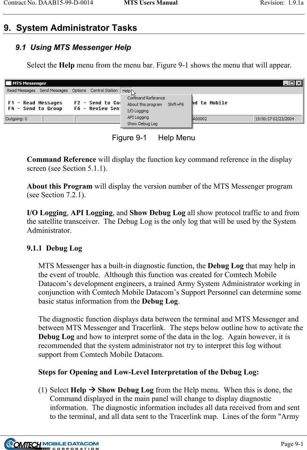
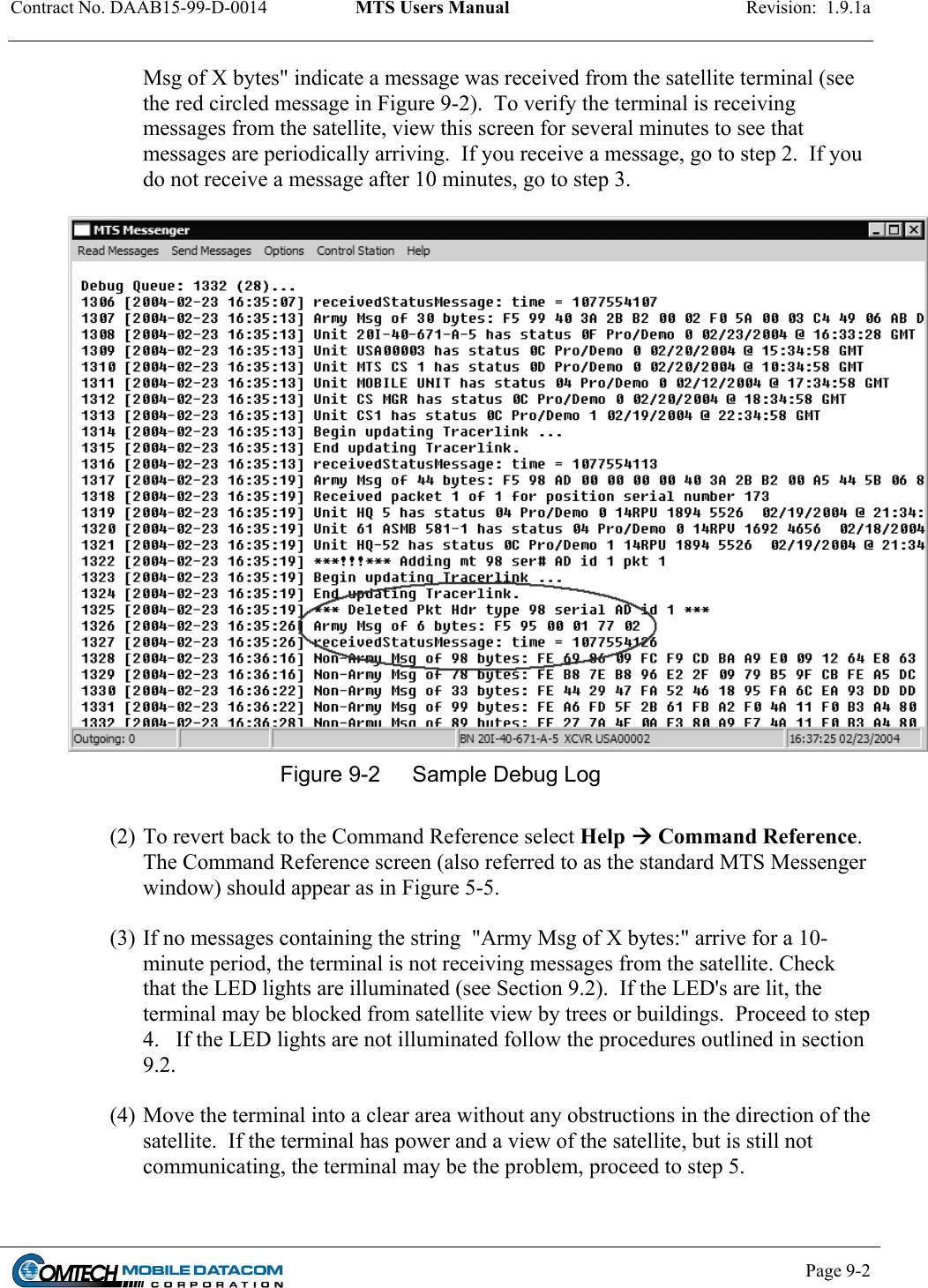
manual2 2nd half
3.
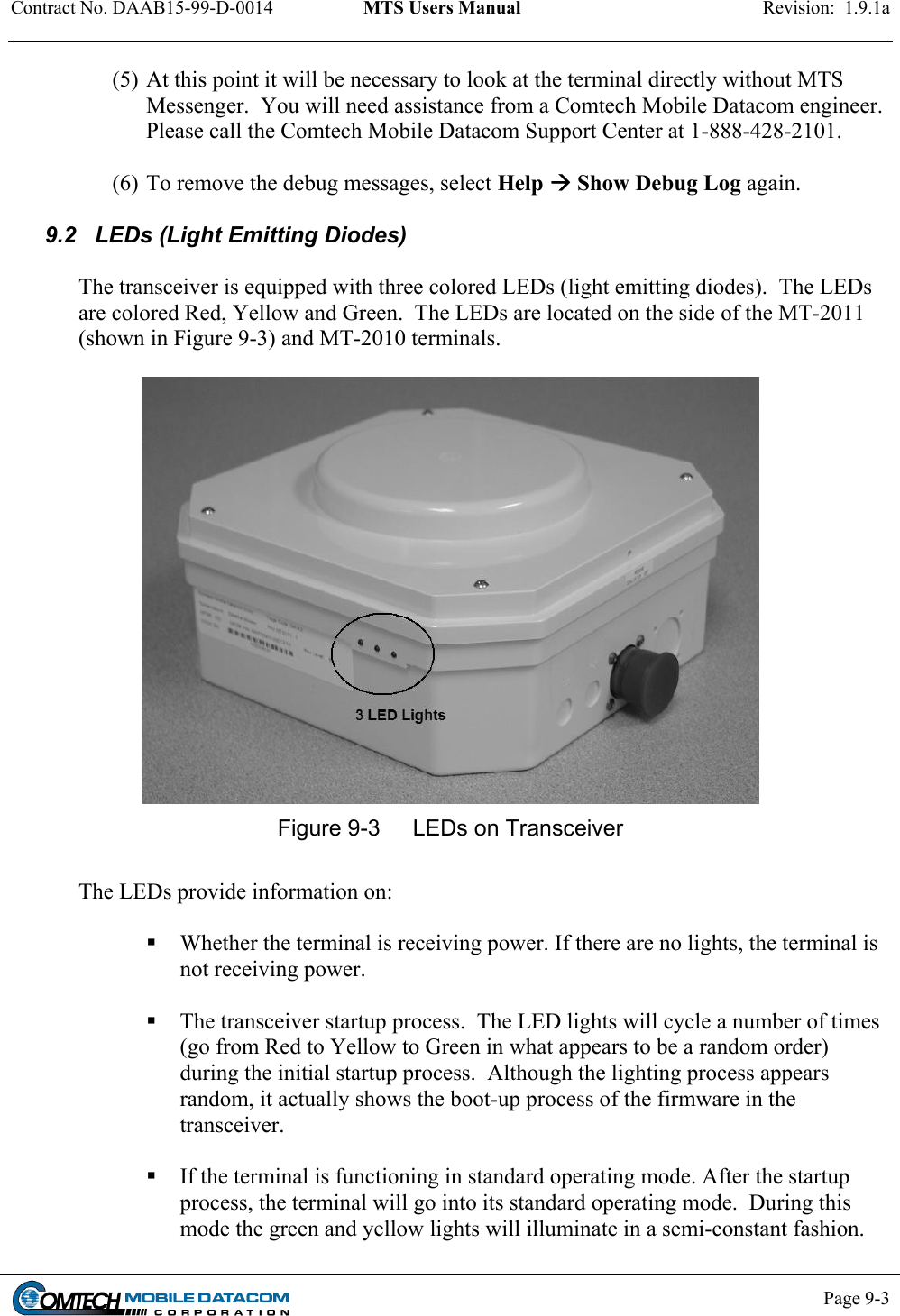
manual3 3rd half
4.
manual4 4th half
5.
manual5 5th half
manual2 2nd half
Navigation menu
Upload a User Manual
Namespaces
Wiki Guide
HTML
PDF
Info
Views
User Manual
Discussion / Help
Navigation