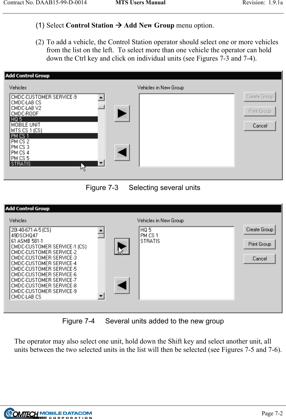
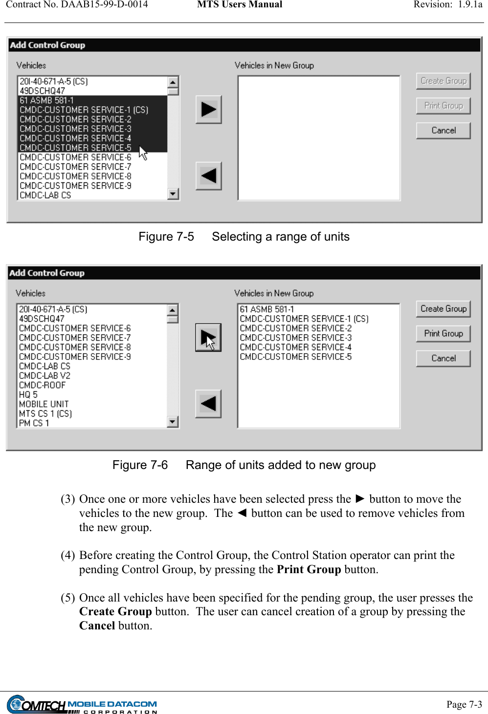
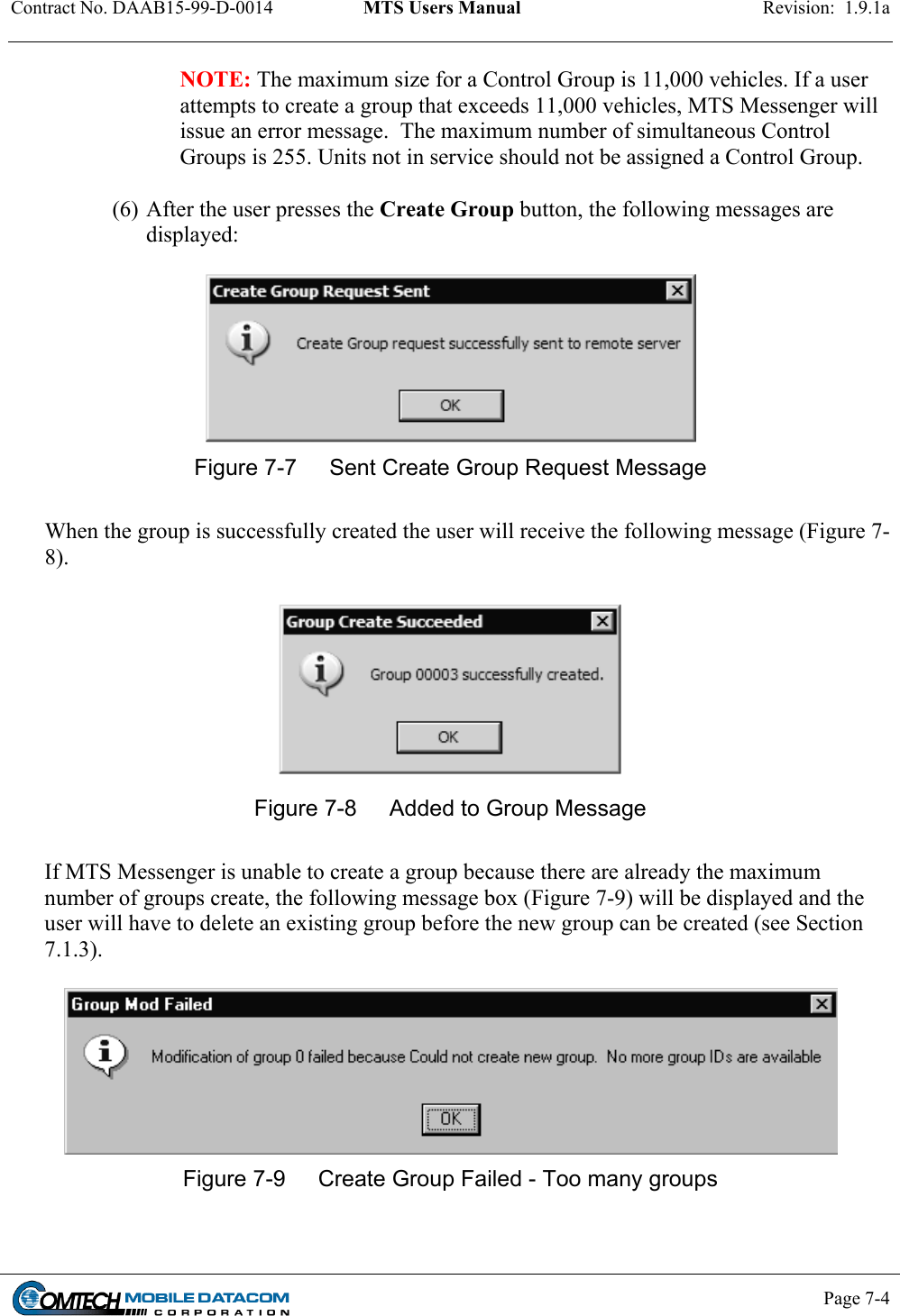
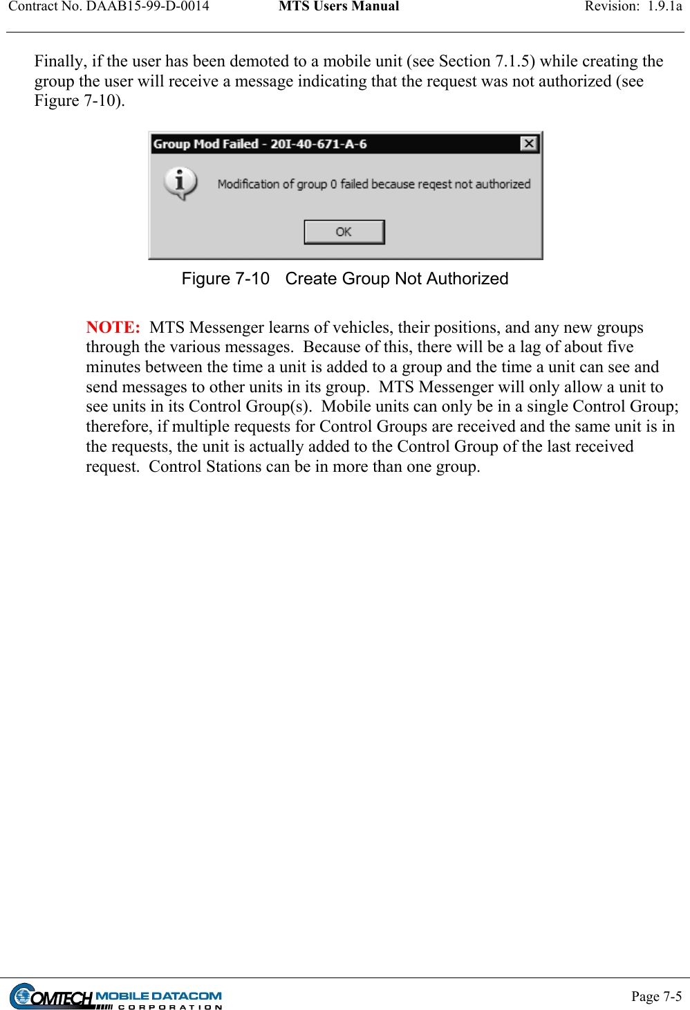
Comtech EF Data MTSMUV2MT2011 Satellite Modem User Manual MTS User s Manual
Comtech EF Data Satellite Modem MTS User s Manual
UserManual.wiki
>
Comtech EF Data
>
MTSMUV2MT2011 User Manual
>
manual1 1half
Contents
1.
manual1 1half
2.
manual2 2nd half
3.
manual3 3rd half
4.
manual4 4th half
5.
manual5 5th half
manual1 1half
Navigation menu
Upload a User Manual
Namespaces
Wiki Guide
HTML
PDF
Info
Views
User Manual
Discussion / Help
Navigation
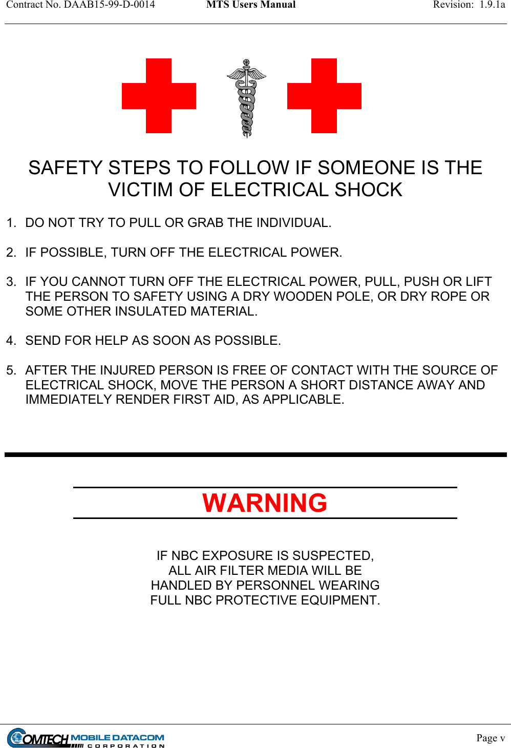


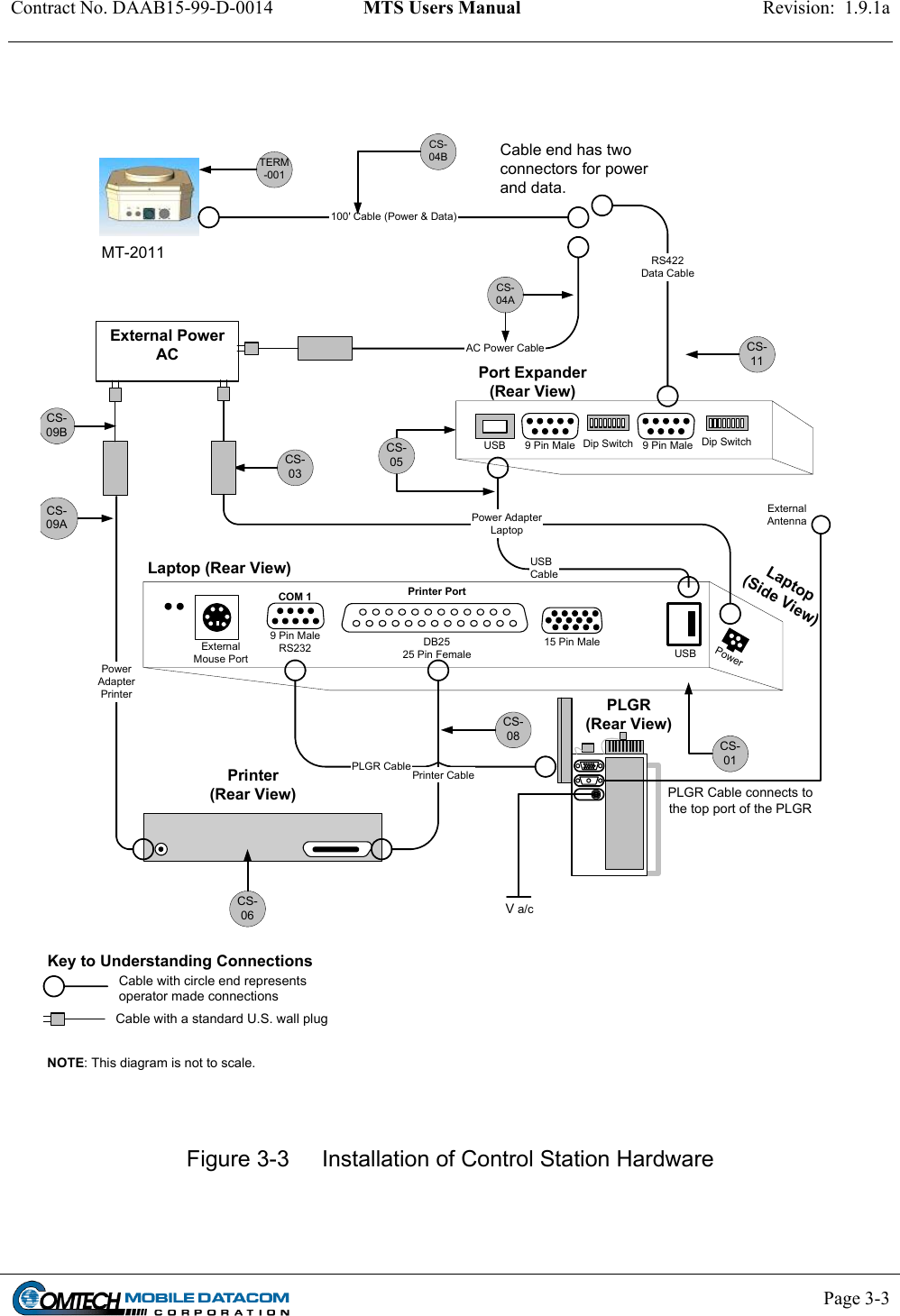
![Contract No. DAAB15-99-D-0014 MTS Users Manual Revision: 1.9.1a Page 3-4 3.2.2 Control Station (CS) Component Installation (See Figure 3-3) NOTE: Numbers in square brackets [#] denote part numbers in Figure 3-3. CAUTION: Do not force any connectors. Doing so may damage pins. 3.2.2.1 CS Transceiver (MT 2011) installation (1) Place the MT 2011 [TERM-001] in a location with a clear view of the sky, avoiding blockage or shadowing from trees and buildings. (2) Connect the 100-foot power/data cable [CS-04B] from the side of the transceiver to the RS-422 cable [CS-11] and the power cable [CS-4A]. 3.2.2.2 CS Laptop installation (1) Using the USB Cable [CS-05B] connect the USB port on the laptop [CS-01] to the USB port on the port expander [CS-05A]. The Port Expander should already be fastened to the laptop with Velcro. If it has become detached, refasten the port expander to the laptop. (2) Using the RS422 data cable [CS-11], connect the port expander [CS-05A] to the 100’ cable [CS-04B]. Connect one end of the cable to the 9 Pin Male port labeled COM3 on the port expander device [CS-05A] and connect the other end to the RS422 port on the 100’ cable [CS-04B]. (3) Connect the laptop power adapter [CS-03] to an AC power source. The power port on the laptop can be found on left side rear of the laptop. It does not need to be connected to the same AC power source as the Transceiver. NOTE: The laptop can work on internal batteries for up to four hours per battery. 3.2.2.3 CS Printer installation (1) Using the printer cable [CS-08] connect the printer to the laptop. One end of the cable will have a connector with a set of 25 pins; connect this end to the DB25 port (the large 25 pin port) on the rear of the laptop. Connect the other end of the cable to the printer. (2) Using the printer power adapter [CS-09A & CS-09B] and printer cable connect the printer to an AC power supply.](https://usermanual.wiki/Comtech-EF-Data/MTSMUV2MT2011.manual1-1half/User-Guide-419426-Page-23.png)
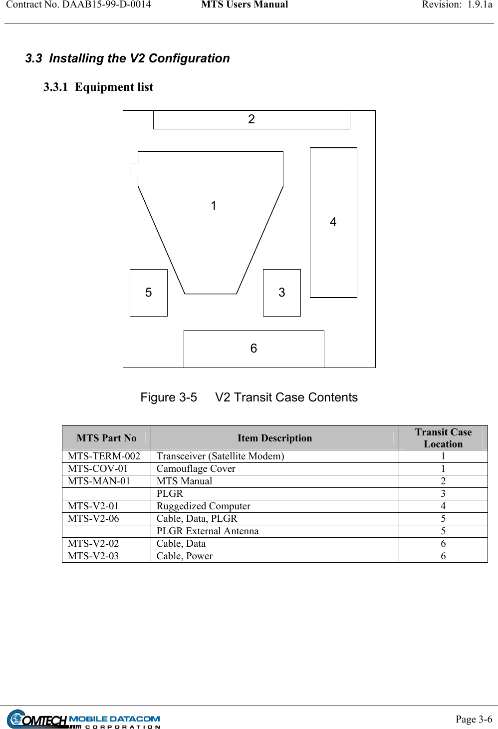
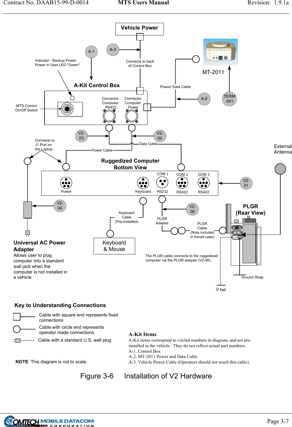
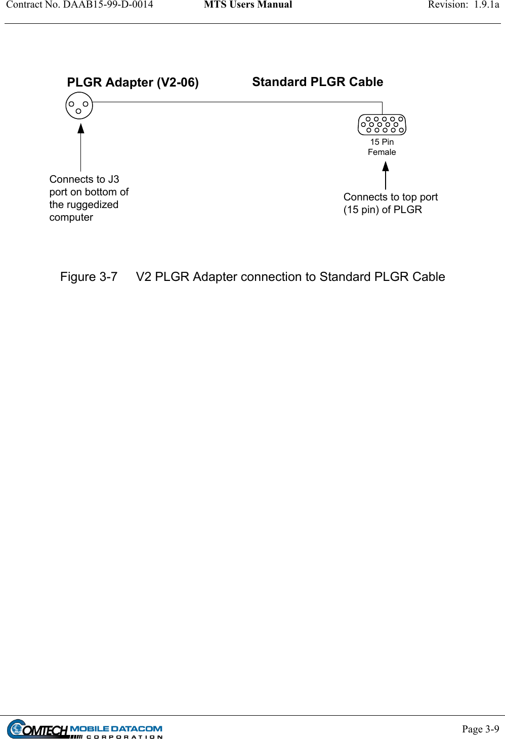
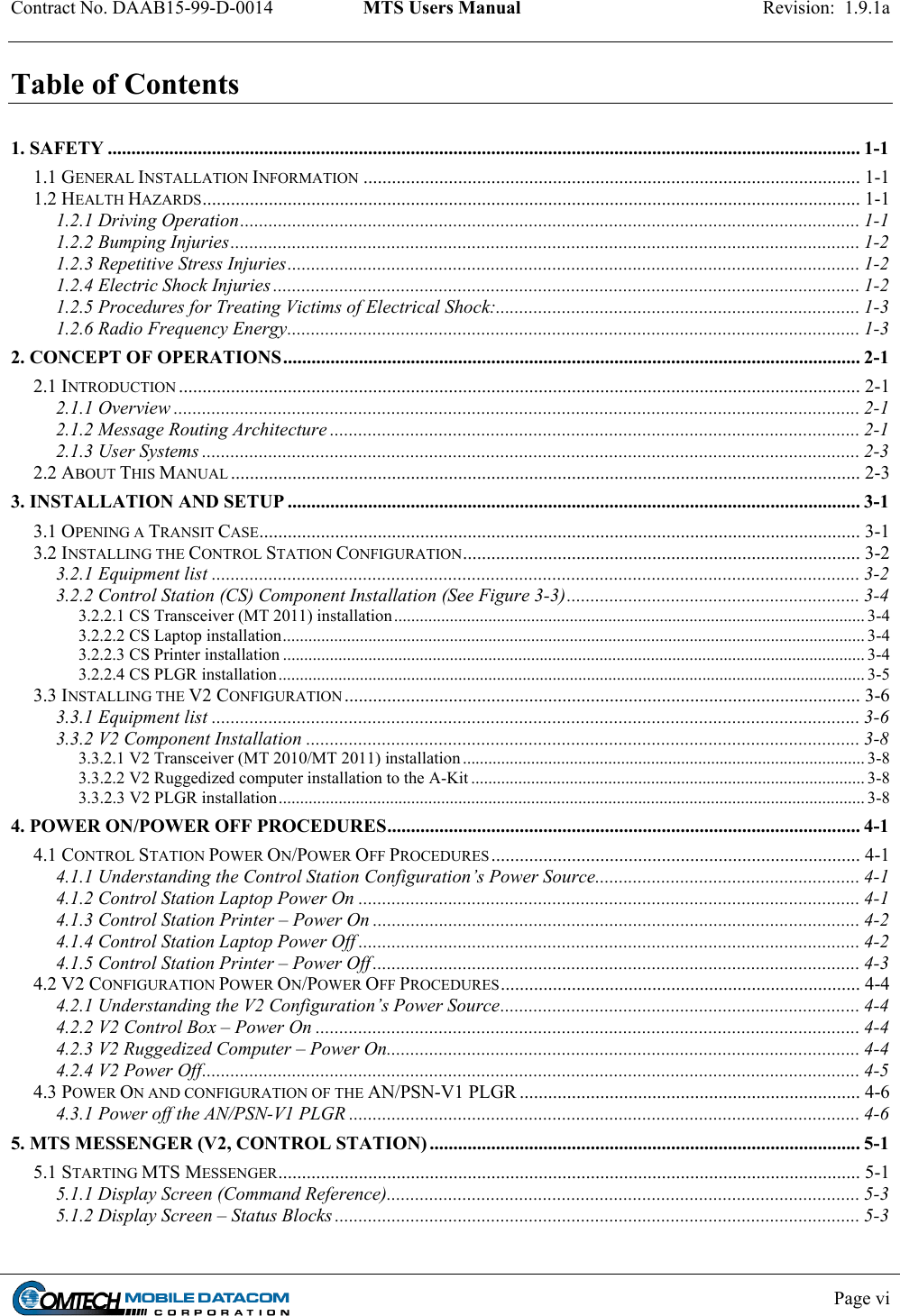
![Contract No. DAAB15-99-D-0014 MTS Users Manual Revision: 1.9.1a Page 3-8 3.3.2 V2 Component Installation NOTE: These installation instructions assume that the vehicle has already been configured with an A-Kit. Numbers in square brackets [#] denote part numbers in Figure 3-6. CAUTION: Do not force connections. Doing so may damage pins. 3.3.2.1 V2 Transceiver (MT 2010/MT 2011) installation (1) Attach the transceiver [TERM-001] to the A-Kit mounting bracket on the roof of the vehicle. (2) Attach the security lanyard found on the mounting bracket to the transceiver [TERM-001]. (3) Connect the A-Kit power/data cable [A-2] to the transceiver. The power/data cable is part of the A-Kit. It starts at the Control Box [A-1] and ends with a connector that attaches to the transceiver. When the transceiver is not mounted on the vehicle, the power/data cable connector should be securely stowed on the A-Kit mounting bracket to protect the cable connector. 3.3.2.2 V2 Ruggedized computer installation to the A-Kit (1) Attach the ruggedized computer [V2-01] to the A-Kit mounting bracket located inside vehicle. (2) Connect the data cable [V2-03] to COM 2 that is on the bottom side of the computer to the RS422 port on the A-Kit’s Control Box [A-1]. (3) Using the computer power cable [V2-02] connect the power port on the computer to the power port on the A-Kit’s Control Box [A-1]. 3.3.2.3 V2 PLGR installation (1) Connect the military connector on the PLGR adapter cable [V2-06] to the ruggedized computer’s [V2-01] serial port COM 1. Figure 3-7 shows the connectors on the PLGR adapter cable [V2-06]. (2) Connect the 9 pin male connector on the PLGR adapter cable [V2-06] to the 9 pin female connector on the PLGR cable. (3) Connect the 15 pin female connector of the PLGR cable to the top port of the PLGR. All ports on the PLGR can be found on the back of the device.](https://usermanual.wiki/Comtech-EF-Data/MTSMUV2MT2011.manual1-1half/User-Guide-419426-Page-27.png)