Compex Systems WPJ344 WIRELESS ACCESS POINT User Manual ah
Compex Systems Pte Ltd WIRELESS ACCESS POINT ah
UserManual.wiki
>
Compex Systems
>
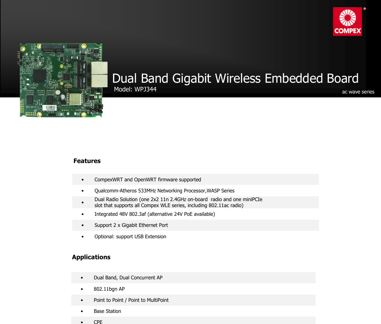
WPJ344 User Manual
users manual
Navigation menu
Upload a User Manual
Namespaces
Wiki Guide
HTML
PDF
Info
Views
User Manual
Discussion / Help
Navigation
![Technical Specifications System Information Processor Qualcomm-Atheros AR9344 MIPS 74Kc System Memory 128MB(64*2) DDR2 NOR Flash 8MB (max 16MB optional)1 MiniPCI Slot 1 x 9.2mm MiniPCIe slot Ethernet 2 Gigabit ports with Auto-MDI/X Extras Serial Port2, JTAG3, Reset Button, Surge Arrestor, Watchdog Timer Power Solutions High voltage DC Jack Input:24-48V, Passive PoE: 24-48V, IEEE 802.3af/at PoE Standard 802.3af PoE input:(Optional)4 Low voltage DC Jack Input: 9-24V, Passive PoE: 12-24V Power Consumption 7W RoHS Compliance Yes Humidity Operating: 5% to 95% (non-condensing) Storage: Max.90% (non-condensing) Temperature Range Operating:-20ºC to 70ºC Storage: -40ºC to 90ºC Dimension 117 x 105 x 17 (mm) 2.4GHz On-board Radio Transmit Power Data Rate Aggregate Power 1M 25dBm 11M 23dBm 6M 25dBm 54M 22dBm HT20 MCS0 25dBm HT20 MCS7 22dBm HT40 MCS0 25dBm HT40 MCS7 22dBm Receiver Sensitivity Data Rate 6M -90dBm 54M -75dBm HT20 MCS0 -90dBm HT20 MCS7 -72dBm HT40 MCS0 -88dBm HT40 MCS7 -70dBm Max of concurrent associations Encryption Client Latency TCP [each client upload and download randomly from 384Kbps to 768Kbps] UDP [each client upload and download 2Mbps] WPA2-PSK <100ms Single radio Dual radio Single radio Dual radio 40 clients 70clients (35 per radio) 20 clients 30clients (15 per radio) 1 Depends on Order Configurations 2 Serial Port is a 4-pin header (TTL) + Serial Converter is available to change the TTL signals on board to RS232 signals for debugging.Configurations are subjec to change without notification 3 JTAG Port is a 14-pin header + JTAG kit is for writing your own developed loader and firmware directly 4 In this mode, it can be powered from 802.3af/3at PoE switches and PoE injectors. It is able to return a PD classification of 0. The DC jack can accept a voltage range of 24V to 56V but the PoE input needs a minimum voltage of 36V](https://usermanual.wiki/Compex-Systems/WPJ344/User-Guide-2366458-Page-2.png)