Compex Systems 08-NP25G Wireless-G Internet Router User Manual Np25 manual
Compex Systems Pte Ltd Wireless-G Internet Router Np25 manual
UserManual.wiki
>
Compex Systems
>
08 NP25G User Manual
manual
Navigation menu
Upload a User Manual
Namespaces
Wiki Guide
HTML
PDF
Info
Views
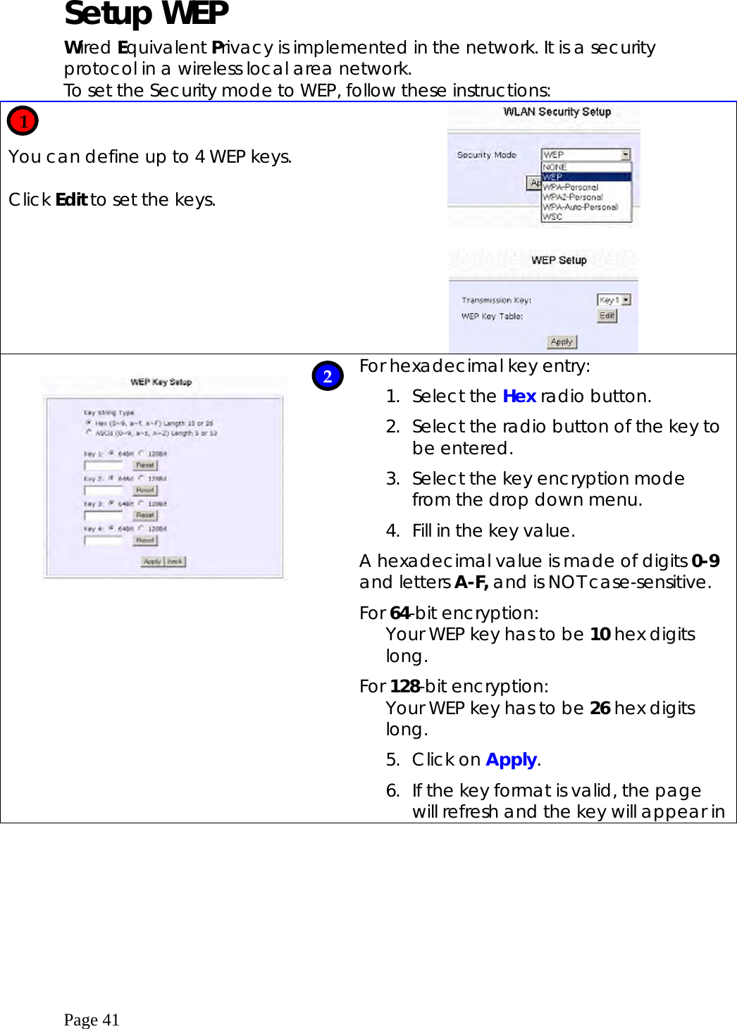
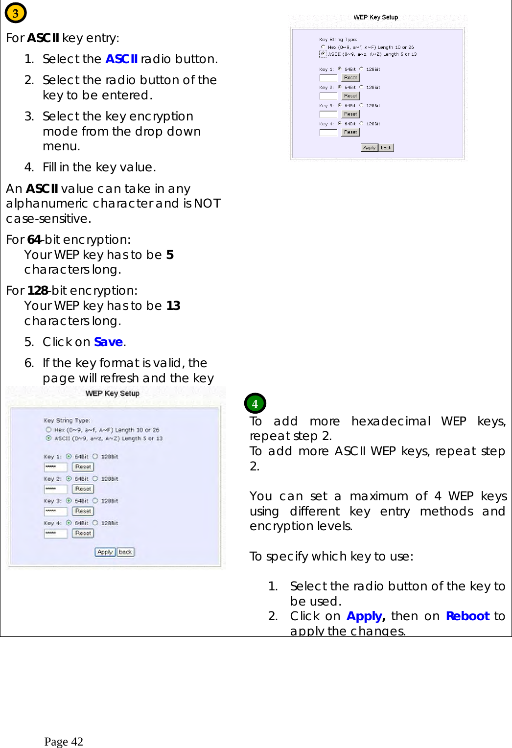
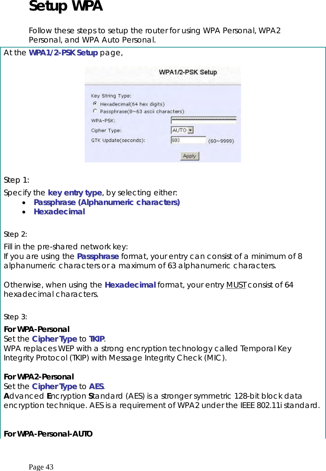
User Manual
Discussion / Help
Navigation