Cobham Surveillance Segensworth SOL7HDNTX SOLO 7 HD Nano Transmitter User Manual Solo7 Nano Transmitter
Cobham Surveillance Segensworth SOLO 7 HD Nano Transmitter Solo7 Nano Transmitter
UserManual.wiki
>
Cobham Surveillance Segensworth
>
SOL7HDNTX User Manual
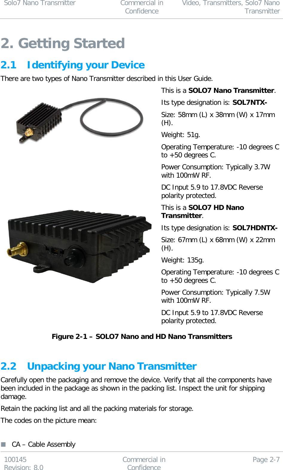
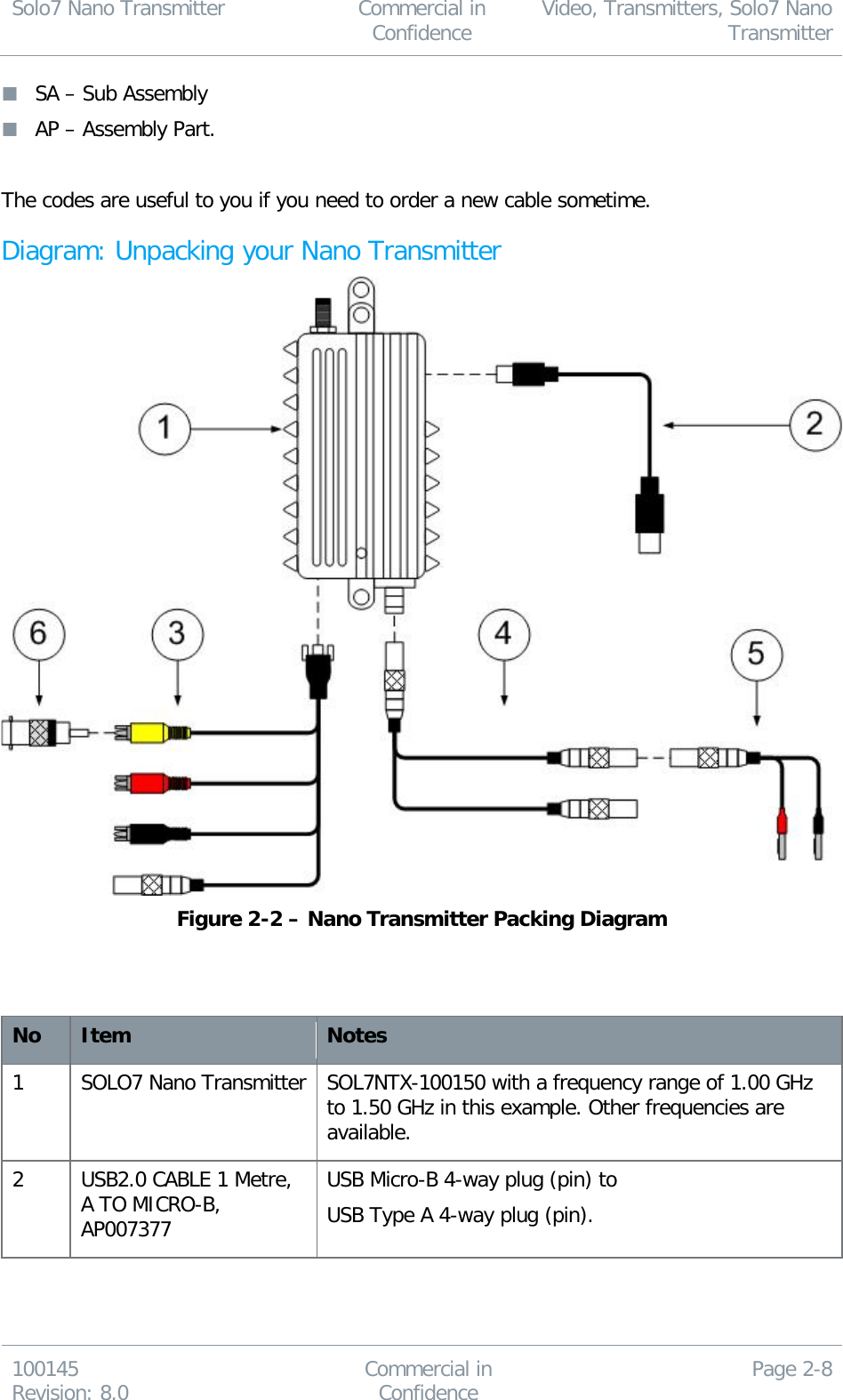
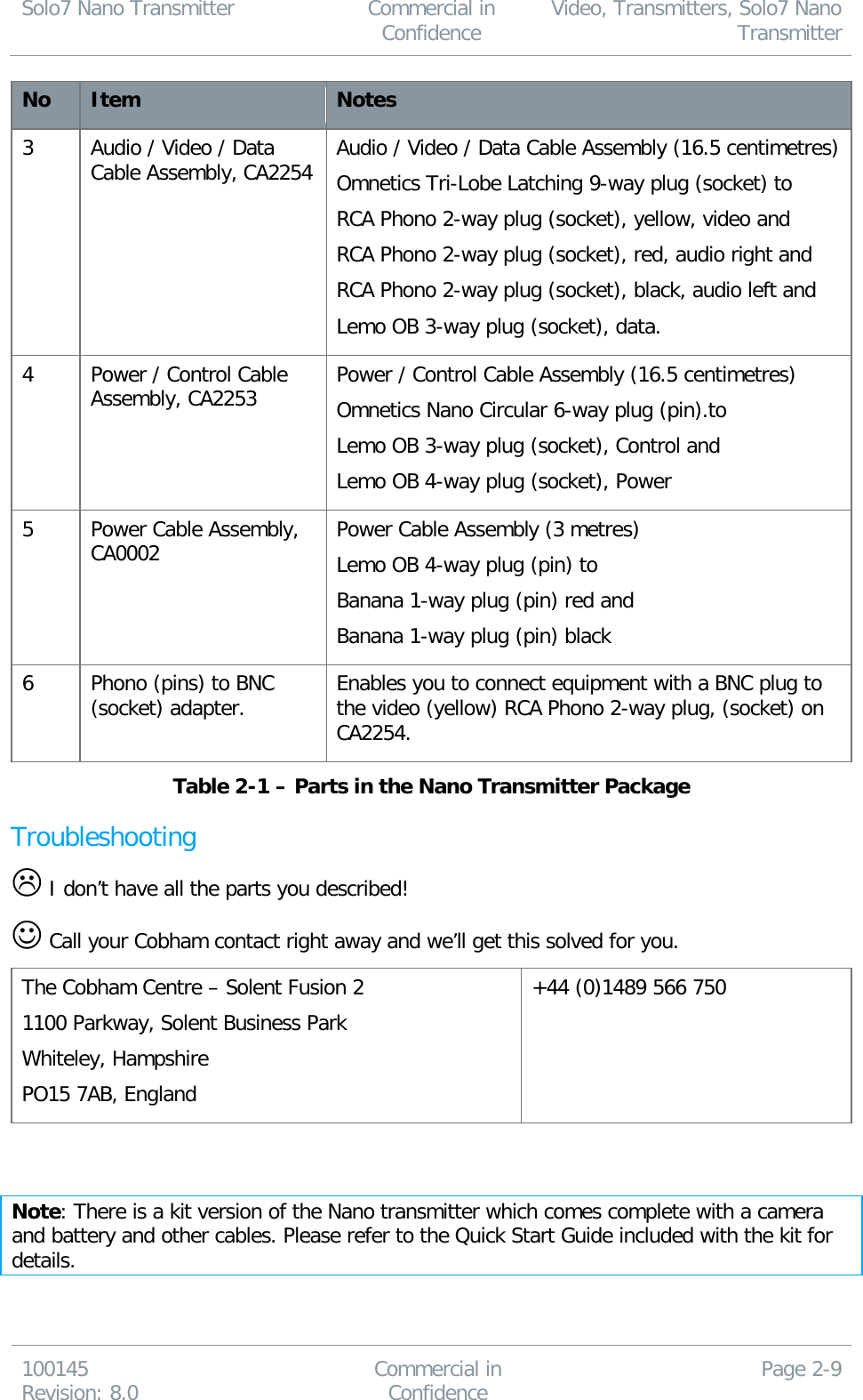
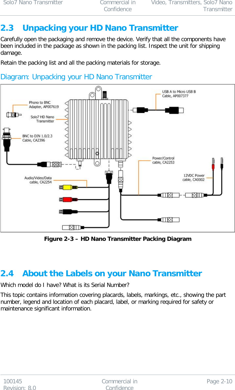
Solo7 Nano Transmitter User Guide
Navigation menu
Upload a User Manual
Namespaces
Wiki Guide
HTML
PDF
Info
Views
User Manual
Discussion / Help
Navigation
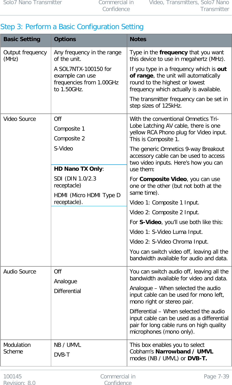
![Solo7 Nano Transmitter Commercial in Confidence Video, Transmitters, Solo7 Nano Transmitter 100145 Revision: 8.0 Commercial in Confidence Page 0-2 0.6 Typographic Conventions This document uses these typographic conventions to identify text that has a special meaning: Typographic Convention Example TEXT in small capitals represents a specific key press on the console keyboard or hardware panel. ESC, F1, SHIFT The + sign means “hold down the first key while pressing the second key”. Press CTRL+C to abort <Text> Serves as a placeholder for variable text that you will replace as appropriate to its context. Use the filename <systemname>.sys for… Text in bold emphasises a new word or term of significance. We call this a protocol and its function is… [-a] Text in these brackets indicates an optional component that can be left out. Ls [-a] NN This indicates a value entered on a numeric keypad. 45 on the numeric keypad Successive menu selections are shown using arrows to indicate a sub-menu. In this example this would mean: Select the Insert menu, then select picture, then select from file. Insert > picture > from file 0.7 Symbols This document uses these symbols to highlight important information: WARNING: A written notice given to a reader when a situation might result in personal injury or loss of life. CAUTION: A written notice given when a situation might result in damage to or destruction of equipment or systems. Note: A written notice given to draw the reader’s attention to something or to supply additional information.](https://usermanual.wiki/Cobham-Surveillance-Segensworth/SOL7HDNTX/User-Guide-2517566-Page-3.png)
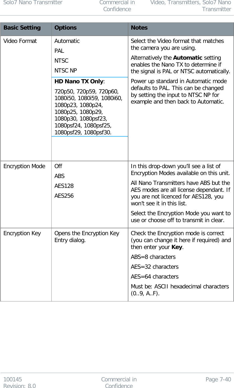
![Solo7 Nano Transmitter Commercial in Confidence Video, Transmitters, Solo7 Nano Transmitter 100145 Revision: 8.0 Commercial in Confidence Page 7-50 Step 5: Interpret the Licensed Features Settings Screenshot: Licensed Features Settings No Name Options Notes 1 Licensed Features Any license which is available for the Nano Transmitter. Licenses are given letter codes in square brackets [A] and a note of what that license does, SOLO2.5MHz Modulation for example. Codes shown in the Licensed Features group box are loaded on your device and all these features are available to use. 2 Unlicensed Features Any license which is available for the Nano Transmitter. Codes shown in the Unlicensed Features group box are available for the Nano Transmitter, but have not been purchased for your device yet. To load new licenses see Appendix D, Reference Material. Table 7-8 – Licensed Features Key](https://usermanual.wiki/Cobham-Surveillance-Segensworth/SOL7HDNTX/User-Guide-2517566-Page-57.png)