Cisco Linksys BEFW11S4V32 Wireless Access Point Router with 4-Port Switch User Manual Part 1
Cisco-Linksys, LLC Wireless Access Point Router with 4-Port Switch Users Manual Part 1
Contents
- 1. DoC Statement
- 2. Users Manual Part 1
- 3. Users Manual Part 2
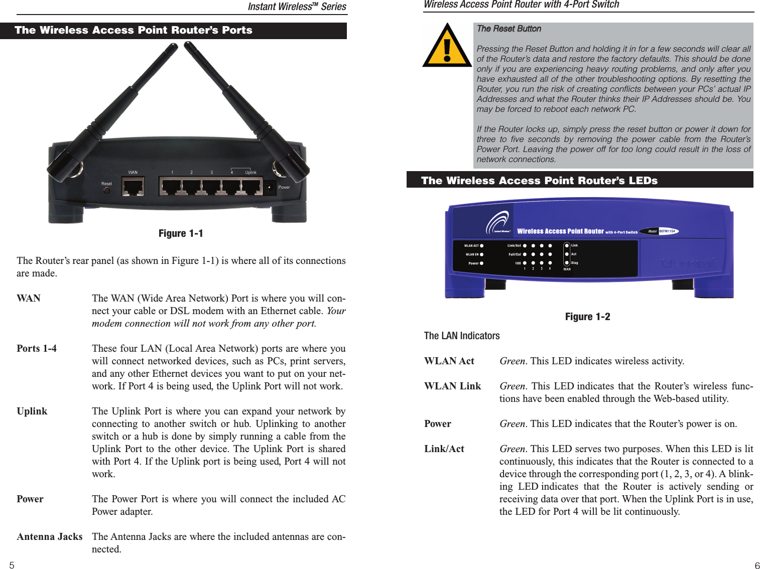
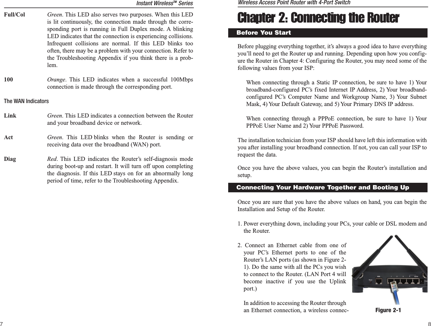
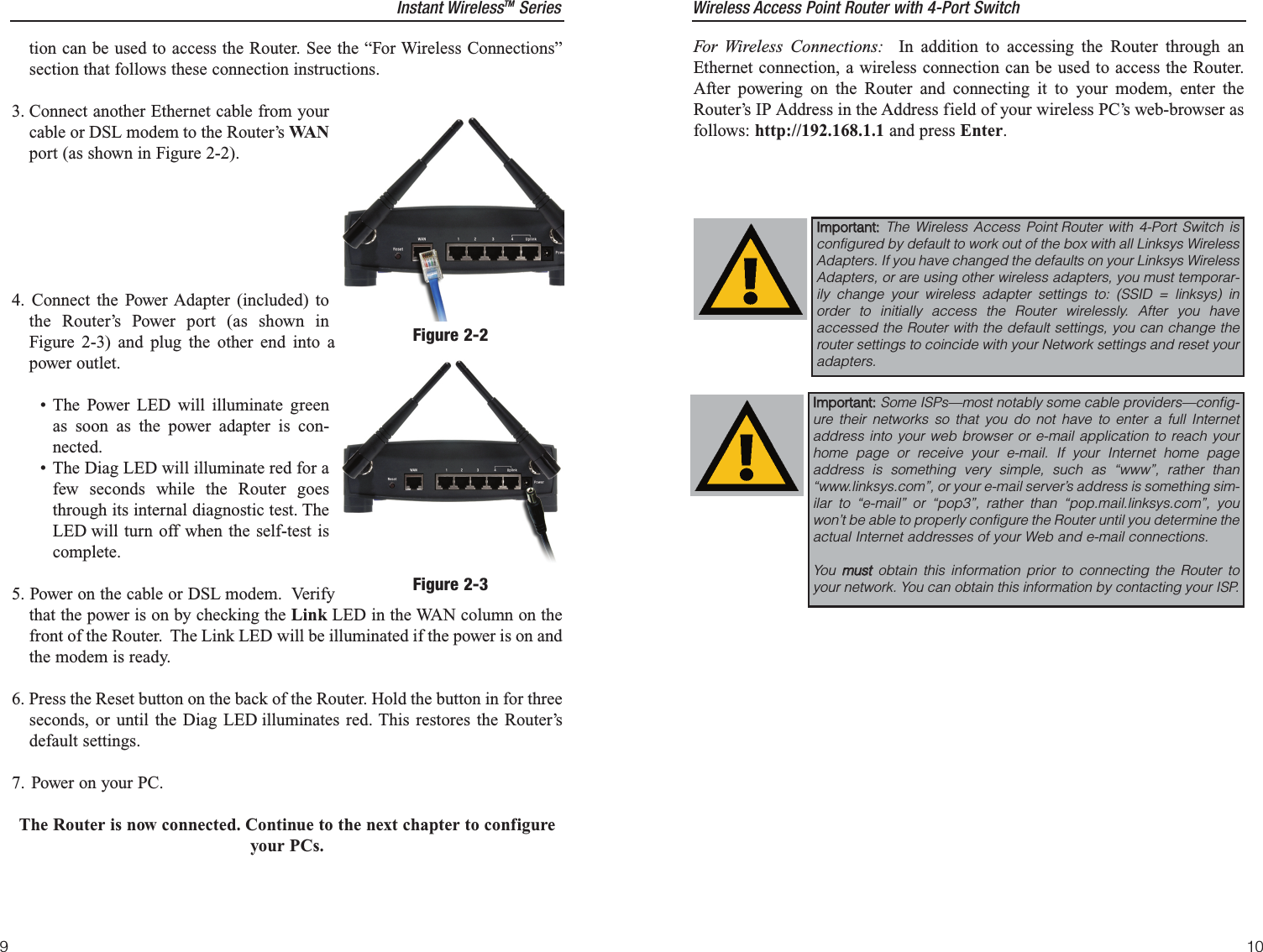
Users Manual Part 1