China Electric Manufacture DCM70-5B-2L Ceiling suspended fan User Manual Technical for fan
Hong Kong China Electric Manufacture Co., Ltd Ceiling suspended fan Technical for fan
UserManual.wiki
>
China Electric Manufacture
>
DCM70 5B 2L User Manual
users manual
Navigation menu
Upload a User Manual
Namespaces
Wiki Guide
HTML
PDF
Info
Views
User Manual
Discussion / Help
Navigation
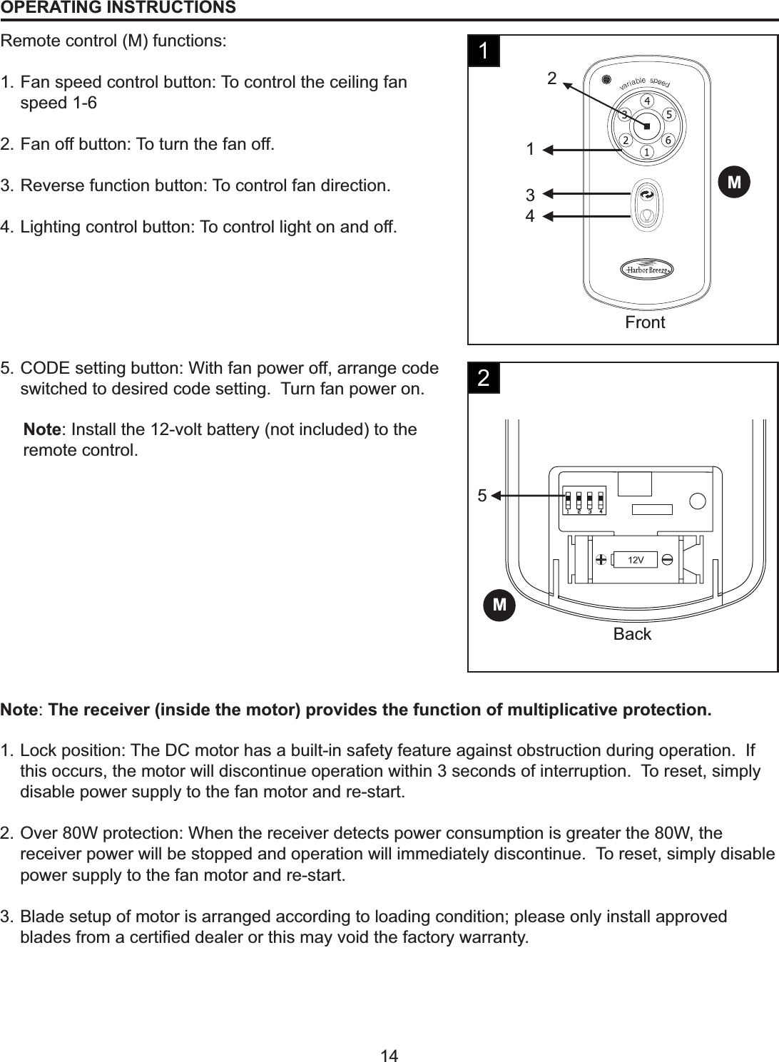
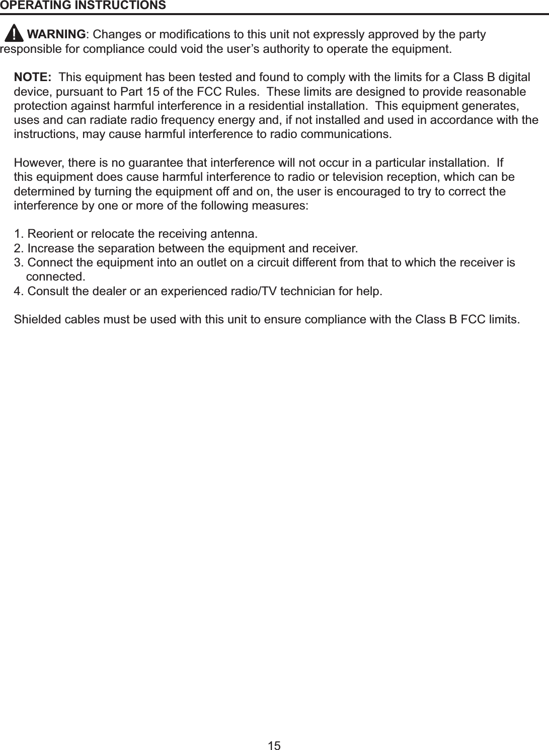
![7ASSEMBLY INSTRUCTIONS1. Turn off circuit breakers and wall switch to the fan supply line leads. [Fig. 1]2. Determine mounting methods to use. [Fig. 2]3. Check to make sure blades (H) will be at least 30 in. from any obstructions. Check downrod (A) length to HQVXUHEODGHV+DUHDWOHDVWIWDERYHWKHÀRRU[Fig. 3]Important: If using the angle mount, check to make sure the ceiling angle in not steeper than 25°DANGER: Failure to disconnect power supply prior to installation may result in serious injury or death.123](https://usermanual.wiki/China-Electric-Manufacture/DCM70-5B-2L/User-Guide-1525857-Page-7.png)
![CClip PinSetScrewEAAFBA8ASSEMBLY INSTRUCTIONS4. Secure mounting bracket (C) to outlet box using screws, VSULQJZDVKHUVDQGÀDWZDVKHUVSURYLGHGZLWKWKHRXWOHWbox (not included). [Fig. 4]Note:It is very important that you use the proper hardware when installing the mounting bracket (C) as this will support the fan.Important: If using the angle mount, make sure open end of mounting bracket (C) is installed facing the higher point of ceiling.5. Remove pin and clip from downrod (A). Partially loosen set screws in motor housing yoke at top of motor housing (E). [Fig. 5]Help Hint: Downrod style mounting is best suited for ceilings 8 ft. or higher. For taller ceilings you may want to use a longer downrod (not included). Angle style mounting is best suited for angled or vaulted ceilings.A longer downrod is sometimes necessary to ensure proper blade clearance.6. Insert downrod (A) through canopy (B) and yoke cover (F). Thread wires from motor housing (E) through downrod (A). [Fig. 6]456](https://usermanual.wiki/China-Electric-Manufacture/DCM70-5B-2L/User-Guide-1525857-Page-8.png)
![ClipPinFAEFABall9ASSEMBLY INSTRUCTIONS7. Slip downrod (A) into motor housing yoke, align holes and re-install pin and clip. Re-tighten set screws in motor housing yoke and then tighten nuts. Slide yoke cover (F) down until it rests on top of motor housing (E). [Fig. 7]8. Depending on the length of downrod (A) you use, you may need to cut the lead wires back to simplify the wiring. If you decide to cut back the lead wires, it is suggested that you do so in the following manner: Take the lead wires and make sure that you have pulled them all the way through the top of the downrod (A) and measure 8 in. of lead wire, and then cut the excess wire off with wire cutters. [Fig. 8]9. If you decided to cut back the lead wire in Step 9, strip 1/2 in. of insulation from end of white wire.Twist stripped ends of each strand of wire within the insulation with pliers. [Fig. 10] Repeat Step 10 for black, blue (if applicable) and green wires.Note: If you did not cut back the lead wires, Step 10 is not necessary and you may proceed to Step 11 instead.789](https://usermanual.wiki/China-Electric-Manufacture/DCM70-5B-2L/User-Guide-1525857-Page-9.png)
![FAN AND LIGHT CONTROLLED BY REMOTE CONTROL1. Connect BLACK wire from fan to BLACK wire from ceiling. Connect WHITE wire from fan to WHITE wire from ceiling. Connect all GROUND (GREEN) wires together from fan to BARE/GREEN wire from ceiling. [Fig. 1]Hardware UsedBallCBAREMOTE CONTROL10ASSEMBLY INSTRUCTIONS10. Install ball end of downrod (A) into mounting bracket (C) opening. Align slot in ball with tab in mounting bracket (C). [Fig. 10]DANGER: Failure to align slot in ball with tab may result in serious injury or death.101WIRINGWARNING7RUHGXFHWKHULVNRI¿UHHOHFWULFDOVKRFNRUSHUVRQDOLQMXU\ZLUHFRQQHFWRUVprovided with this fan are designed to accept only one 12-guage house wire and two lead wires from the fan. If your house wire is larger then 12 guages there is more than one house wire to connect to the two fan lead wires, consult an electrician for the proper size wire connectors to use.CAUTION: Be sure outlet box is properly grounded or that a ground (green or base) wire is present.WARNING: if house wires are different colors than refereed to in the following step, stop immediately. A professional electrician is recommended to determine wiring.Note: Please refer to installation and operating instructions for remote control.DD Wire connector x 4](https://usermanual.wiki/China-Electric-Manufacture/DCM70-5B-2L/User-Guide-1525857-Page-10.png)
![DDDDDDBAKBBHGCCH11WIRING2. Wrap electrical tape around each individual wire connector (DD) down to the wire as shown in Fig. 3. WARNING: Make sure no bare wire or wire strands are visible after making connections. Place green and white connections on opposite side of box from the black and blue (if applicable) connections.Turn spliced/taped wires upward and gently push wires and wire connector (DD) into outlet box.2FINAL INSTALLATION1. Tuck connections neatly into ceiling outlet box. Remove one screw from the mounting bracket (C) and loosen the other screw around 1/4 in.Align the canopy (B) up to ceiling and over the loose screw. Place the canopy (B) into key hole and rotate clockwise.Secure the canopy (B) with previously removed screw. Place the canopy cover (K) over the canopy (B) and rotate clockwise until it is locked into right position. [Fig. 1]12. Partially insert three blade screws (BB), along with three blade washers (CC) to attach one blade arm (G) to a blade (H). Then, tighten each blade screw (BB) starting with the one in the middle. [Fig. 2] Repeat with remaining blades (H). 2BBCCBlade Screw x 15Blade Washers x 15Hardware Used](https://usermanual.wiki/China-Electric-Manufacture/DCM70-5B-2L/User-Guide-1525857-Page-11.png)
![HGAALEScrewDE12FINAL INSTALLATION3. Insert two motor screws (AA), along with lock washers, through one blade arm, (G) to attach blade arm, (G) to motor. Tighten motor screws (AA) securely. [Fig. 3] Repeat with remaining blade arms (G), making sure to completely secure each blade arm (G) before proceeding with the next step.4. Remove one of the four screws from the motor assembly (E) and loosen the other three. Align the screw holes of the light kit plate (L) with the loosened screws and replace and tighten all screws.34AA Motor Screw x 10Hardware Used5. Remove one of the three screws from the light kit plate (L) and loosen other two. Connect the connectors from WKHOLJKWNLW¿WWHU'DQGIDQ$OLJQWKHVFUHZKROHVRIWKHOLJKWNLW¿WWHU'ZLWKWKHORRVHQHGVFUHZVDQGreplace and tighten all screws.5](https://usermanual.wiki/China-Electric-Manufacture/DCM70-5B-2L/User-Guide-1525857-Page-12.png)
![JID13FINAL INSTALLATION6. Install bulbs (J). [Fig. 6]Important: When you need to replace bulbs, please allow bulb (J) and light kit to cool down before touching the bulb (J) or the light kit.Note: fan uses two 13-watt max. GU24 bi-pin base CFL bulbs WARNING: The CFL bulbs contain mercury, discard then according to the local law.$WWDFKWKHJODVVVKDGH,WRWKHOLJKWNLW¿WWHU'E\twisting tightly.67](https://usermanual.wiki/China-Electric-Manufacture/DCM70-5B-2L/User-Guide-1525857-Page-13.png)