Carnegie Robotics 00068 Platform Module User Manual 56091197a English indd
Carnegie Robotics LLC Platform Module 56091197a English indd
UserManual.wiki
>
Carnegie Robotics
>
00068 User Manual
>
Operator Manual Part 2
Contents
1.
Operator Manual Part 1
2.
Operator Manual Part 2
Operator Manual Part 2
Navigation menu
Upload a User Manual
Namespaces
Wiki Guide
HTML
PDF
Info
Views
User Manual
Discussion / Help
Navigation
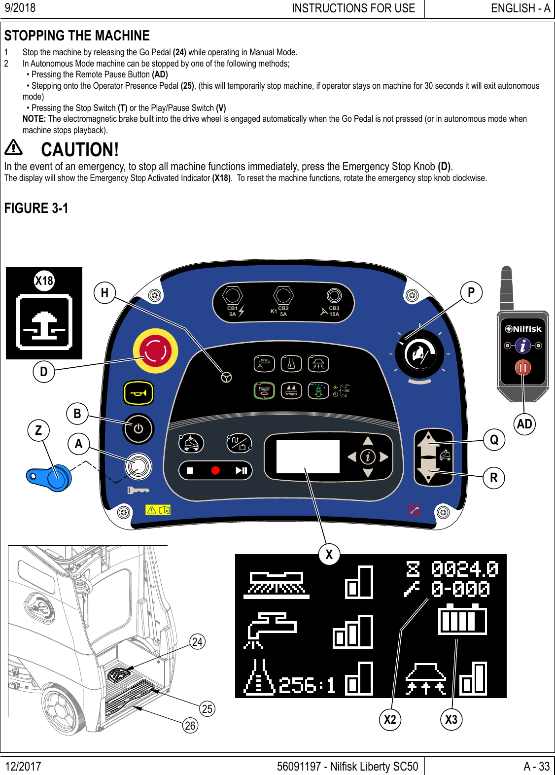
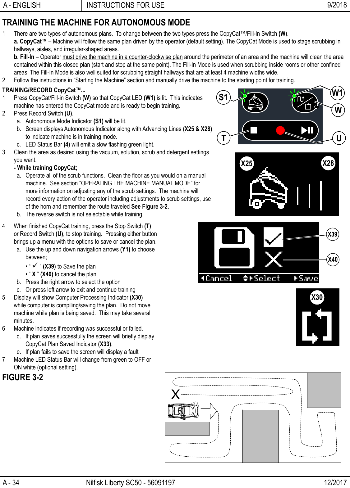
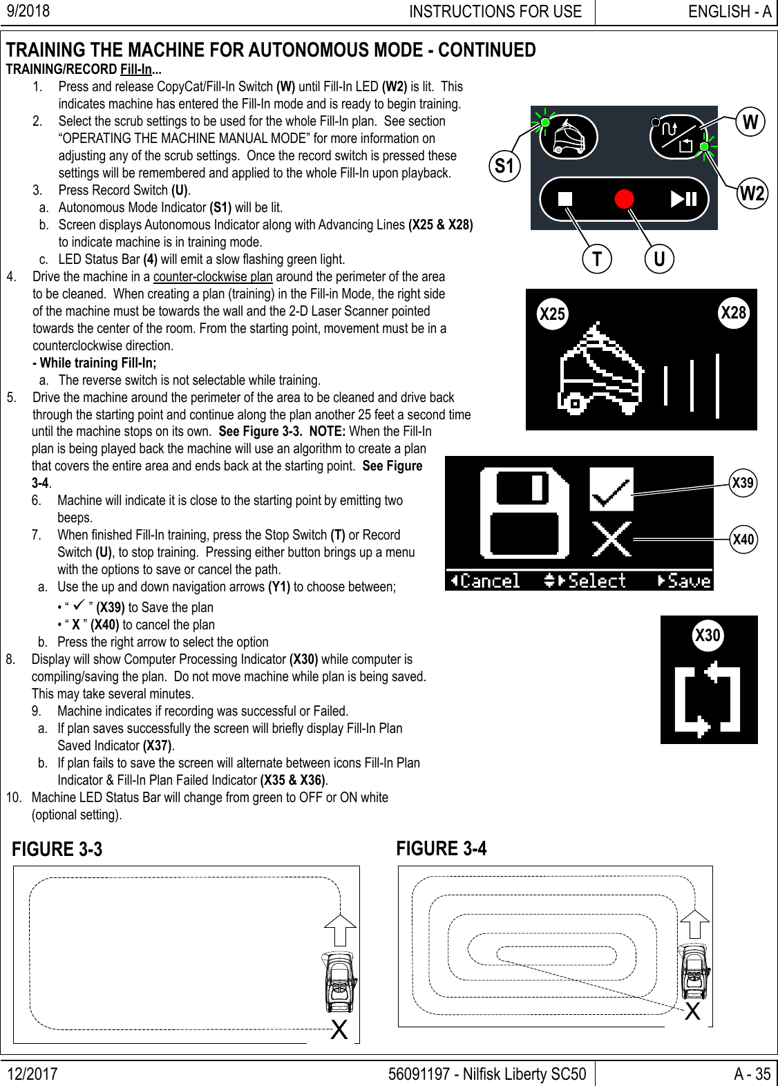
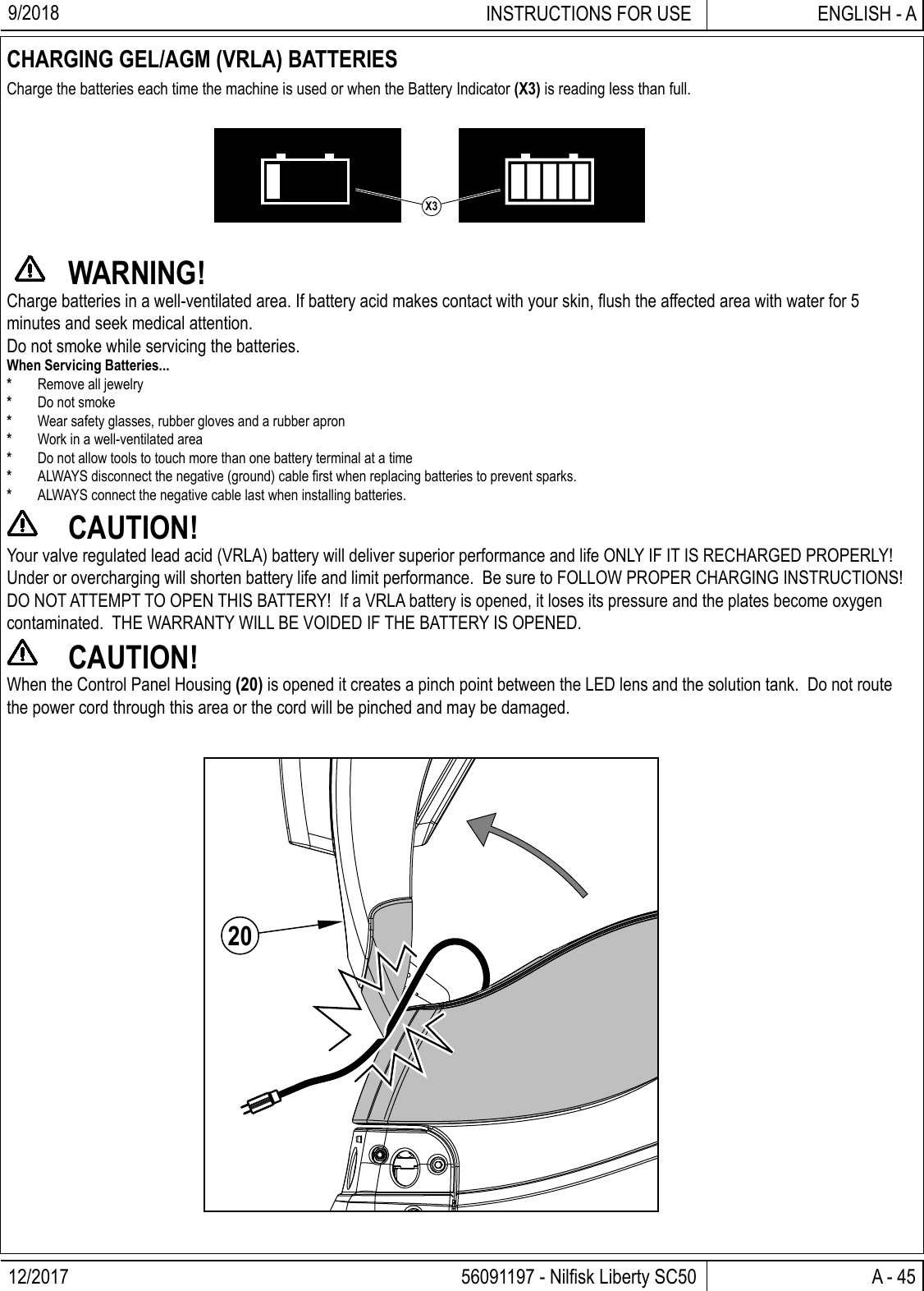
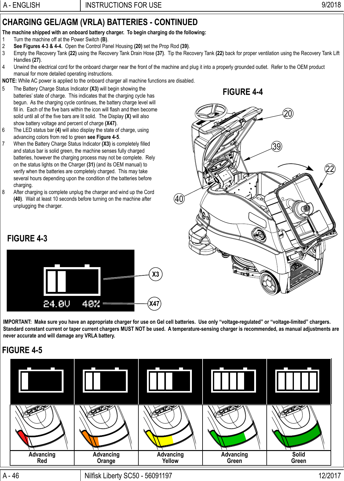
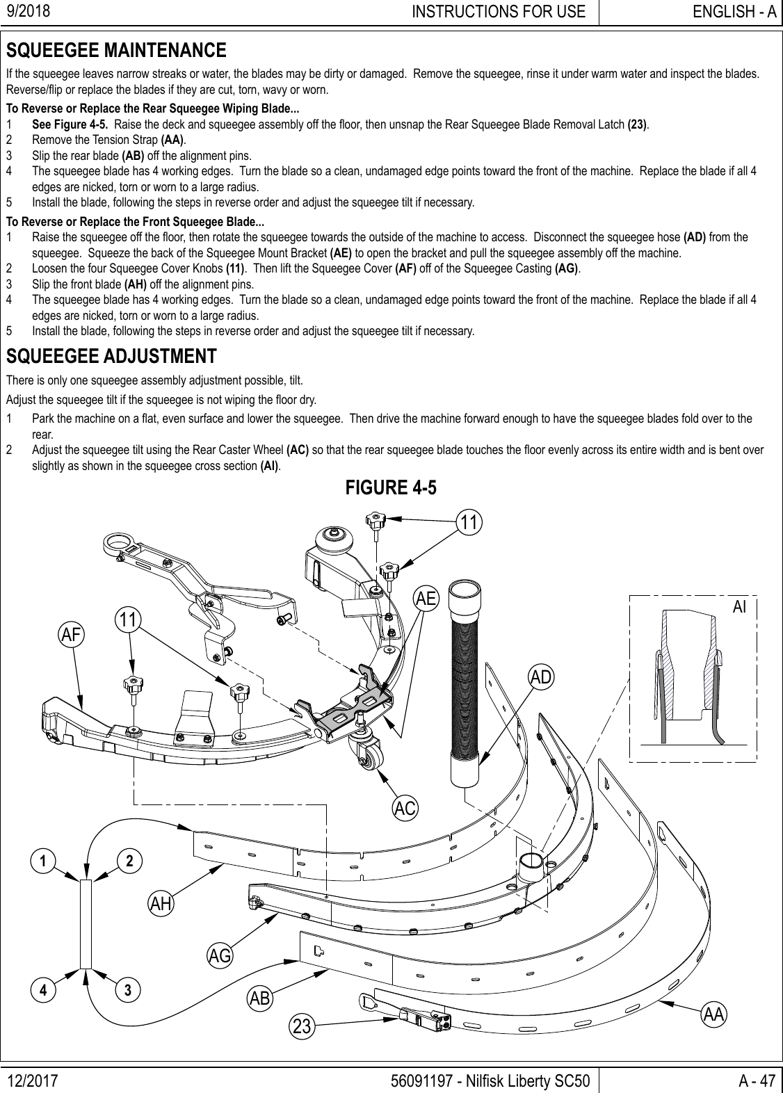
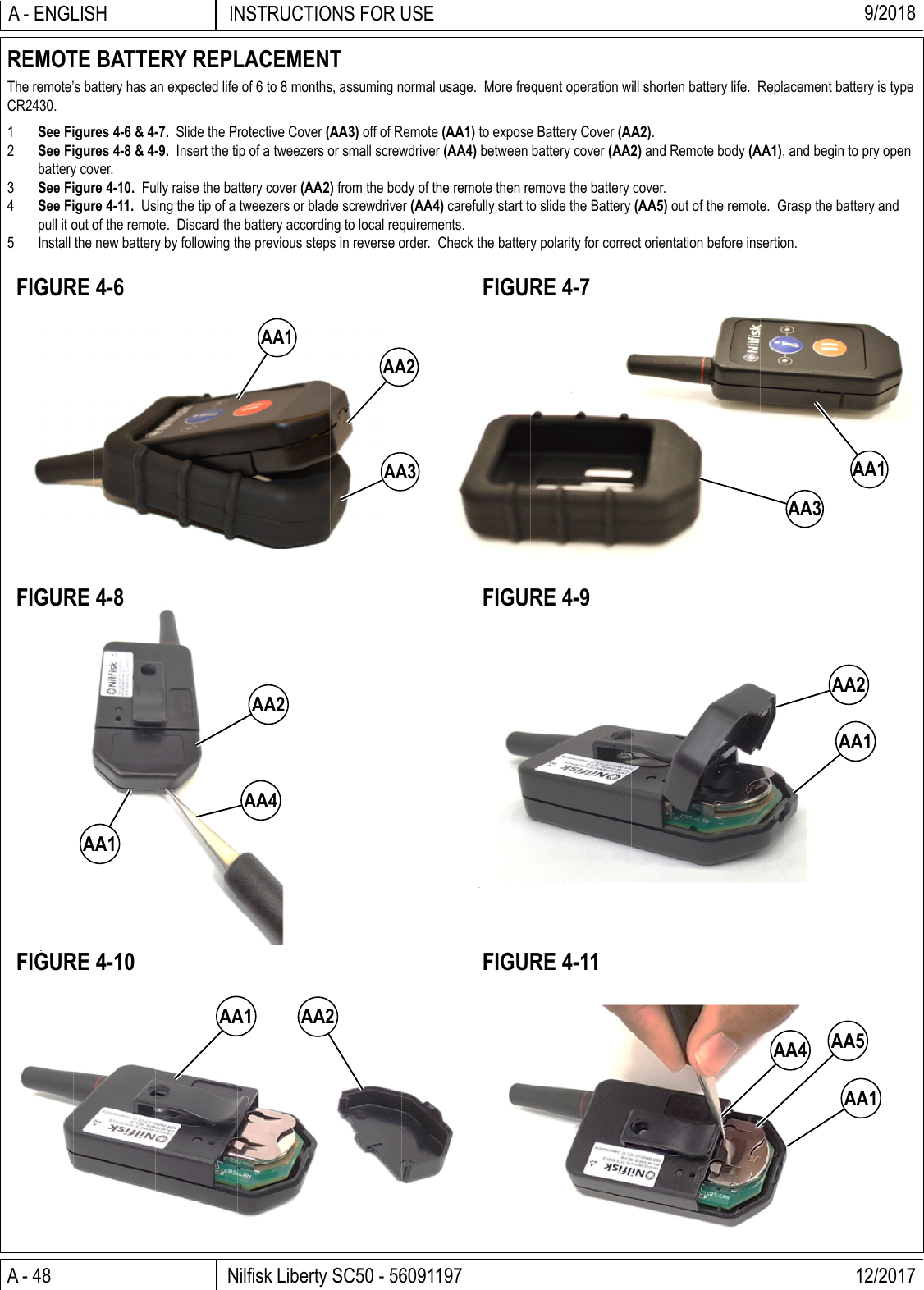
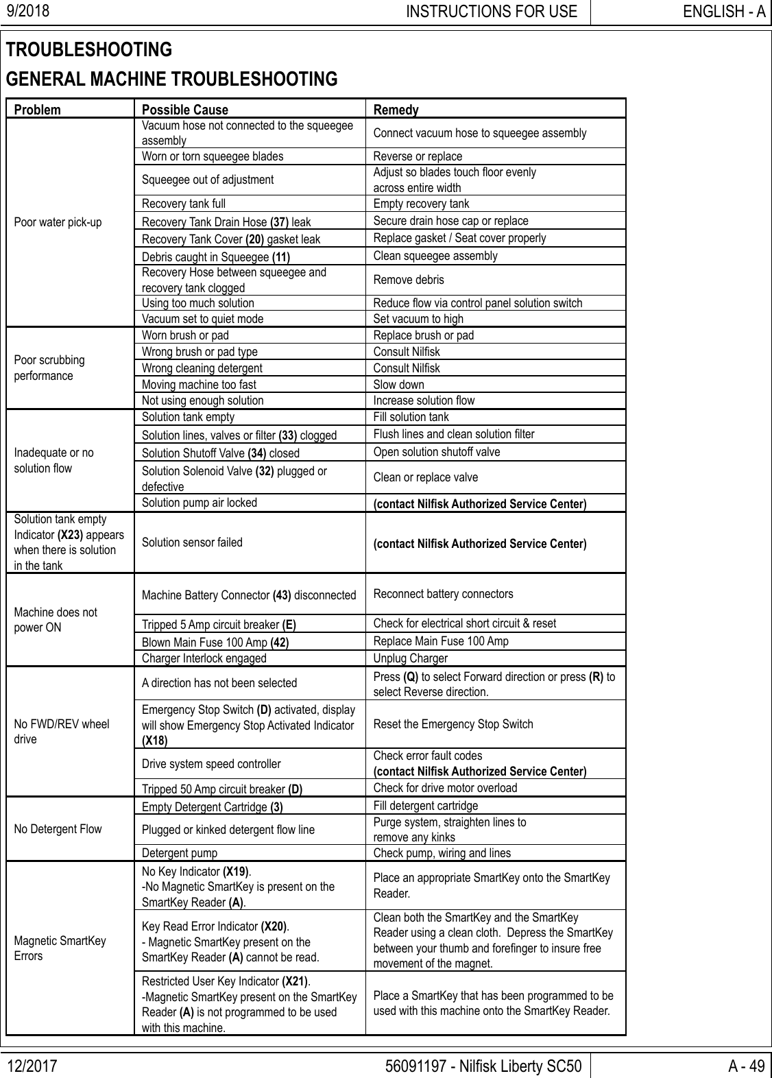
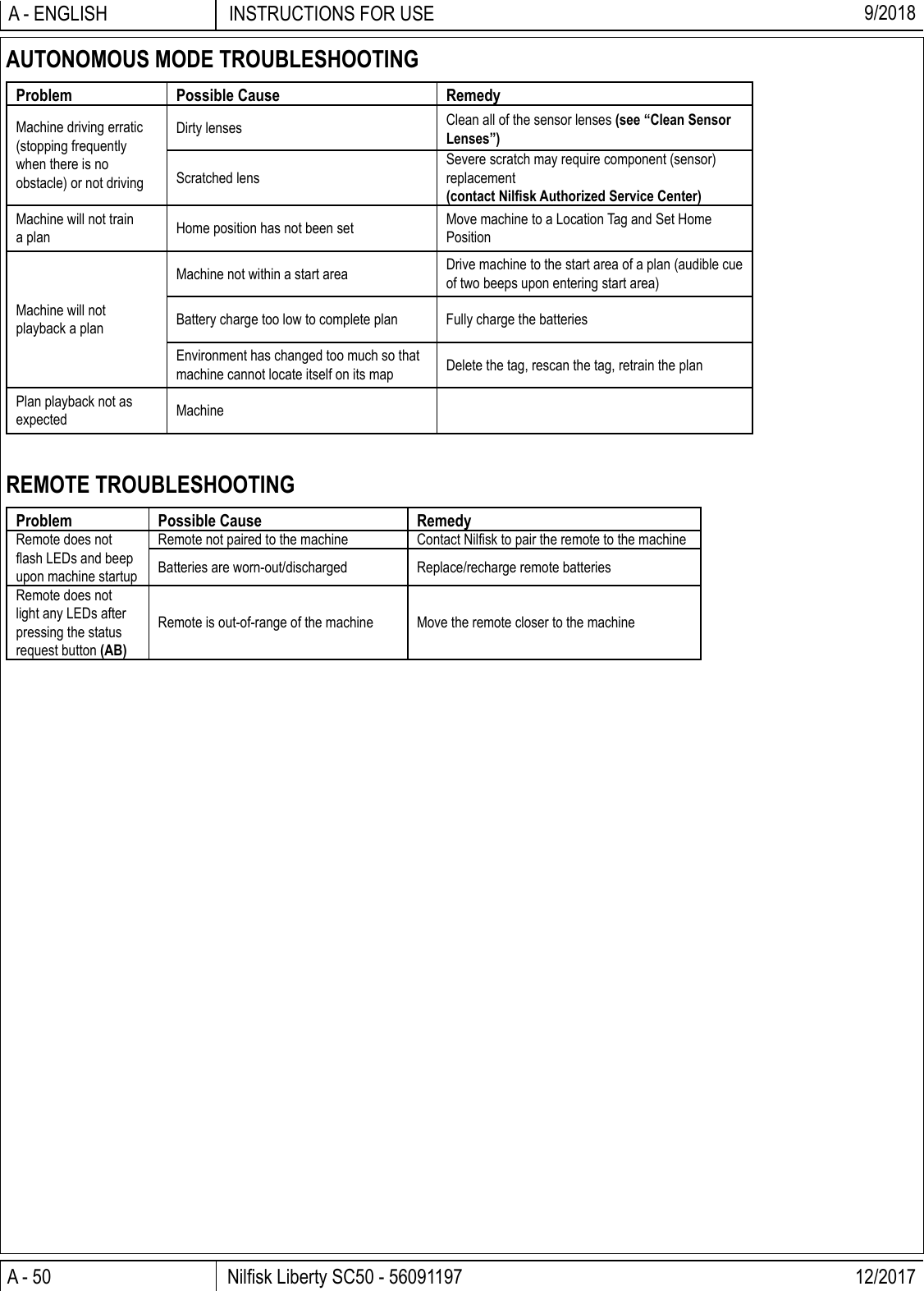
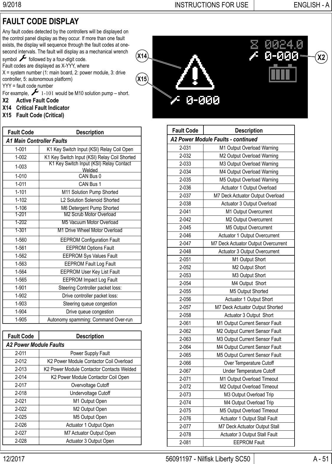
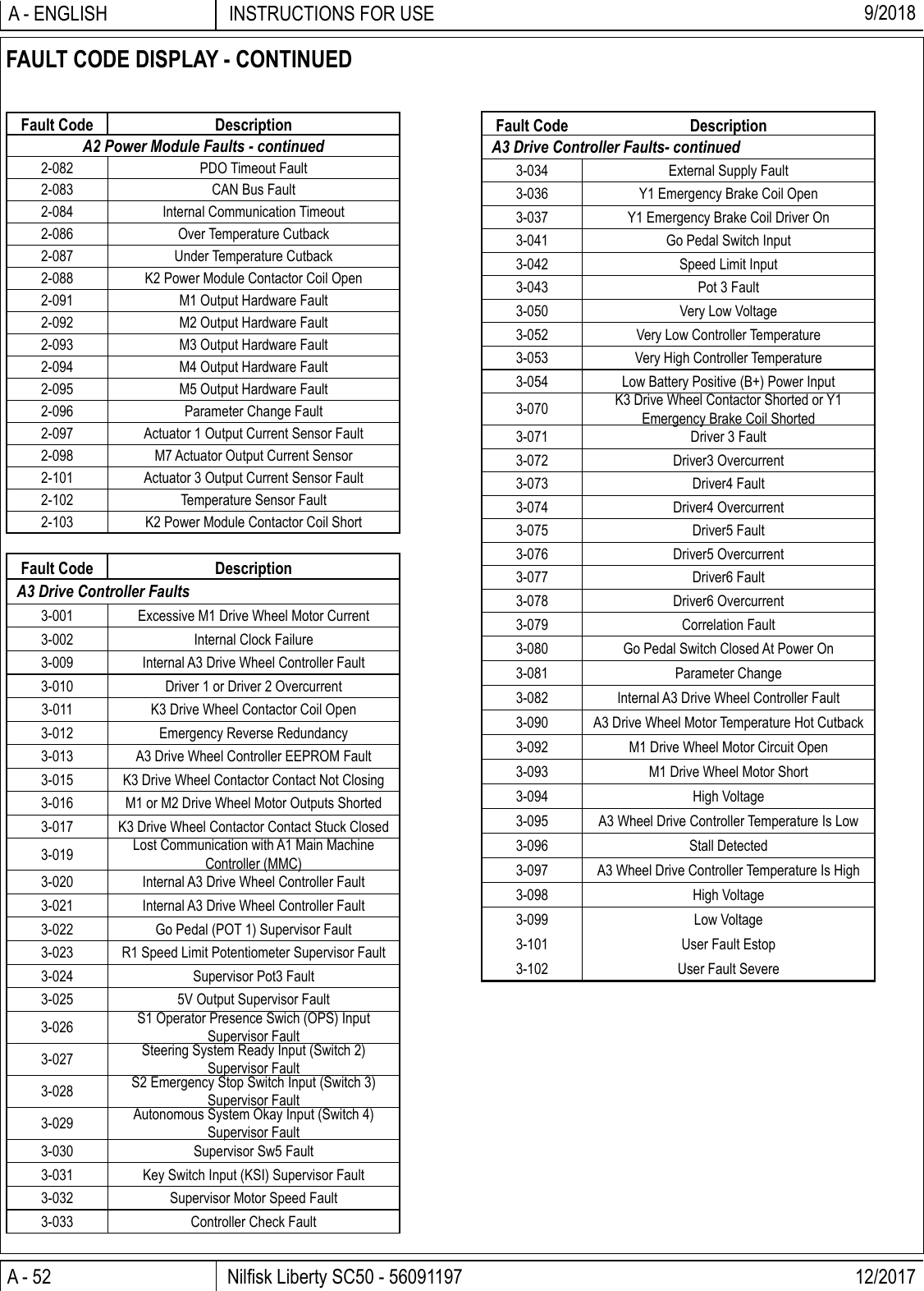
![A - 56 Nilfi sk Liberty SC50 - 56091197 12/2017INSTRUCTIONS FOR USEA - ENGLISH 9/2018FAULT CODE HISTORYEvery fault code that occurs is recorded by the machine and kept in a history log. See Figures 5-1 – 5-4. To view the fault history press the Information Switch (Y) to bring up the information menu. Use the four Navigation Arrows (Y1) (up, down, left & right) to move through the menu and the information switch to exit the menu.YMenuHoursFaultsKeysOptionsiExit Select Y1Y1FaultsActive Faults 0Fault History 5Back SelectFault History1-003 0007.7Back Select(1/5)3-001 0005.23-001 0005.23-001 0004.3Fault History1-003 0007.7Back Scroll(1/5)K1 Contact WeldScroll down to Faults, right arrow to select.Menu [Menu] ________________________________ Hours [Hours] Faults [Faults] Keys [Keys] Options [Options] _______________________Exit [i Exit] Select [Select]Scroll down to Fault History, right arrow to select.Faults [Faults] ______________________________ Active Faults [Active Faults] Fault History [Fault History] ___________________________________________ Back [Back] Select [Select]A list of all faults and corresponding timestamp will be displayed, scroll up or down to an individual fault, right arrow for more information.Fault History [Fault History] __________________ Fault code Drive Hours ___________________________________________ Back [Back] Select [Select]The fault is displayed along with the timestamp and description. Use the up and down arrows to scroll through the list of faults.Fault History [Fault History] _________________Fault Code Drive HoursFault Code Description ___________________________________________ Back [Back] Scroll [Scroll]FIGURE 5-1FIGURE 5-2FIGURE 5-3FIGURE 5-4](https://usermanual.wiki/Carnegie-Robotics/00068.Operator-Manual-Part-2/User-Guide-4054489-Page-26.png)