Carlson Wireless Technologies TB49 Trailblazer TB 4.9 User Manual TB UserManual 1 02
Carlson Wireless Technologies Inc Trailblazer TB 4.9 TB UserManual 1 02
UserManual.wiki
>
Carlson Wireless Technologies
>
TB49 User Manual
Users Manual
Navigation menu
Upload a User Manual
Namespaces
Wiki Guide
HTML
PDF
Info
Views
User Manual
Discussion / Help
Navigation

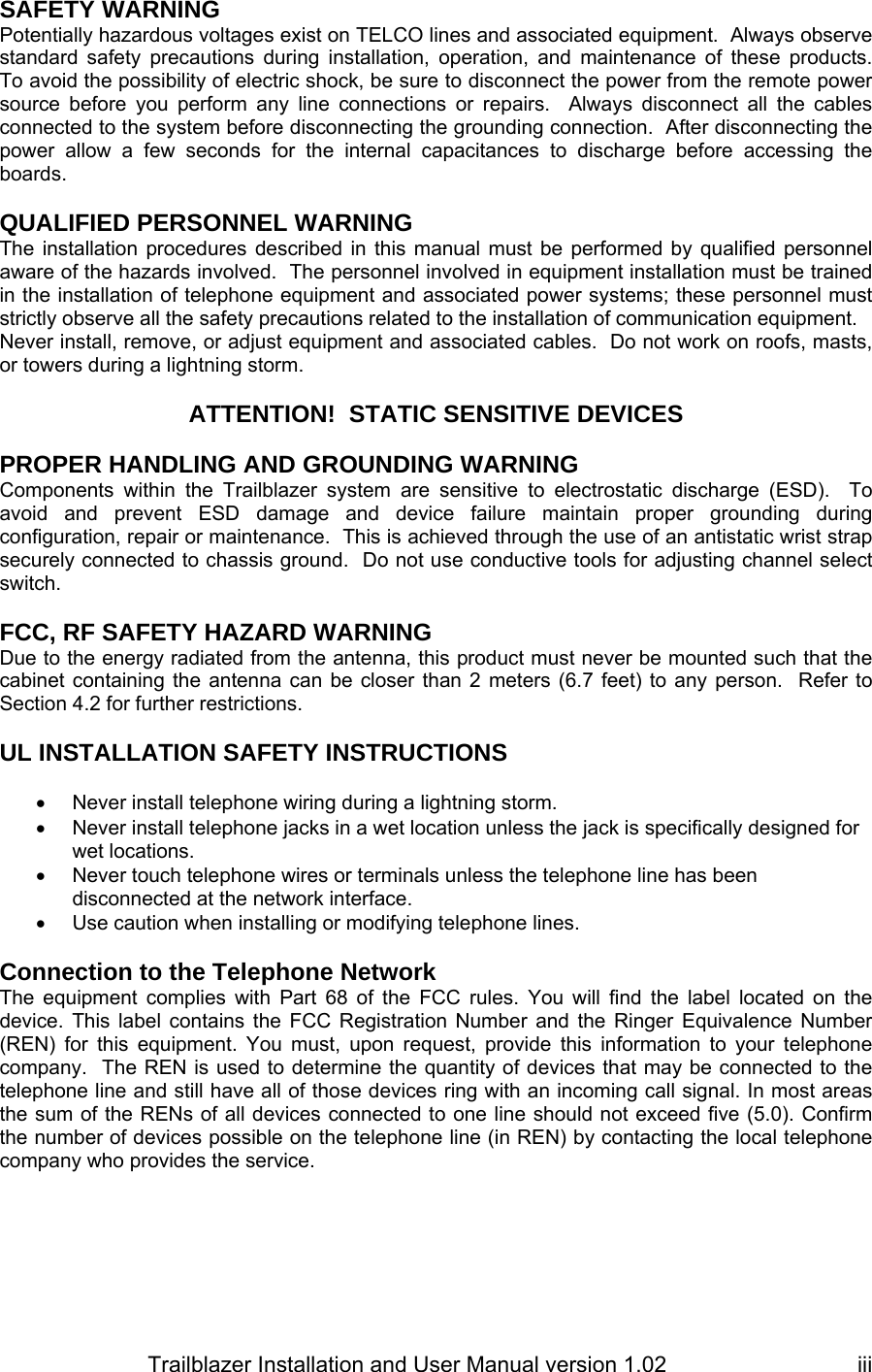

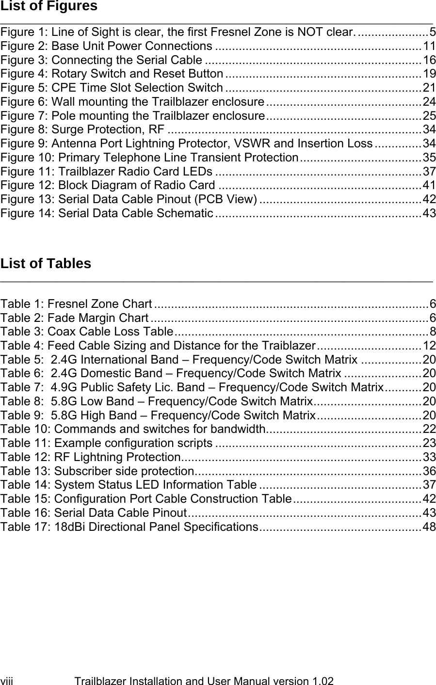

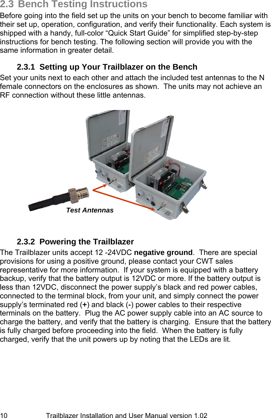
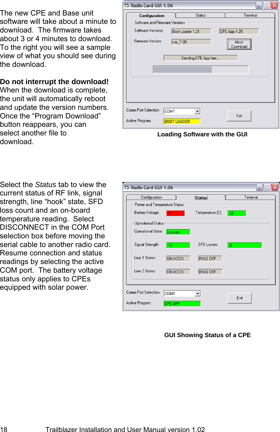
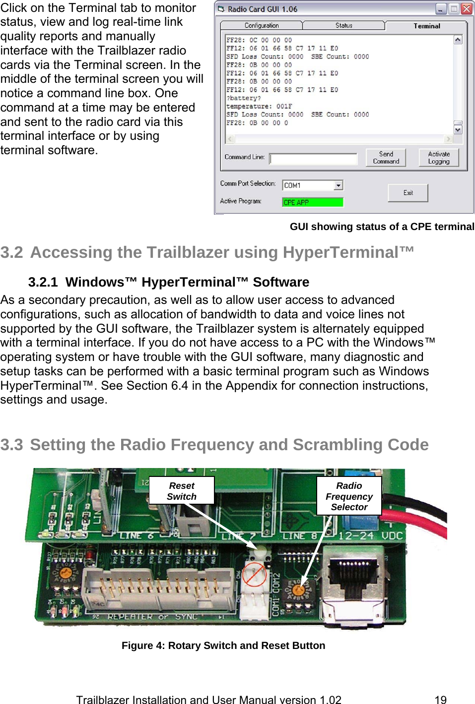
![Trailblazer Installation and User Manual version 1.02 16 3 Operation 3.1 Configuring and Accessing the Trailblazer Unit 3.1.1 Connecting the Serial Cable You can access your Trailblazer with the GUI program, included on the CWT product CD, and the included serial cable. Simply plug the DB 9 connector of the serial cable into the serial port on your computer and the three pin connector to the three pin connector (COM1) on the radio board (bottom board) as shown. DO NOT USE COM2! It is currently reserved for future applications. NOTE: Unpredictable results may occur if you are using a USB to serial COM Port adapter! Should you need to replace the serial cable, contact CWT or see Section 6.3.1 in the appendix for a pin-out and a description on how to make one. Figure 3: Connecting the Serial Cable 3.1.2 Installing the CWT GUI on Your PC The CD included with your system contains a folder called “GUI” with the self executing file CWT Trailblazer GUI 1.0x.xxxx [ALL-OS].exe. Browse to the CD and open the file to install the GUI program on your PC. After you have successfully installed the GUI, start the program by either double clicking the CWT Trailblazer GUI ver. x.xx file on your desktop or browse start-> programs-> Carlson Wireless Technologies Inc-> CWT Trailblazer GUI ver. x.xx 3.1.3 Using the GUI Double click the CWT icon and choose the appropriate COM port connected to your serial cable. RESET CONNECT SERIAL CABLE TO COM1 HERE (Don’t use COM2!)](https://usermanual.wiki/Carlson-Wireless-Technologies/TB49/User-Guide-619601-Page-24.png)
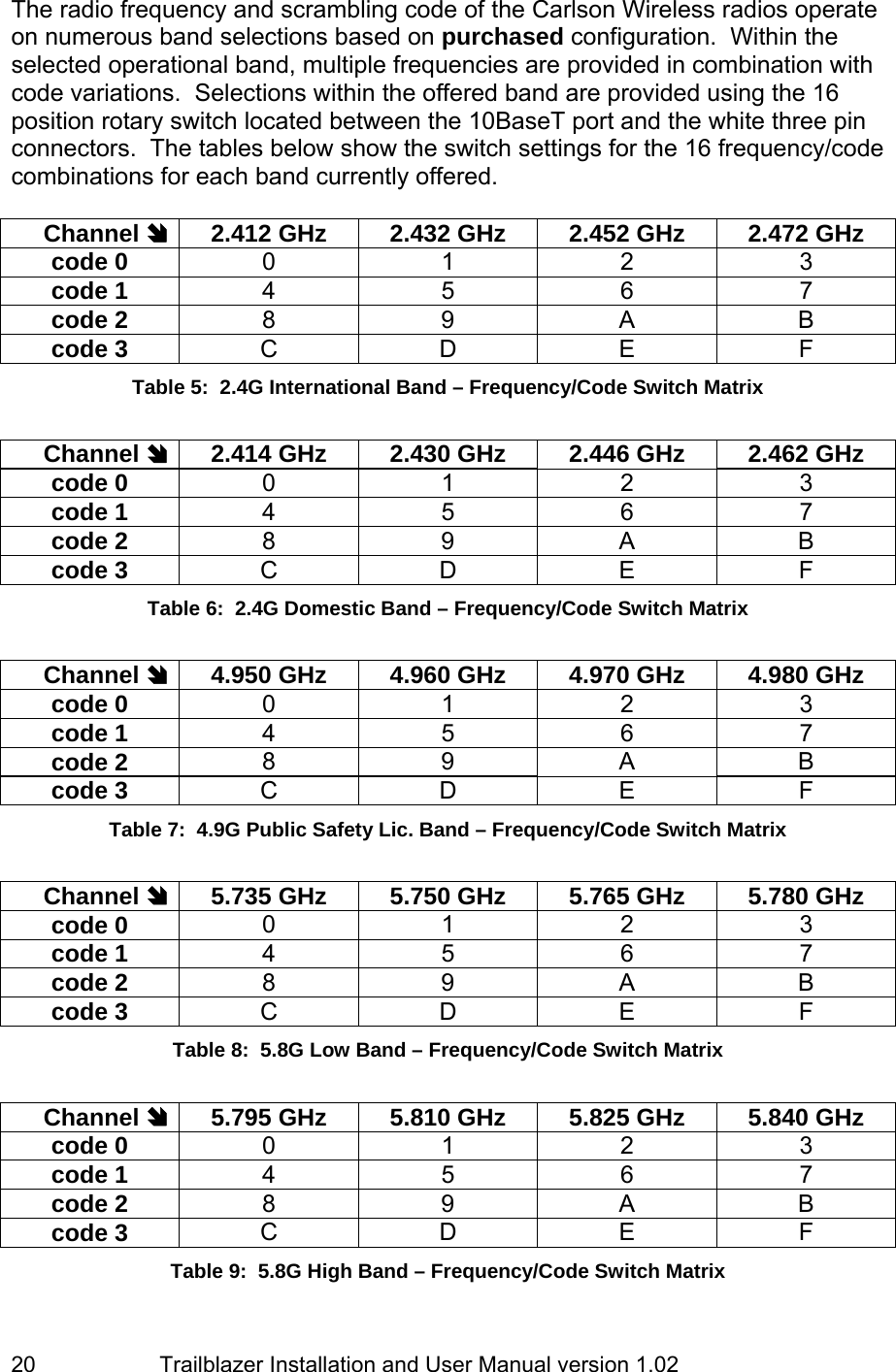
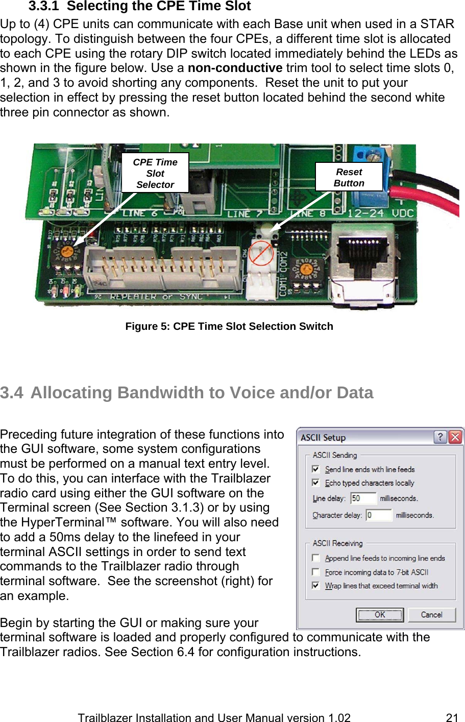
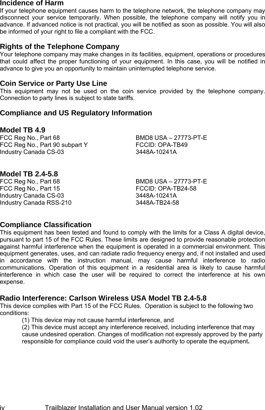
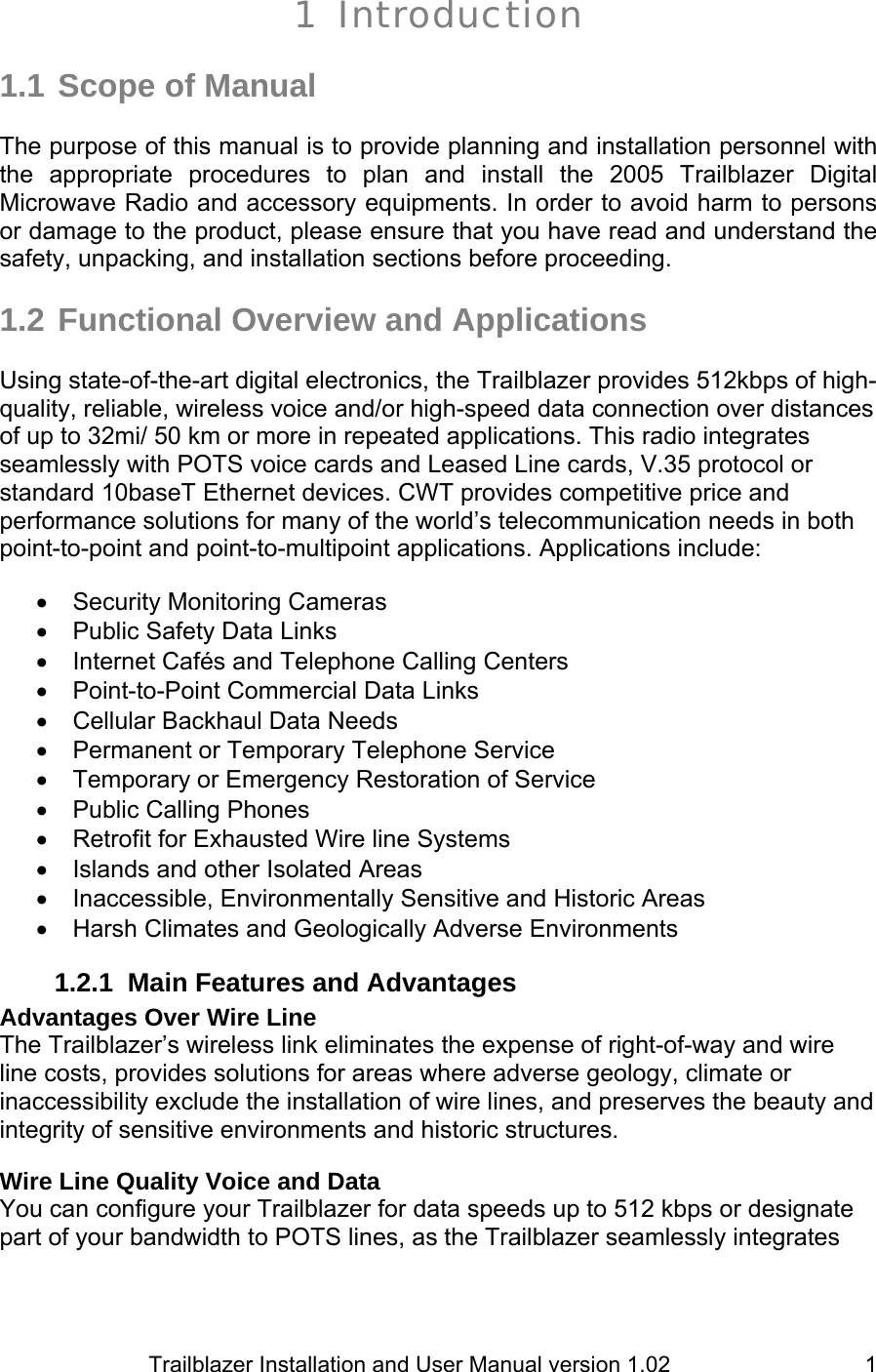
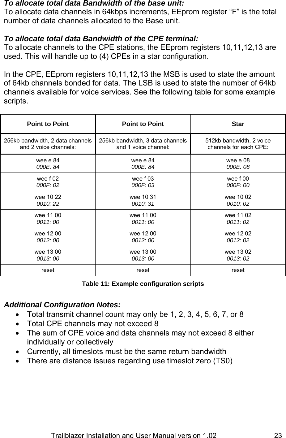
![Trailblazer Installation and User Manual version 1.02 22 Each setting is controlled by a short “command name” followed by an EEprom register or “switch” designated by a letter or letters on your screen. Type the command name for the function you wish to implement followed by the appropriate “switch” and press enter. The Trailblazer radio card should respond by echoing the new setting back to you. It usually takes (7) sets of these commands to configure a radio card for any of its many functional states. The settings may be changed one at a time or combined in a text file, known as a “script”, and loaded into the Trailblazer radio card. See the following table for details and examples. Write to EEprom register EEprom register 0=Star 8=P2P# of Total Ch. wee e Write to EEprom register EEprom register # of Data Channels wee f 0 Write to EEprom register EEprom register # of Data Ch. # of Voice Ch. CPE 0 wee 10 CPE 1 wee 11 CPE 2 wee 12 CPE 3 wee 13 reset Table 10: Commands and switches for bandwidth To set for Star topology or Point-to-Point and Bandwidth of the Base unit: This is set using the EEprom register “E”. If the first digit of the switch setting or “most significant digit” is an “8” then it is planned to be in point-to-point mode. If the first is “0” or none then it will be in Star mode. The second digit or “least significant digit” is for the bandwidth (as transmitted from the base unit) with the number corresponding to how many 64 kb channels are made available. For example, type in though Hyper terminal or the GUI window [wee e 84] The system should respond back with [000E: 84] This will set up a Point to Point with 256 kb available bandwidth. Entering [wee e 08] would set the radio to be a Star with 512 kb bandwidth.](https://usermanual.wiki/Carlson-Wireless-Technologies/TB49/User-Guide-619601-Page-30.png)


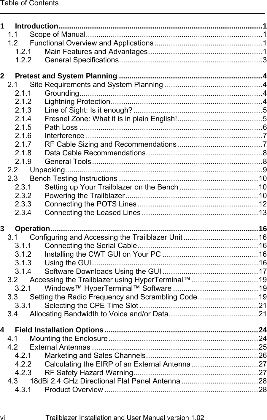
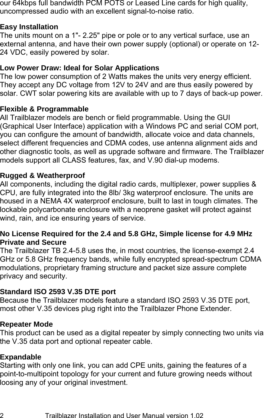
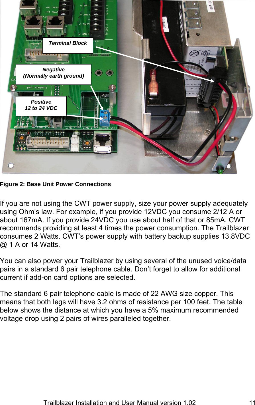
![Trailblazer Installation and User Manual version 1.02 45 6.4.2 Setting the V35 enable and port location To enable the V35 data port, open up the Hyperterminal™ interface and if you are communicating with a CPE unit after booting type: [stop]. If you are connected to a base unit it will stop on it’s own after a minute. Then type in: [wee 5 1] or [wee 5 2] depending on which line no you wish to be used as a data path for the Ethernet connection. The system should respond back with: 0005: 02 as shown above. To disable theV35 data port, open up the HyperTerminal™ interface and type in: [wee 5 FF] . The system should respond back with: 0005: FF . 6.4.3 Received Signal Strength Indicator (RSSI) The RSSI value can be accessed through the Command Line Interface using the following command: rdm ff28 4 <enter>. The figure at right shows the output for the RSSI from the CPE unit. The RSSI value is repeated 4 times, but just look at a single number. The figure to the right shows an RSSI of 0C. The RSSI should be 8 or higher. If the value displayed contains an alphabetic character (A, B, C, D, E or F), the value is greater than 9. The undesirable RSSI values are from 00 to 07.](https://usermanual.wiki/Carlson-Wireless-Technologies/TB49/User-Guide-619601-Page-53.png)
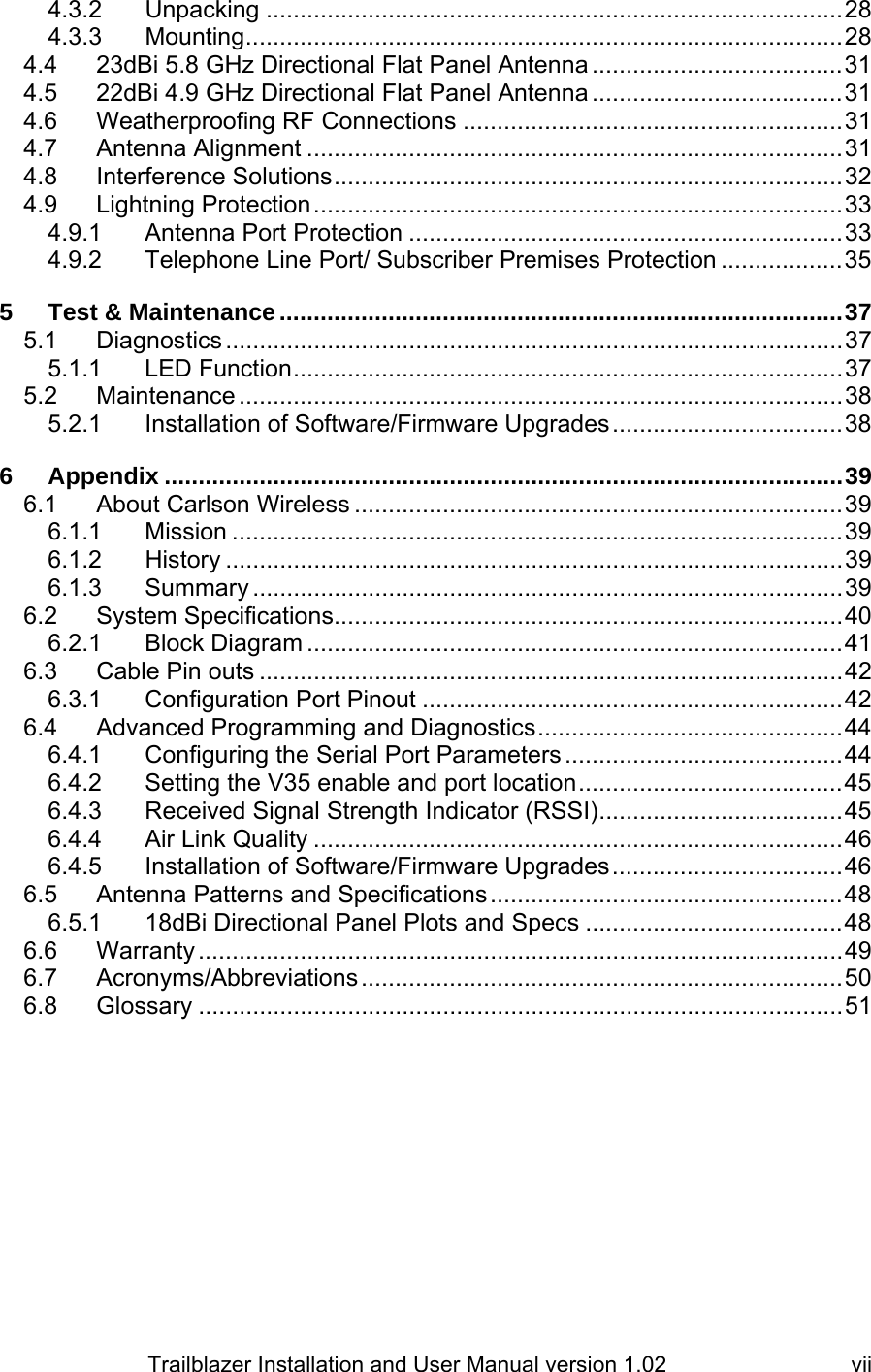
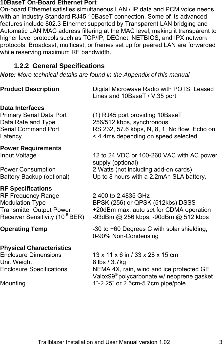
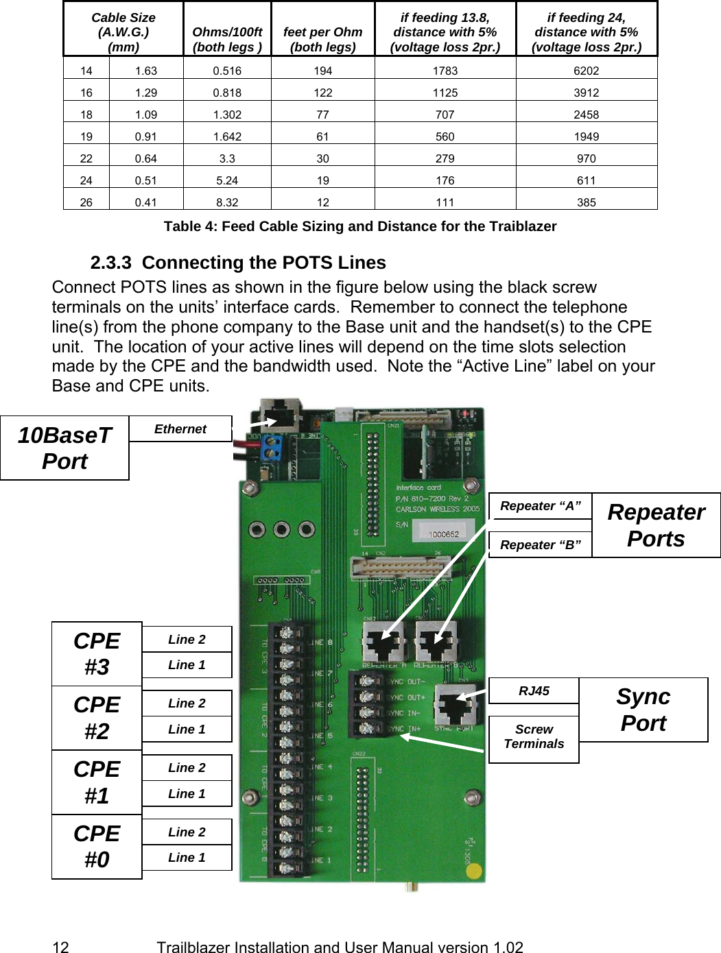
![Trailblazer Installation and User Manual version 1.02 46 The RSSI command can be used on the base unit. The above figure displays the results of the command. 3 of the 4 values will always read 00, just ignore these values. 1 of the 4 numbers should be greater than 7. If the value displayed contains an alphabetic character (A, B, C, D, E or F), the value is greater than 9. In the above example the RSSI value is sufficient. 6.4.4 Air Link Quality The quality of the Air Link can be interrogated through the Command Line Interface using the following command: debug 1 <enter>. This command causes the Air Link statistics to be printed every 4 seconds. The statistics can be stopped by typing, debug 0 <enter>. The processing of the debug command is illustrated in the following figure. With a completely clean link, the SFD Loss Count and Signal Byte Error Count should be both zero. A SFD Loss Count greater than (6) could indicate a low signal strength or external interference. 6.4.5 Installation of Software/Firmware Upgrades In addition to maintenance using the GUI software, as a failsafe the software/firmware for the Trailblazer systems can be upgraded in the field through the serial port using a terminal emulation program and the Command Line Interface. 1. Reset the board using the RESET button near the rotary channel switch. 2. Stop the program through the Command Line Interface. The figure above illustrates this step. When the Boot program starts, the software version information is displayed. When the prompt “Boot Loader Ready” appears, type: [stop] and press: <enter>. The Boot program confirms the stop command by displaying the text “Boot Loader Stopped”. If the text “Boot Loader Stopped” is not displayed immediately, RESET the unit and try again. Although timing is not extremely critical, try to type the command in the first couple of seconds.](https://usermanual.wiki/Carlson-Wireless-Technologies/TB49/User-Guide-619601-Page-54.png)