Cambium Networks 50450I Wireless Ethernet Bridge, Dual Channel OFDM MIMO Combination Access Point, Subscriber Station and Point to Point Equipment User Manual PMP PTP 450i Series User Guide
Cambium Networks Limited Wireless Ethernet Bridge, Dual Channel OFDM MIMO Combination Access Point, Subscriber Station and Point to Point Equipment PMP PTP 450i Series User Guide
Contents
- 1. Installation Guide
- 2. User Guide Part 1
- 3. User Guide Part 2
- 4. User Guide Part 3
- 5. User Guide Part 4
- 6. User Guide Part 5
- 7. User Guide Part 6
- 8. User Guide Part 7
- 9. Exhibit D Users Manual per 2 1033 b3
- 10. User Manual - Part 1
- 11. User Manual - Part 2
- 12. User Manual - Part 3
- 13. User Manual - Part 4
- 14. Users Manual - Part 5
- 15. Users Manual - Part 6
- 16. User Manual
User Guide Part 4
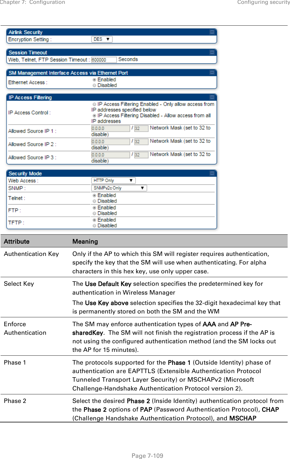
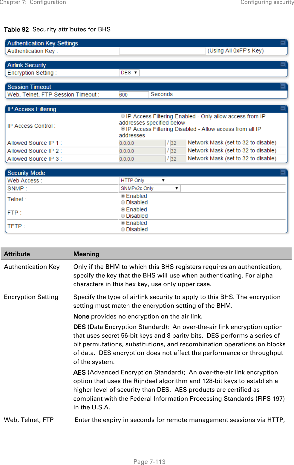
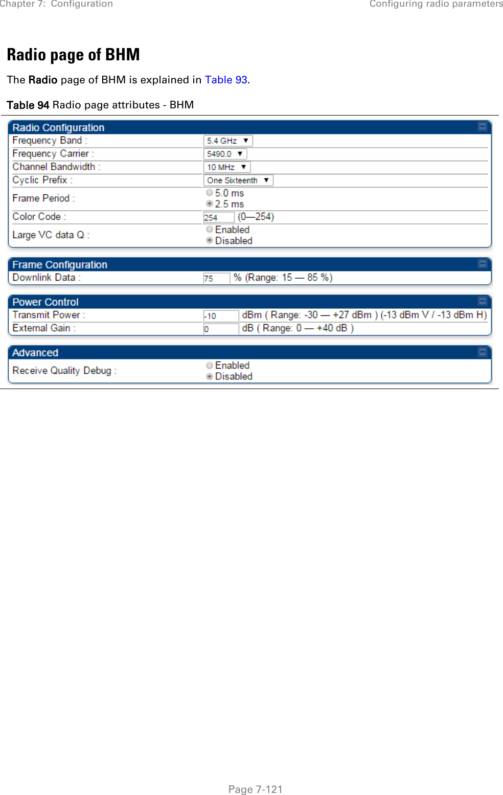
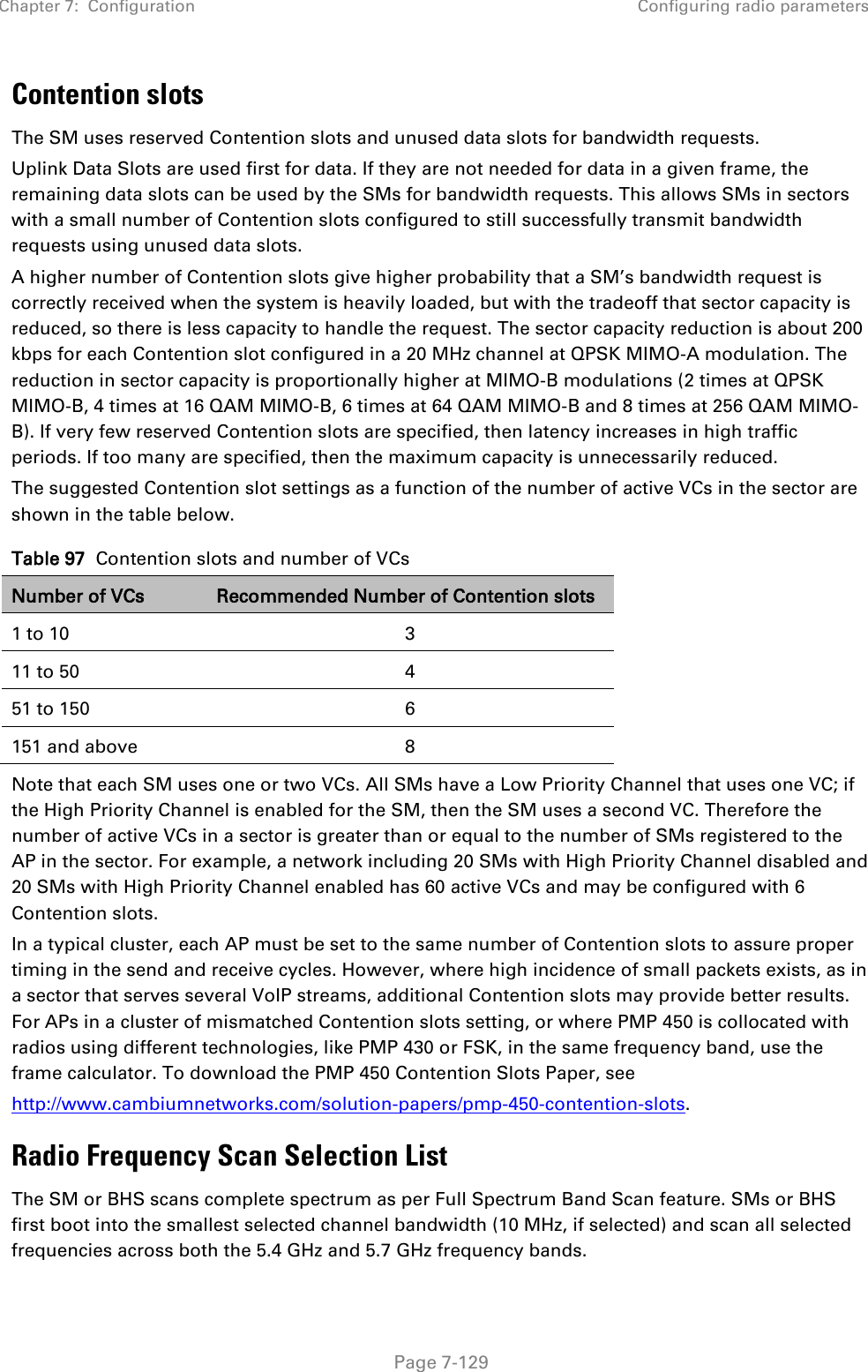
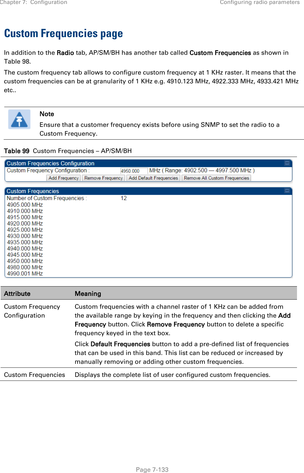
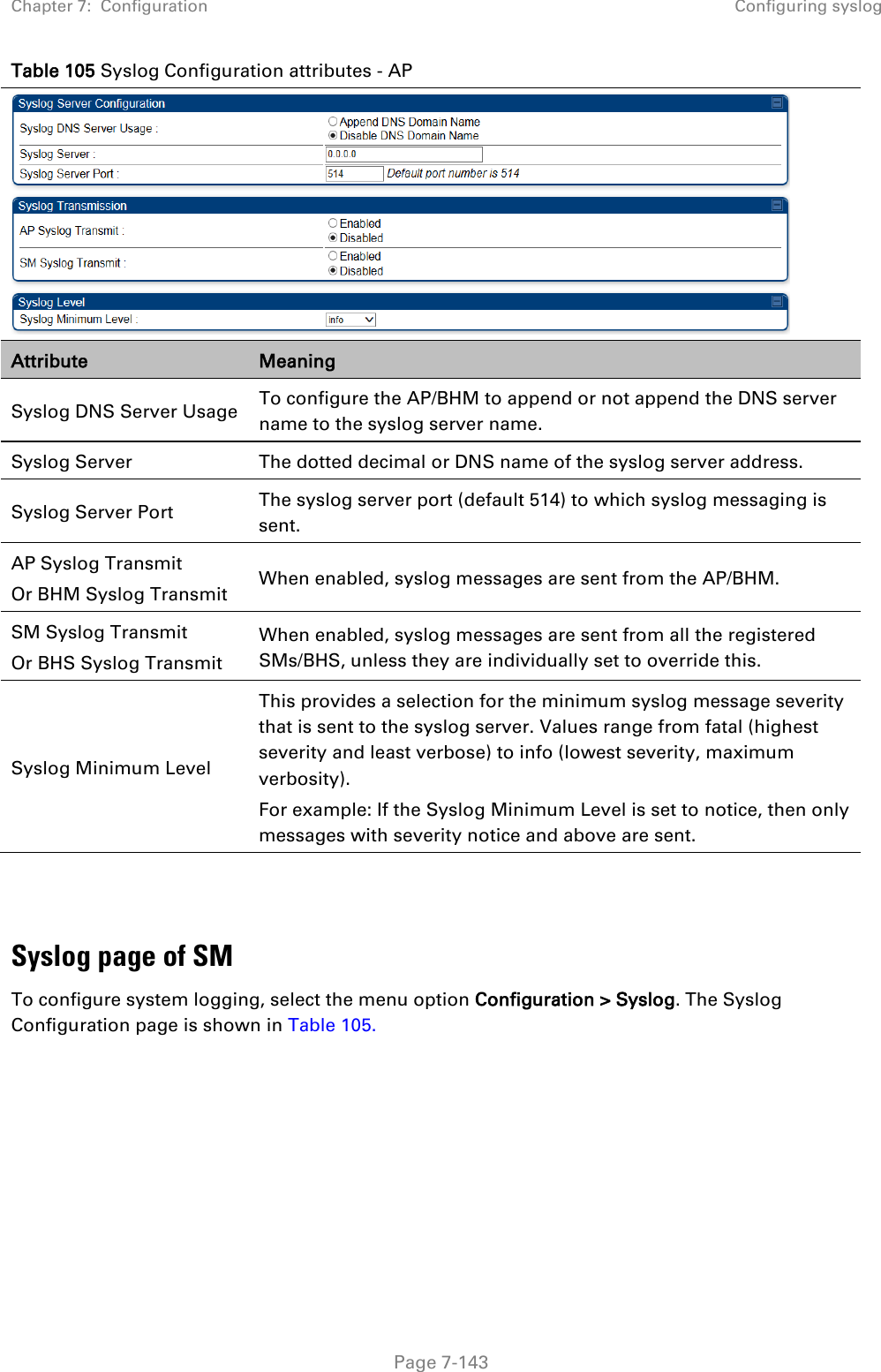
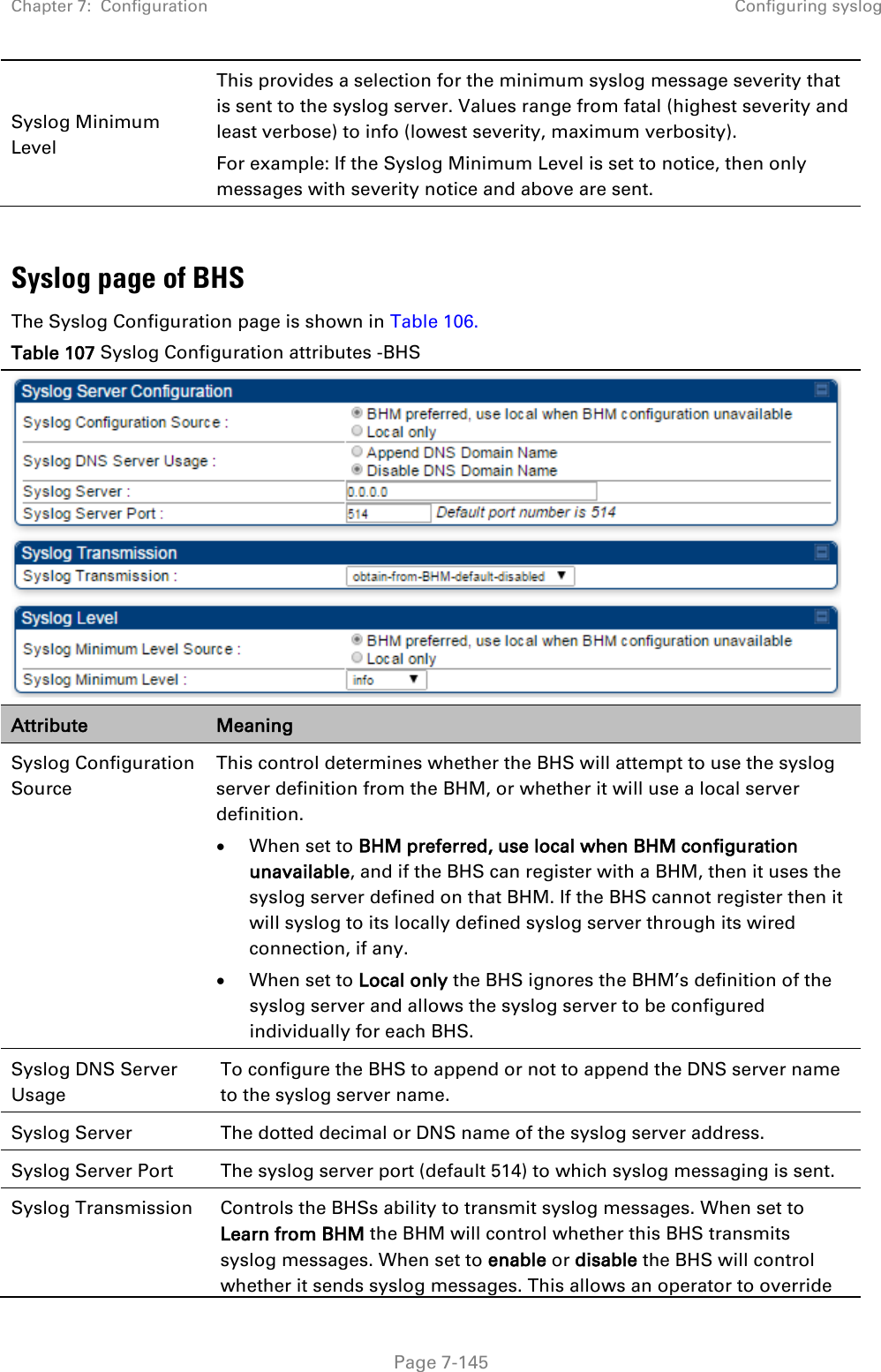
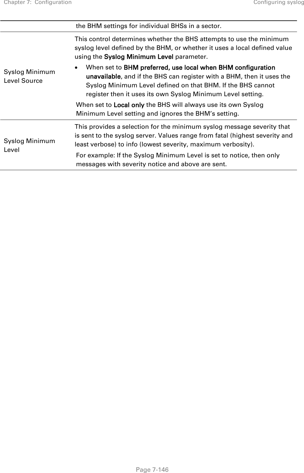
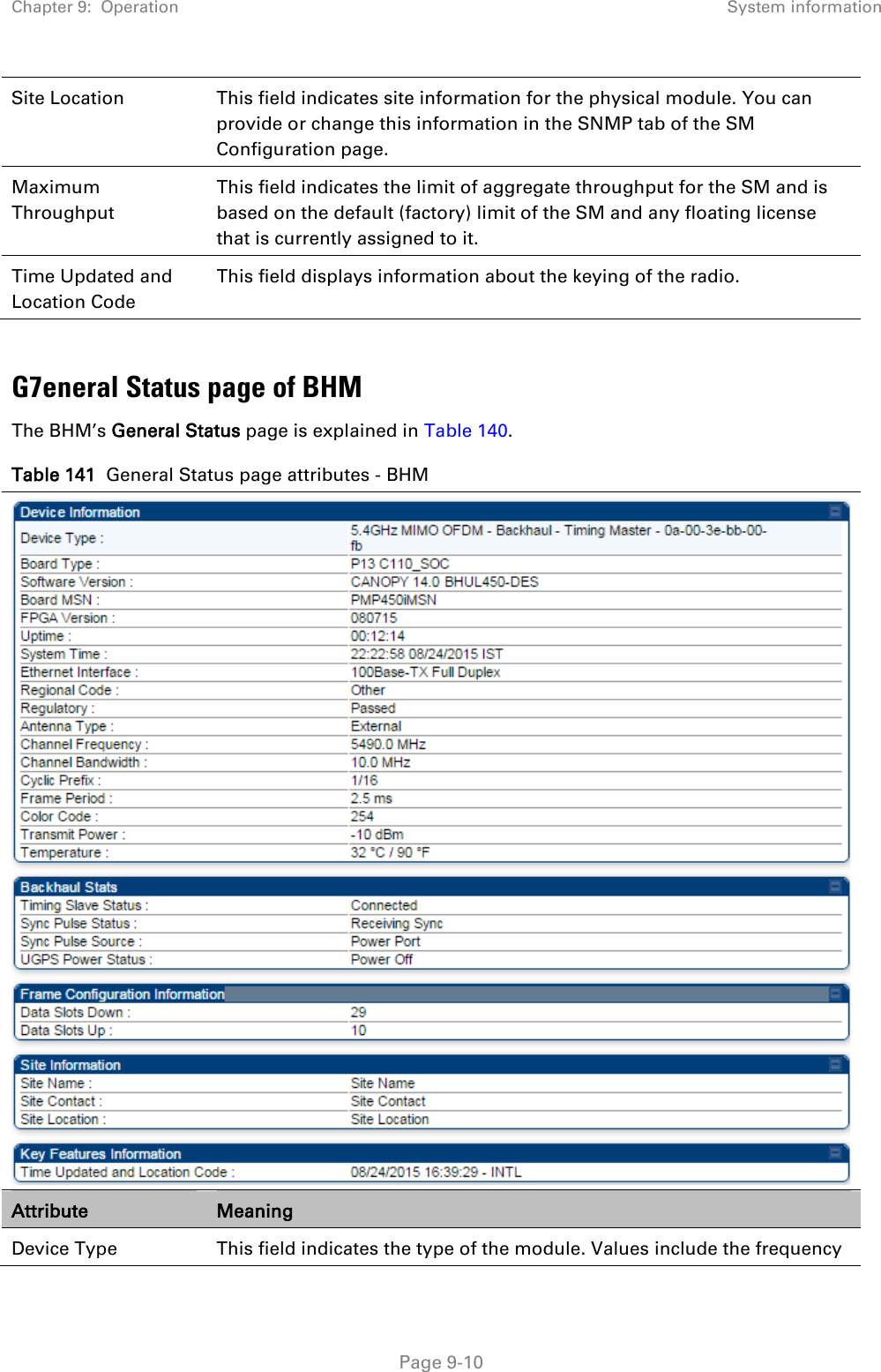
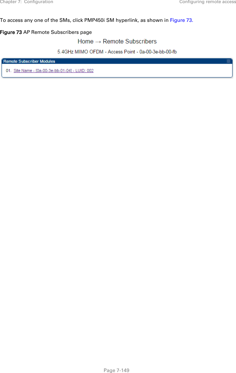
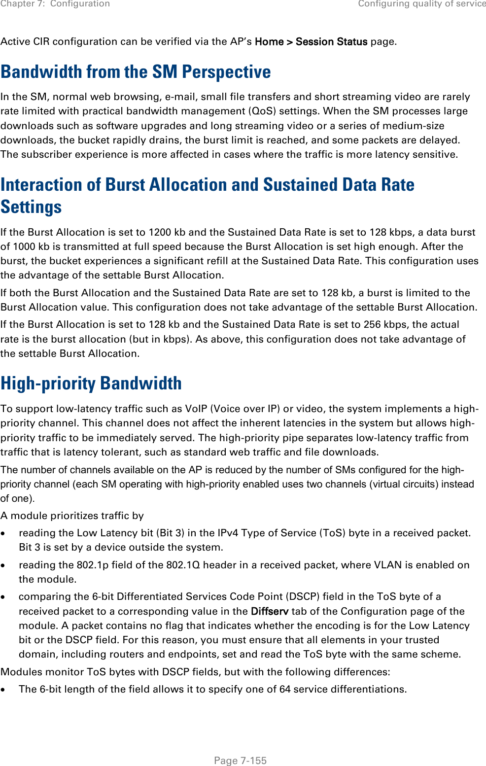
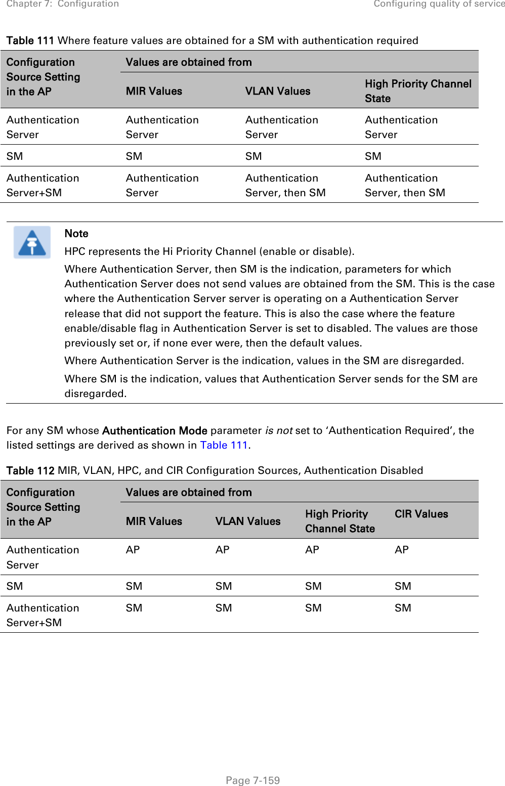
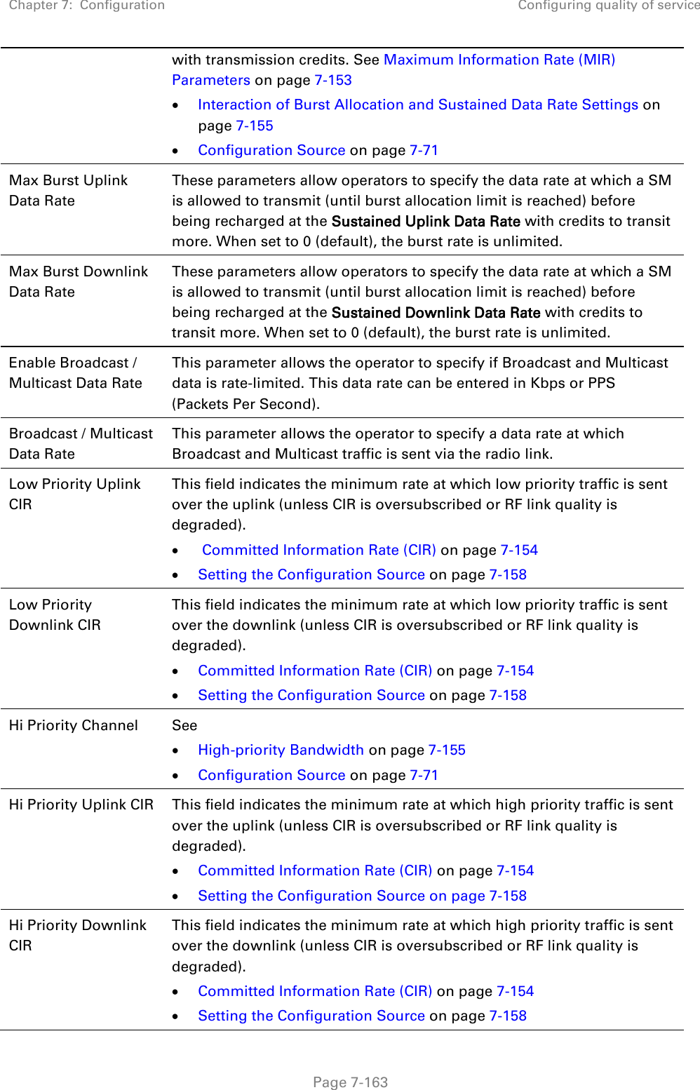
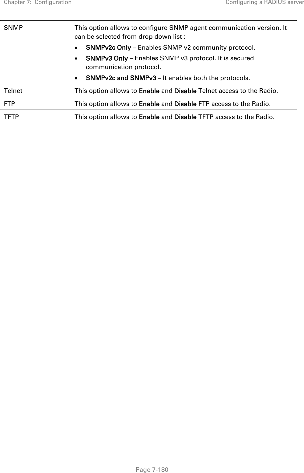
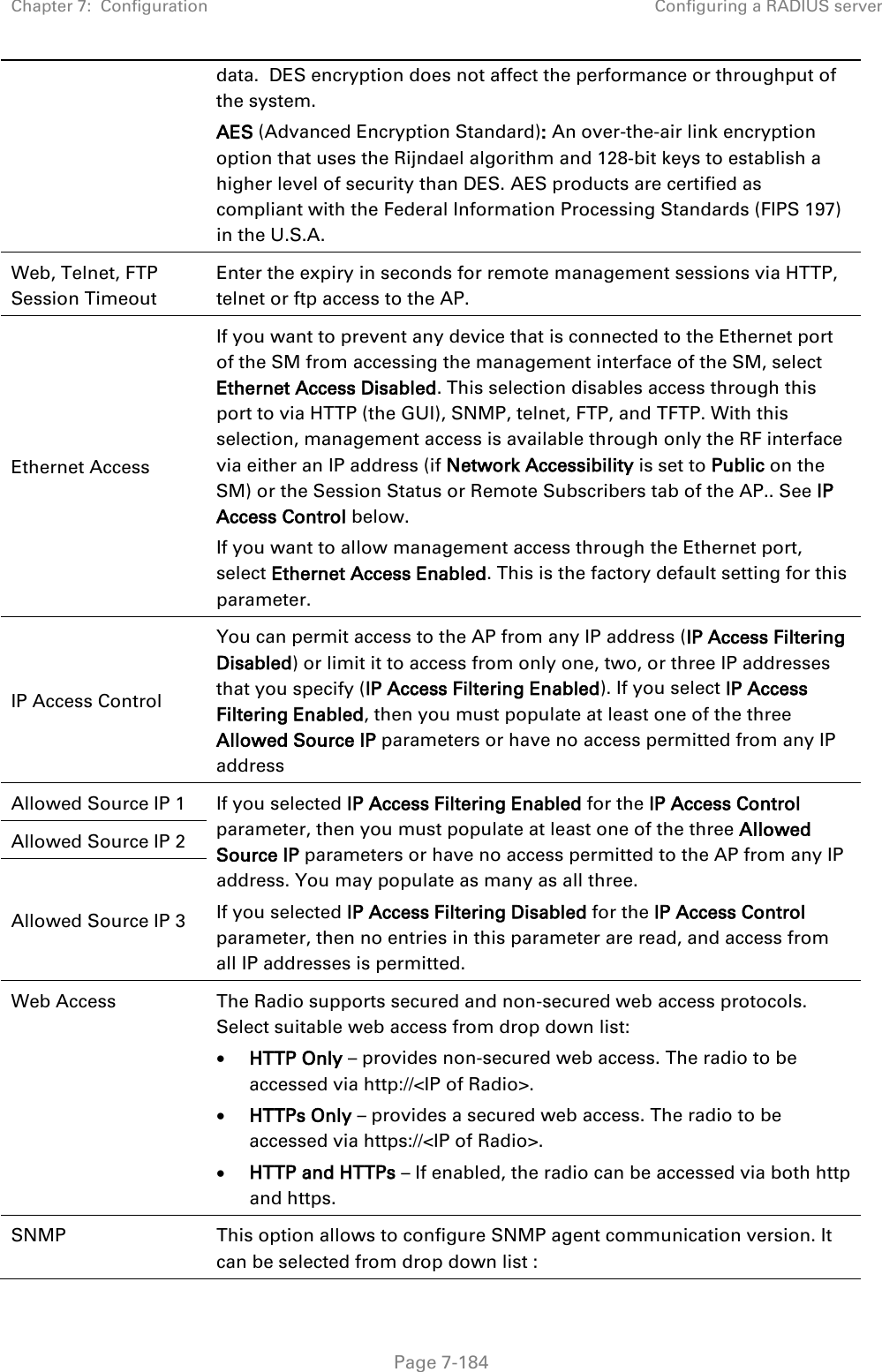
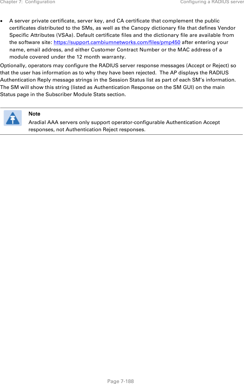
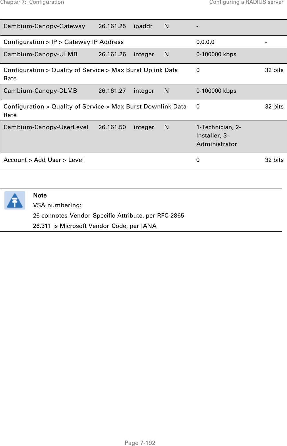
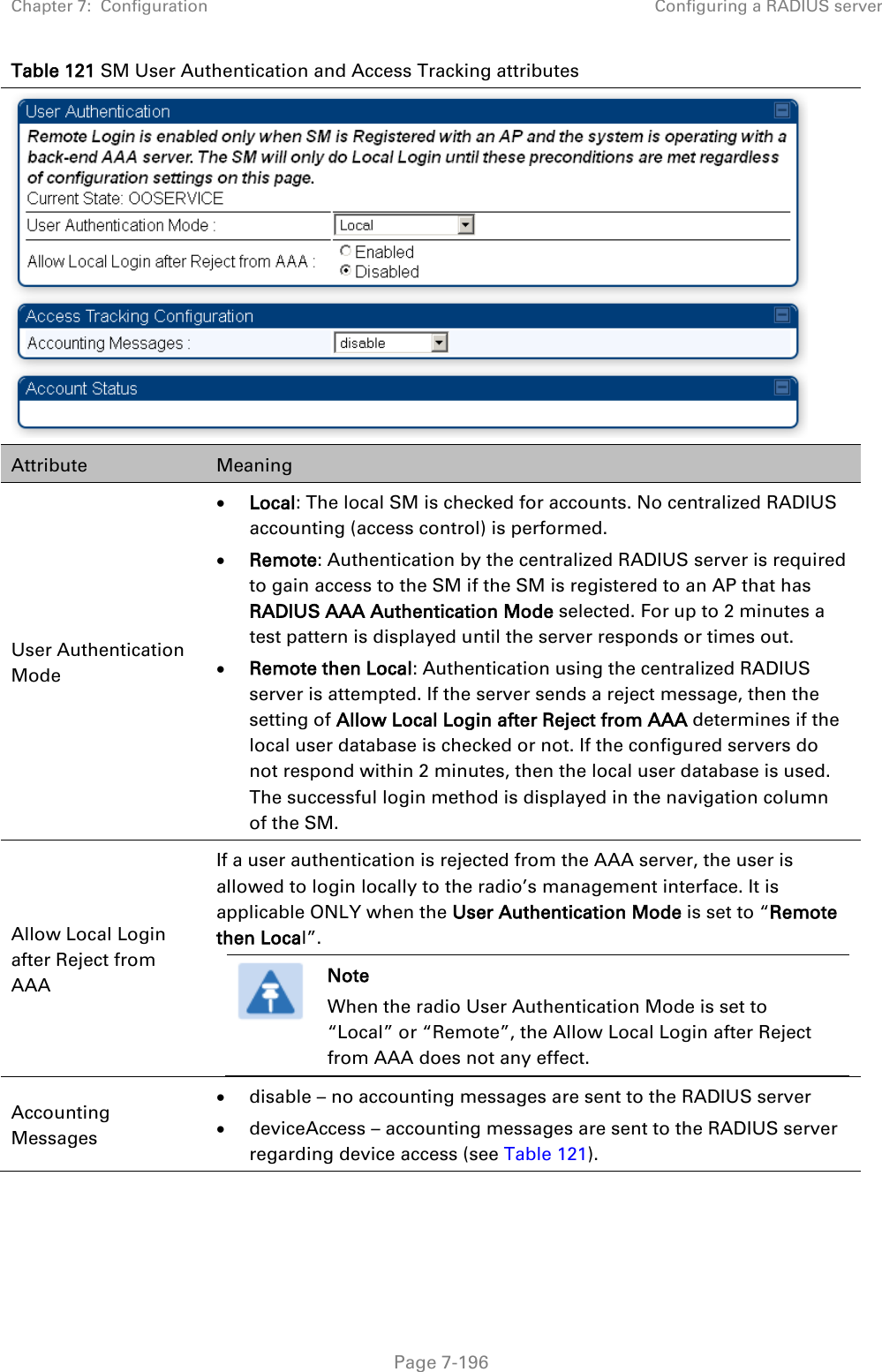
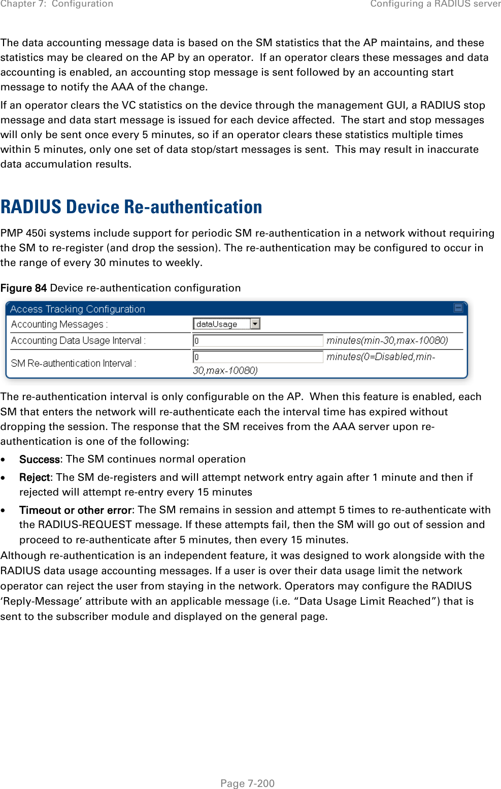
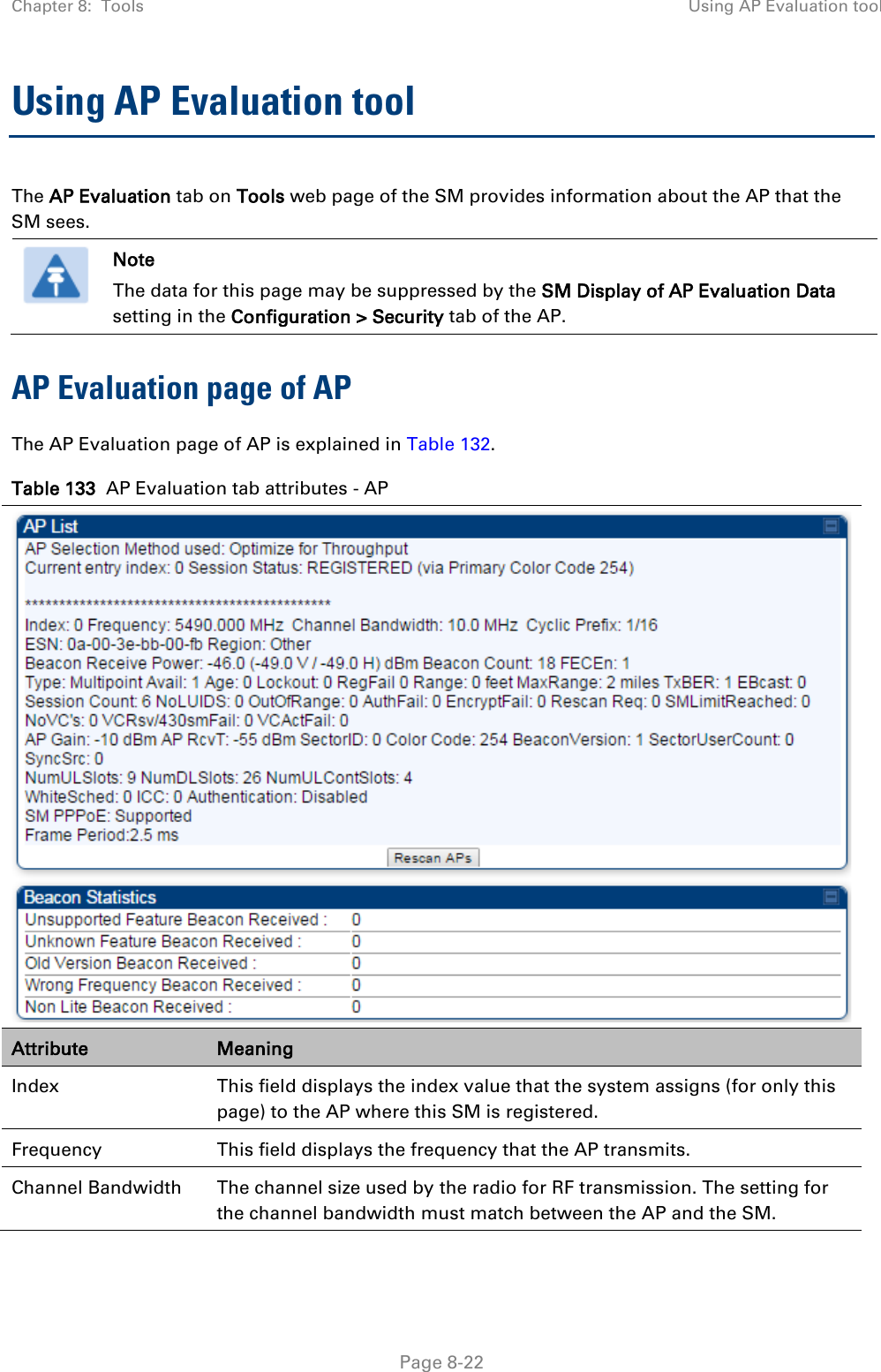
![Chapter 7: Configuration Configuring remote access Page 7-148 Preferred DNS Server The first address used for DNS resolution. Alternate DNS Server If the Preferred DNS server cannot be reached, the Alternate DNS Server is used. Domain Name The operator’s management domain name may be configured for DNS. The domain name configuration can be used for configuration of the servers in the operator’s network. The default domain name is example.com, and is only used if configured as such. Accessing SM/BHS over-the-air by Web Proxy The SM/BHS may be accessed via the AP/BHM management GUI by navigating to Home > Session Status (or Home > Remote Subscribers for AP only) and clicking on the SM’s hyperlink. For example, to access one of the SMs, click LUID: 002 – [0a-00-3e-37-b9-fd], as shown in Figure 72. Figure 72 AP Session Status page The SessionStatus.xml hyper link allows user to export all displayed SM data in Session Status table into an xml file.](https://usermanual.wiki/Cambium-Networks/50450I.User-Guide-Part-4/User-Guide-2762119-Page-42.png)

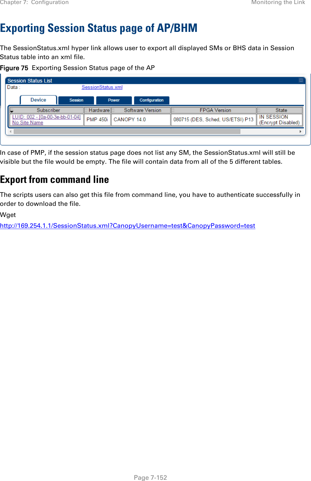
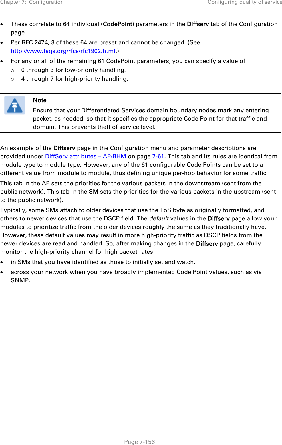
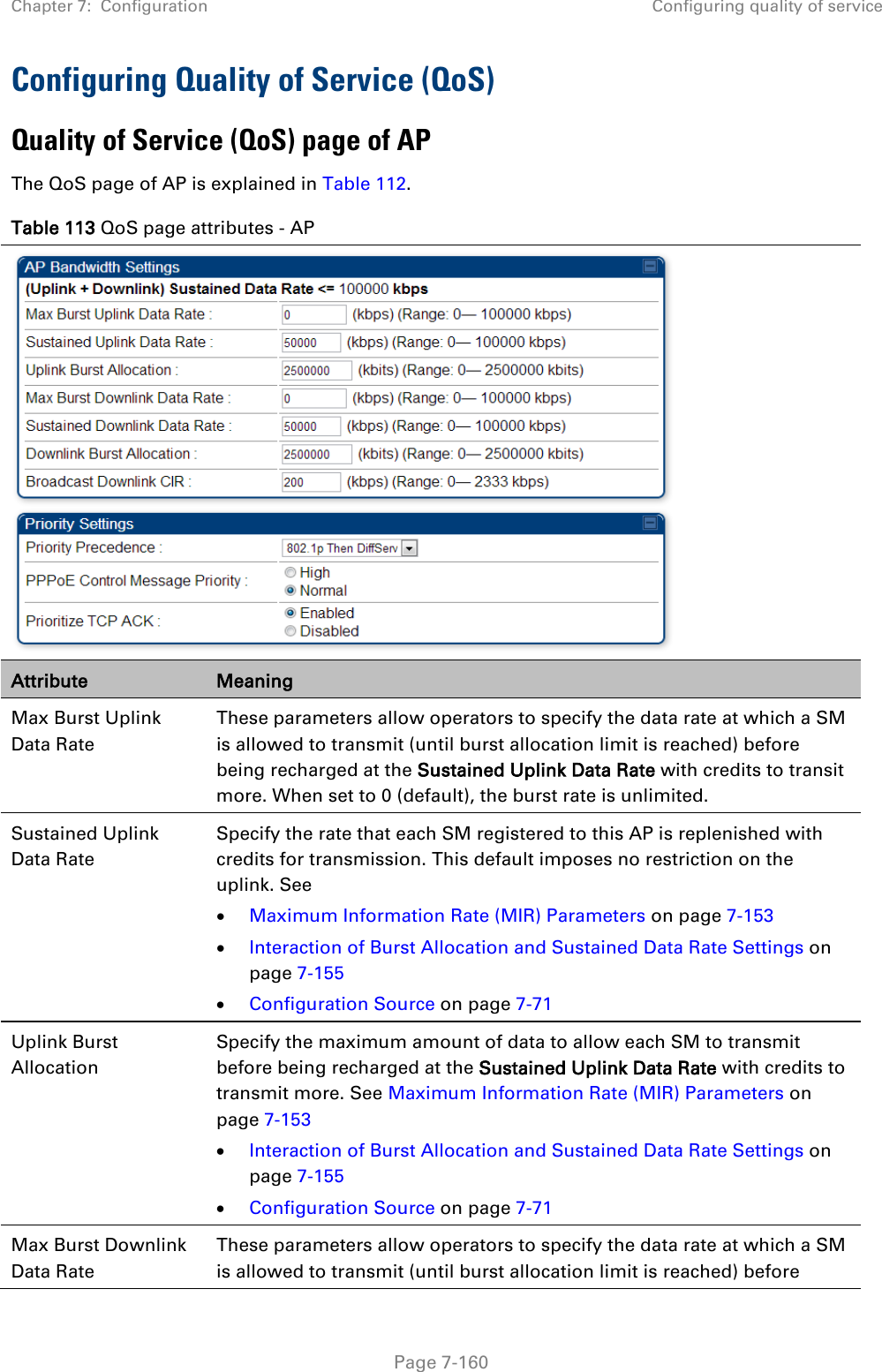
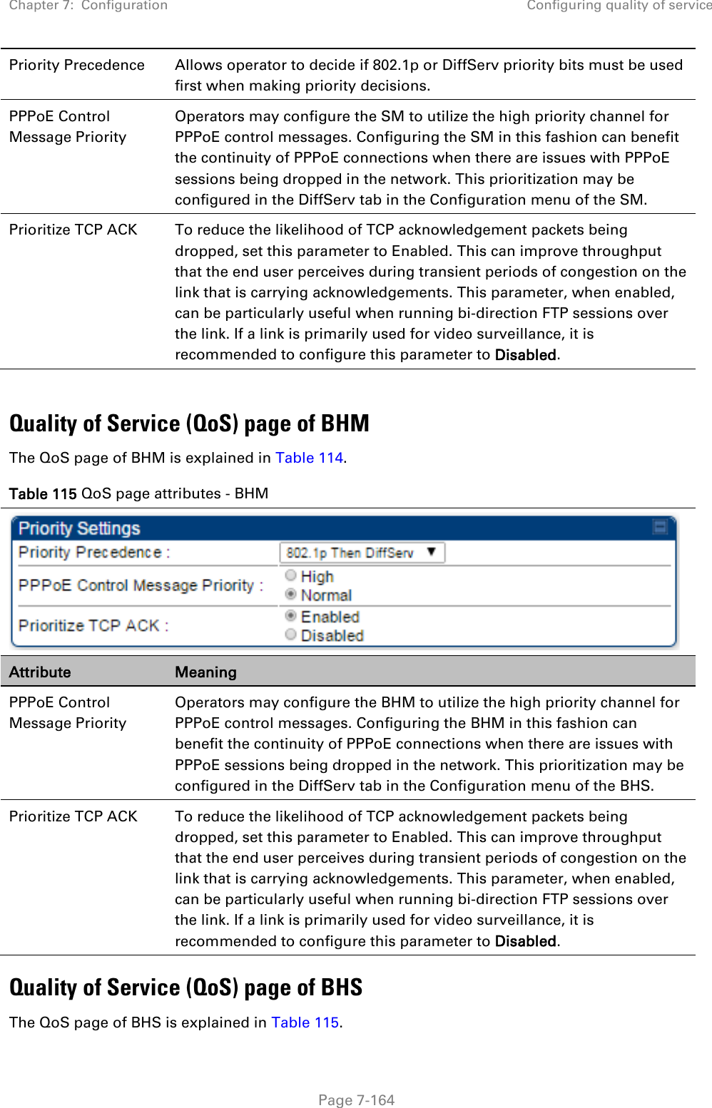
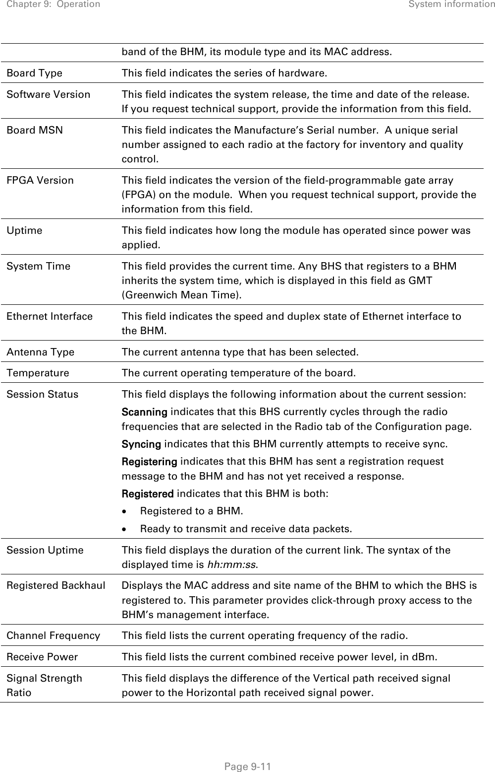
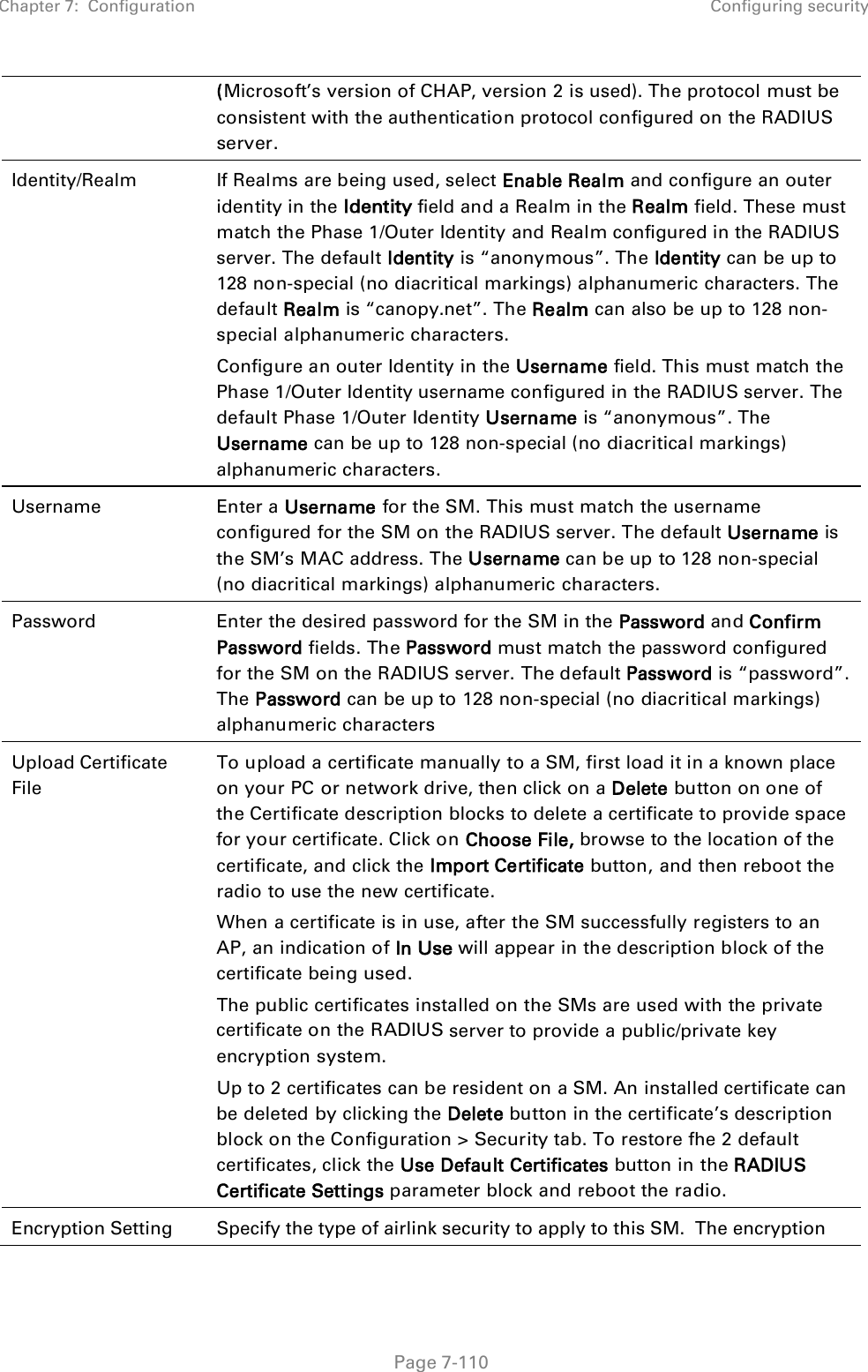
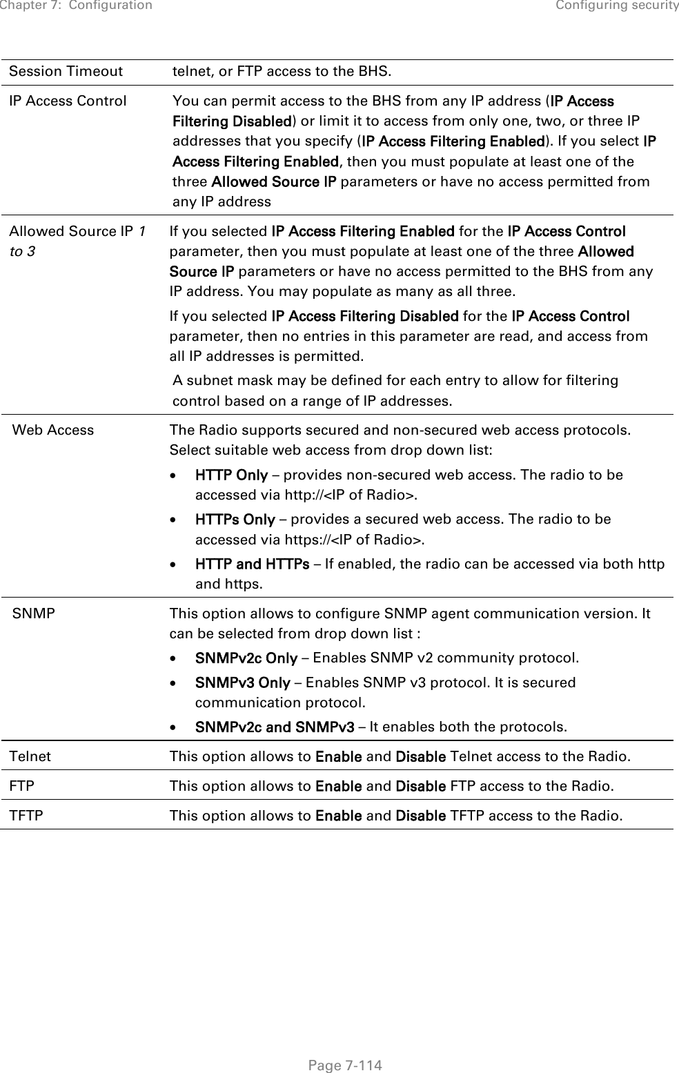
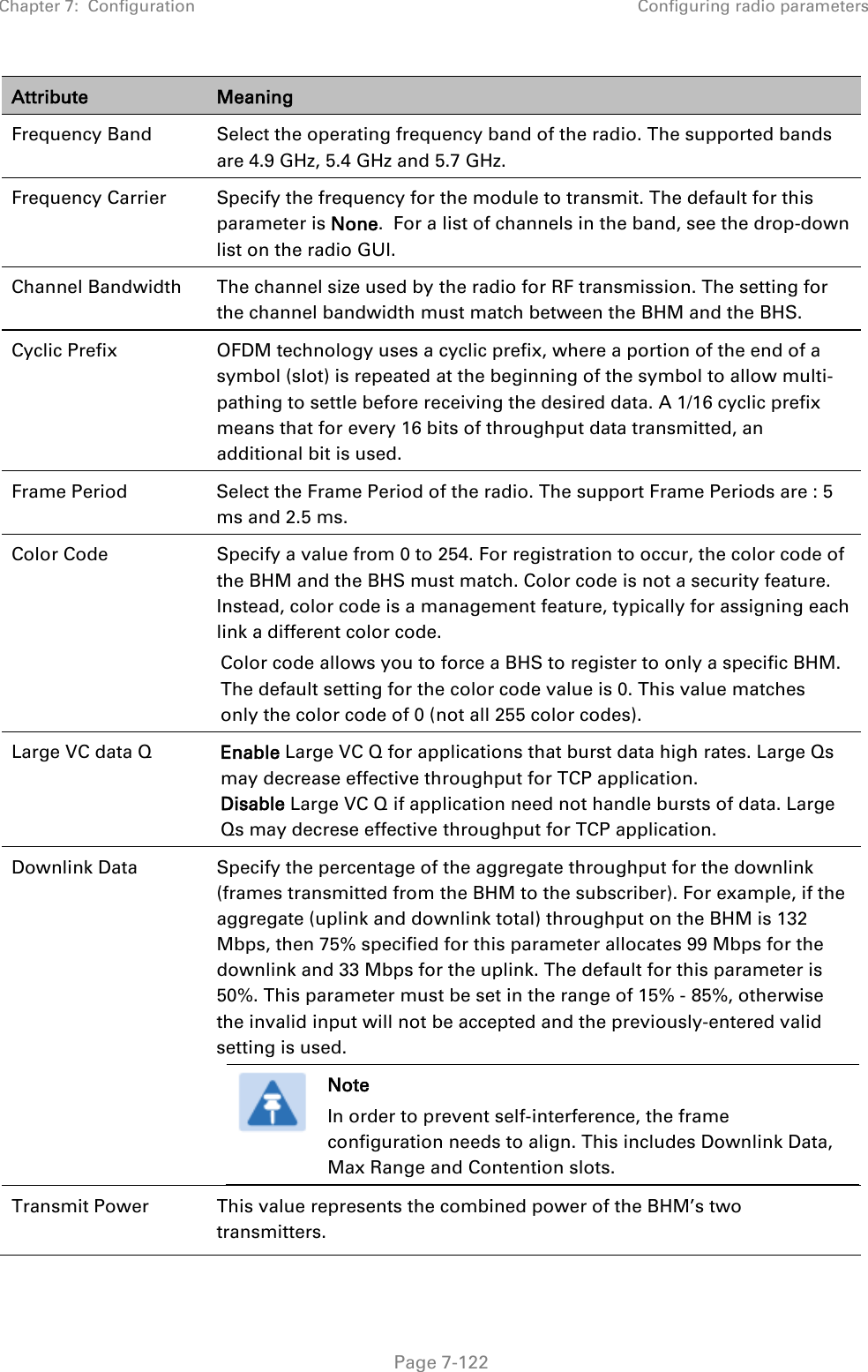
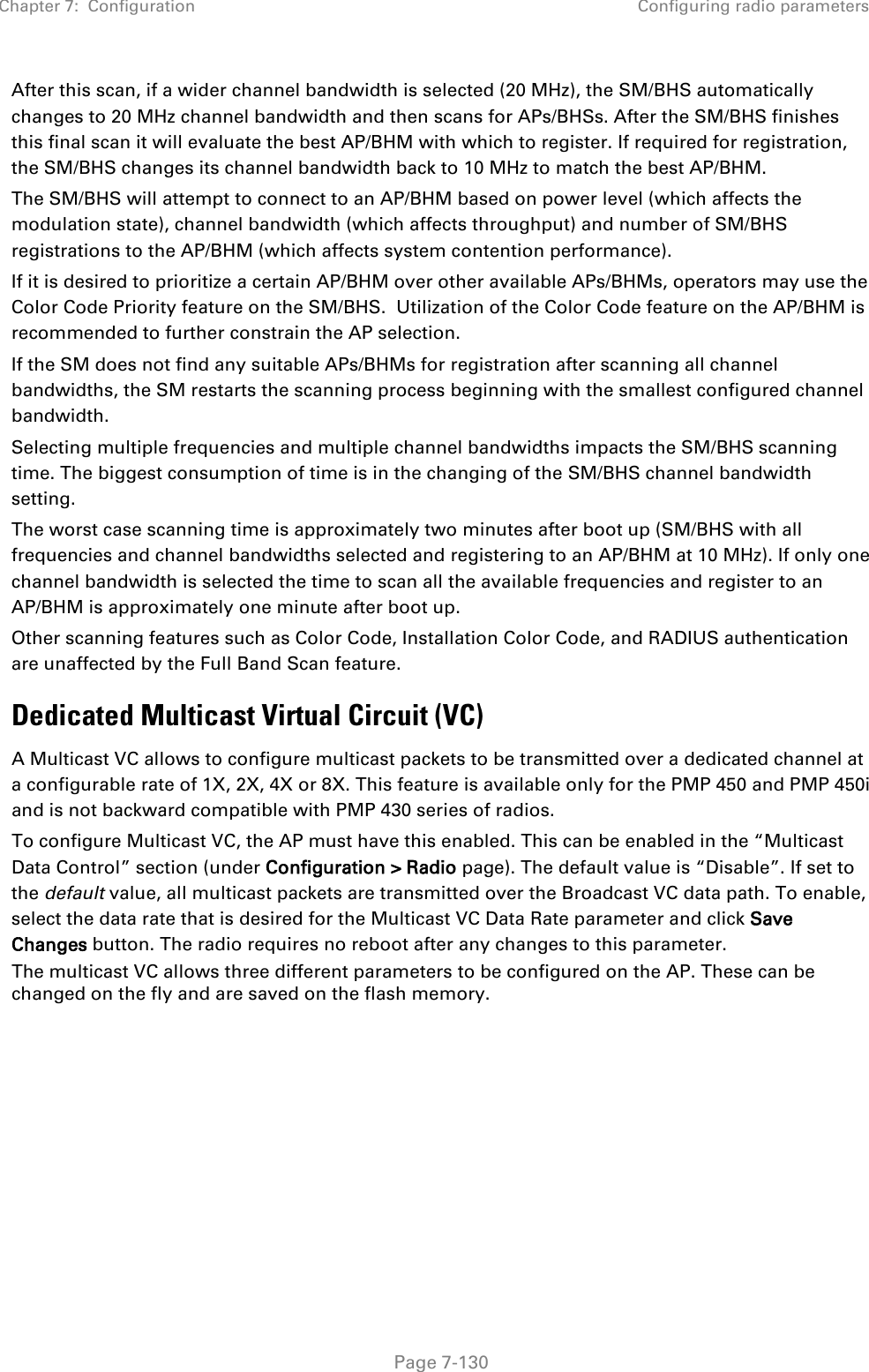
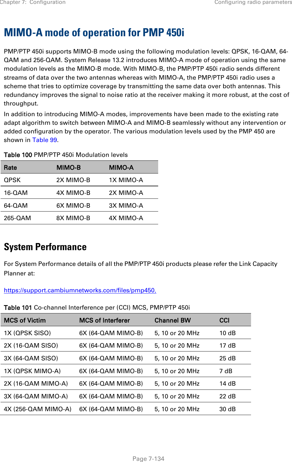
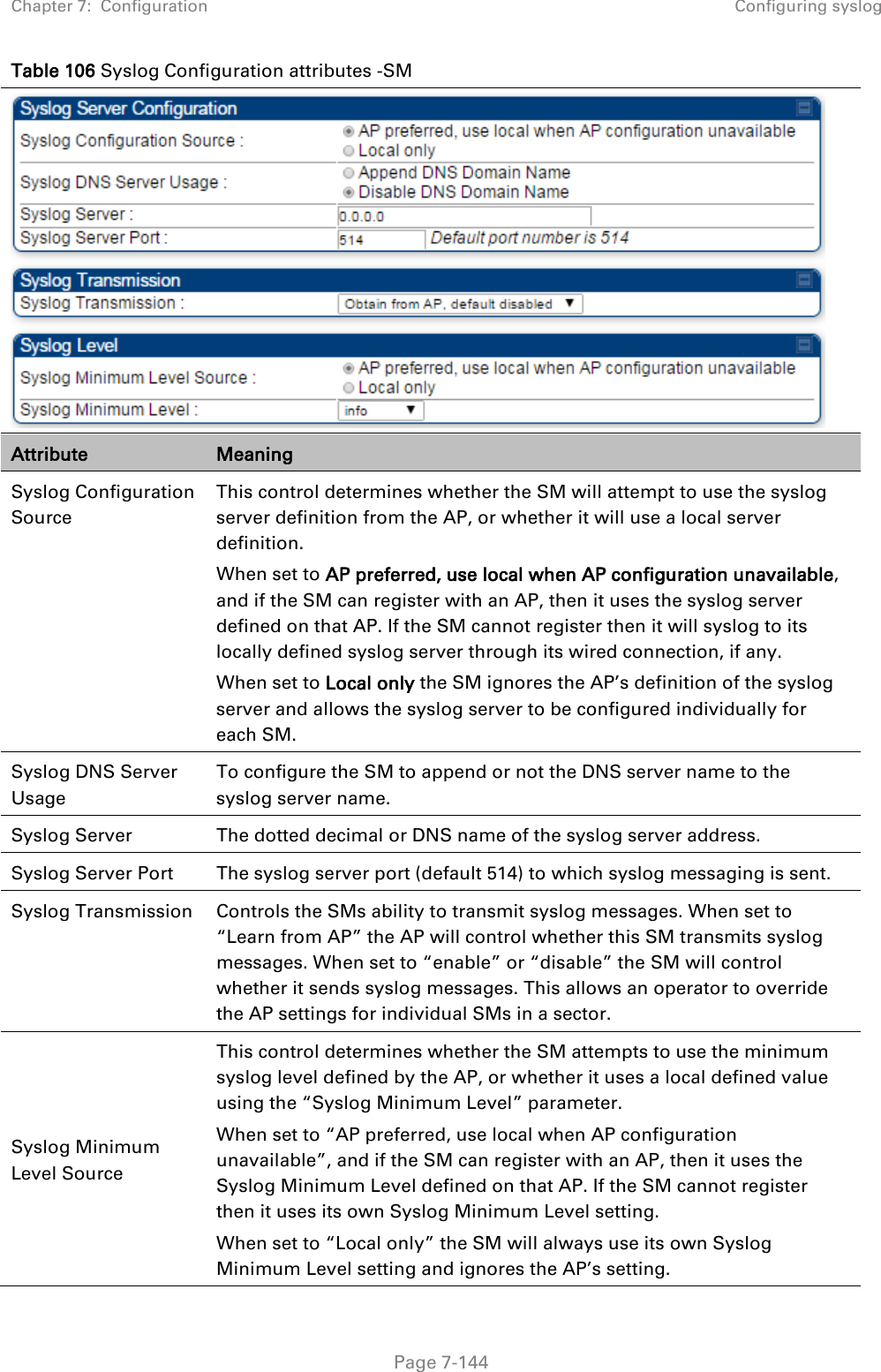
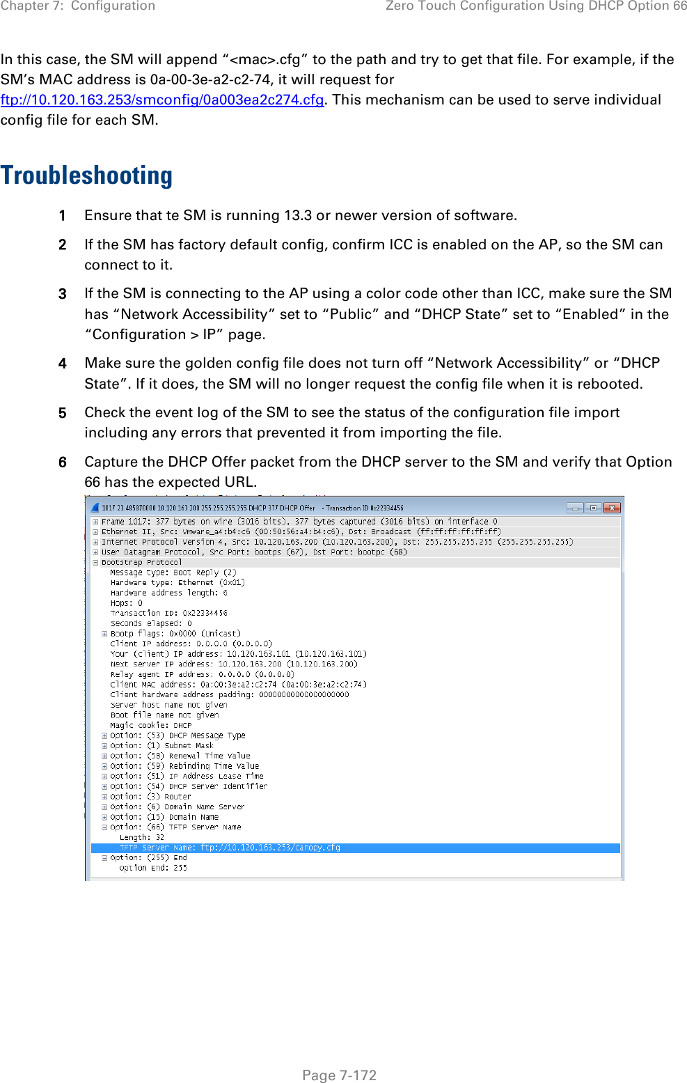
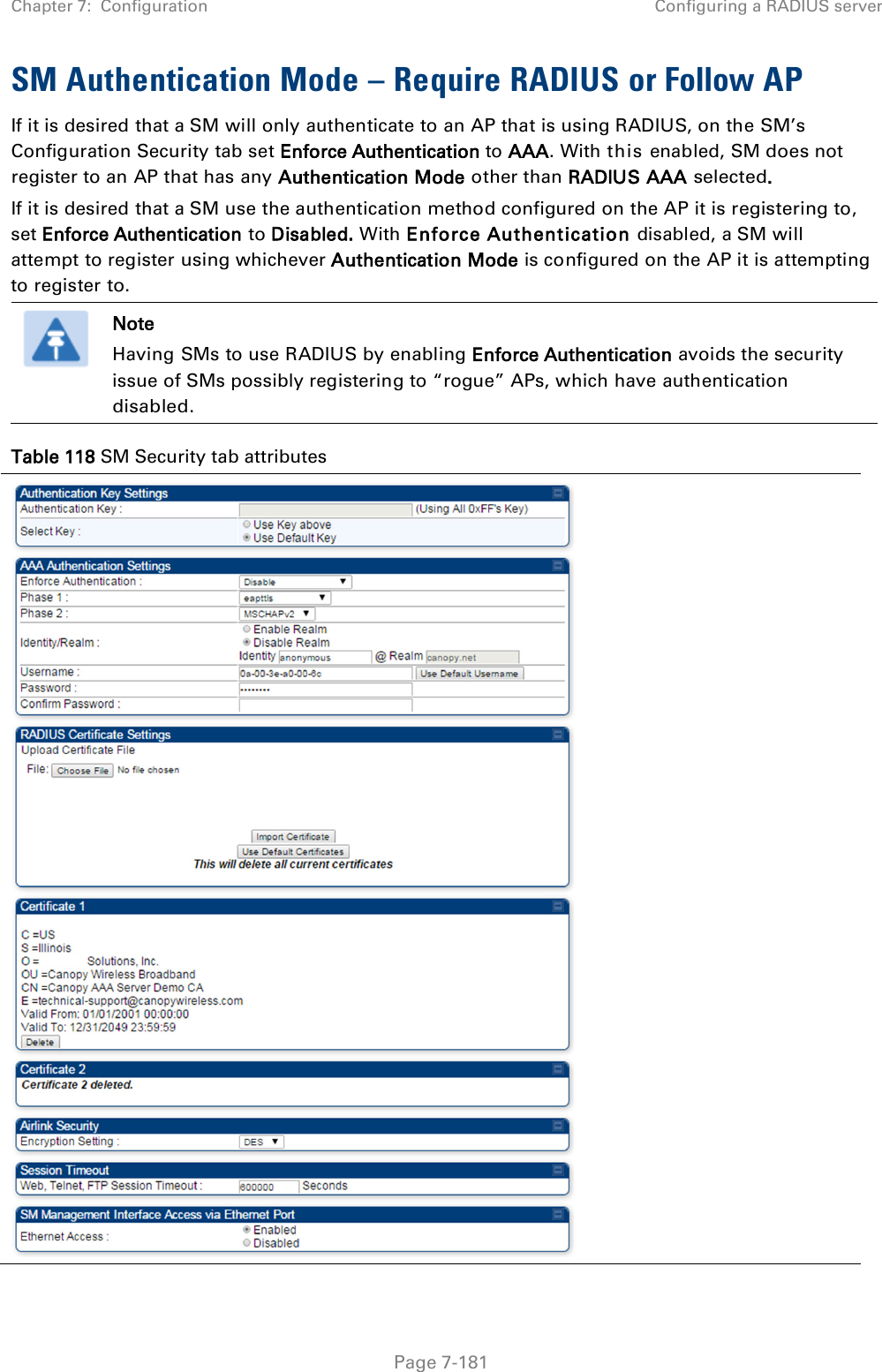
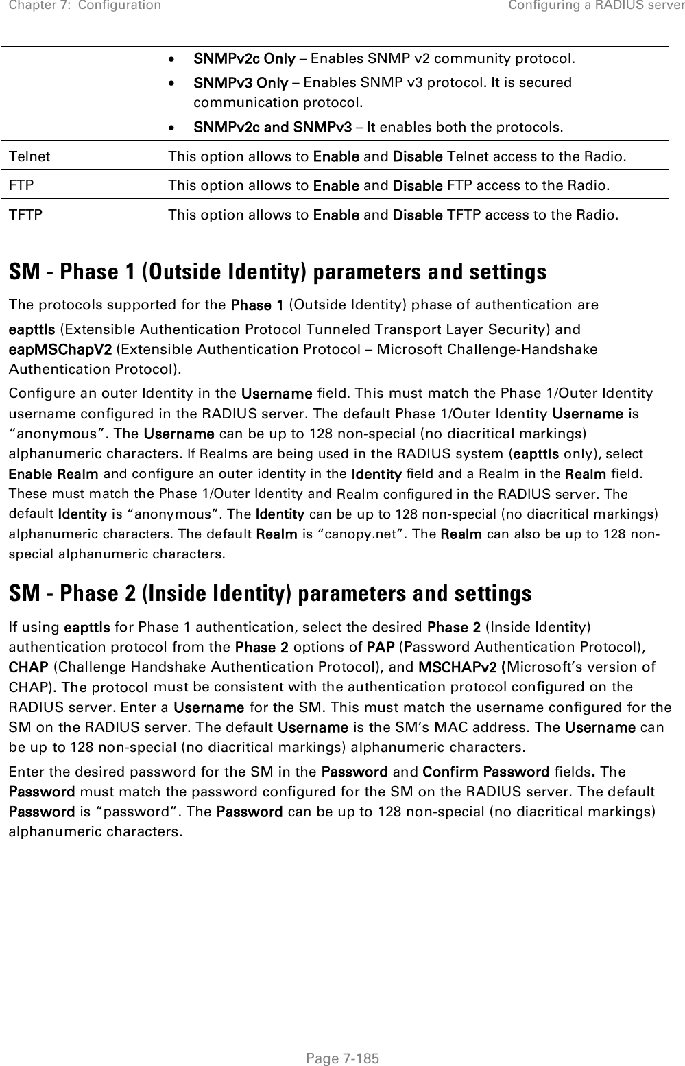
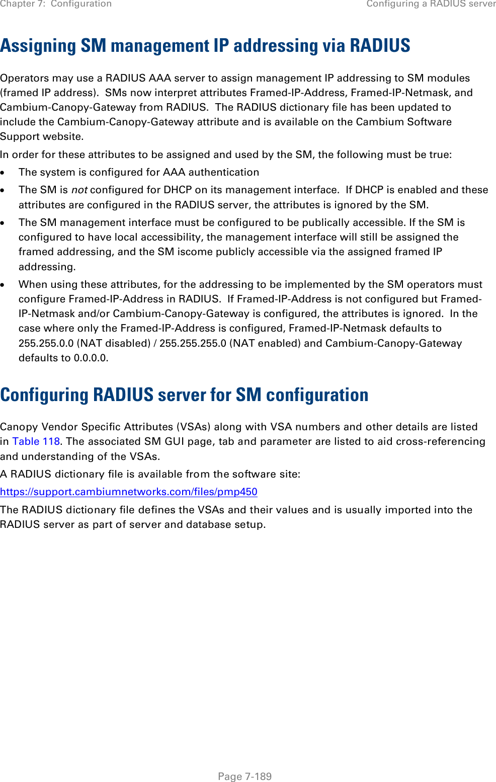
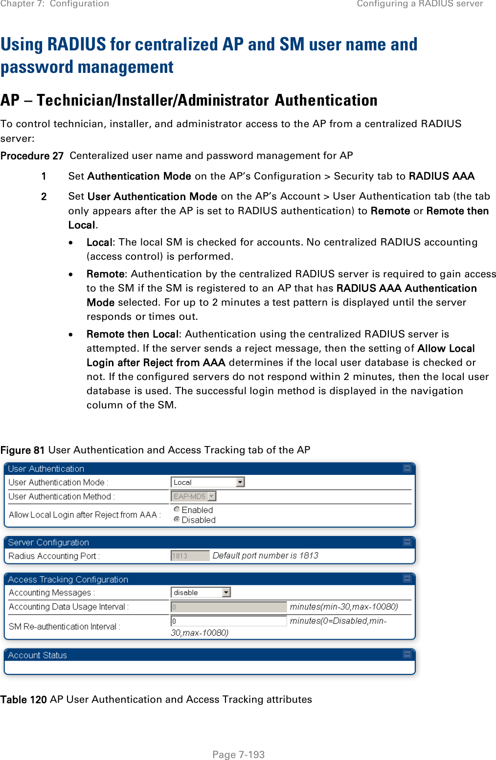
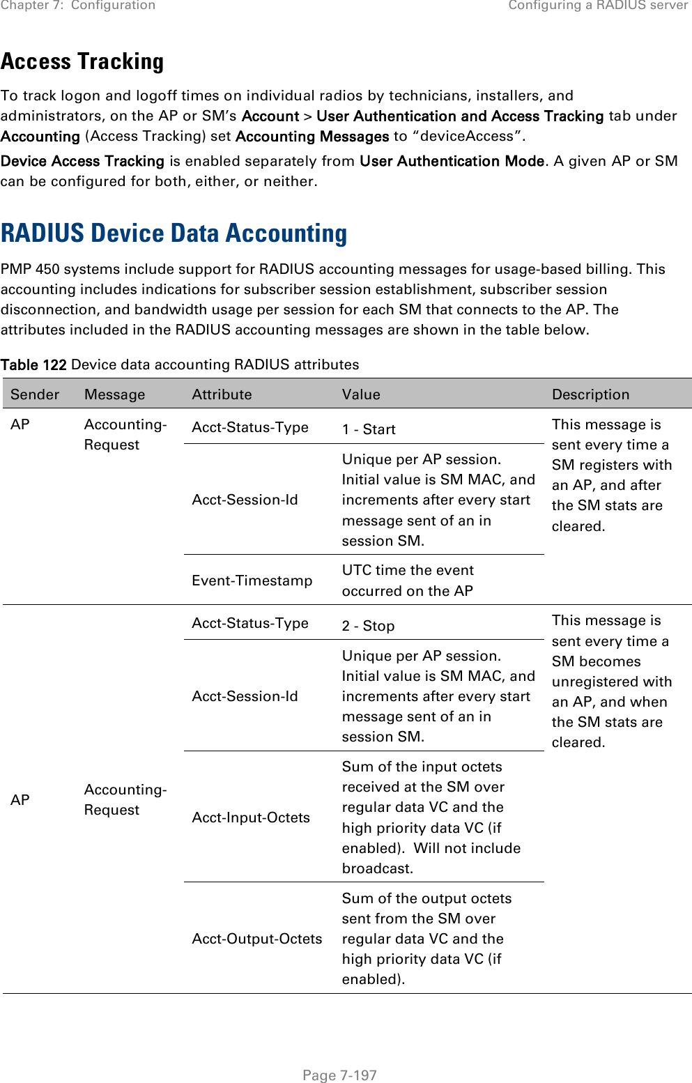
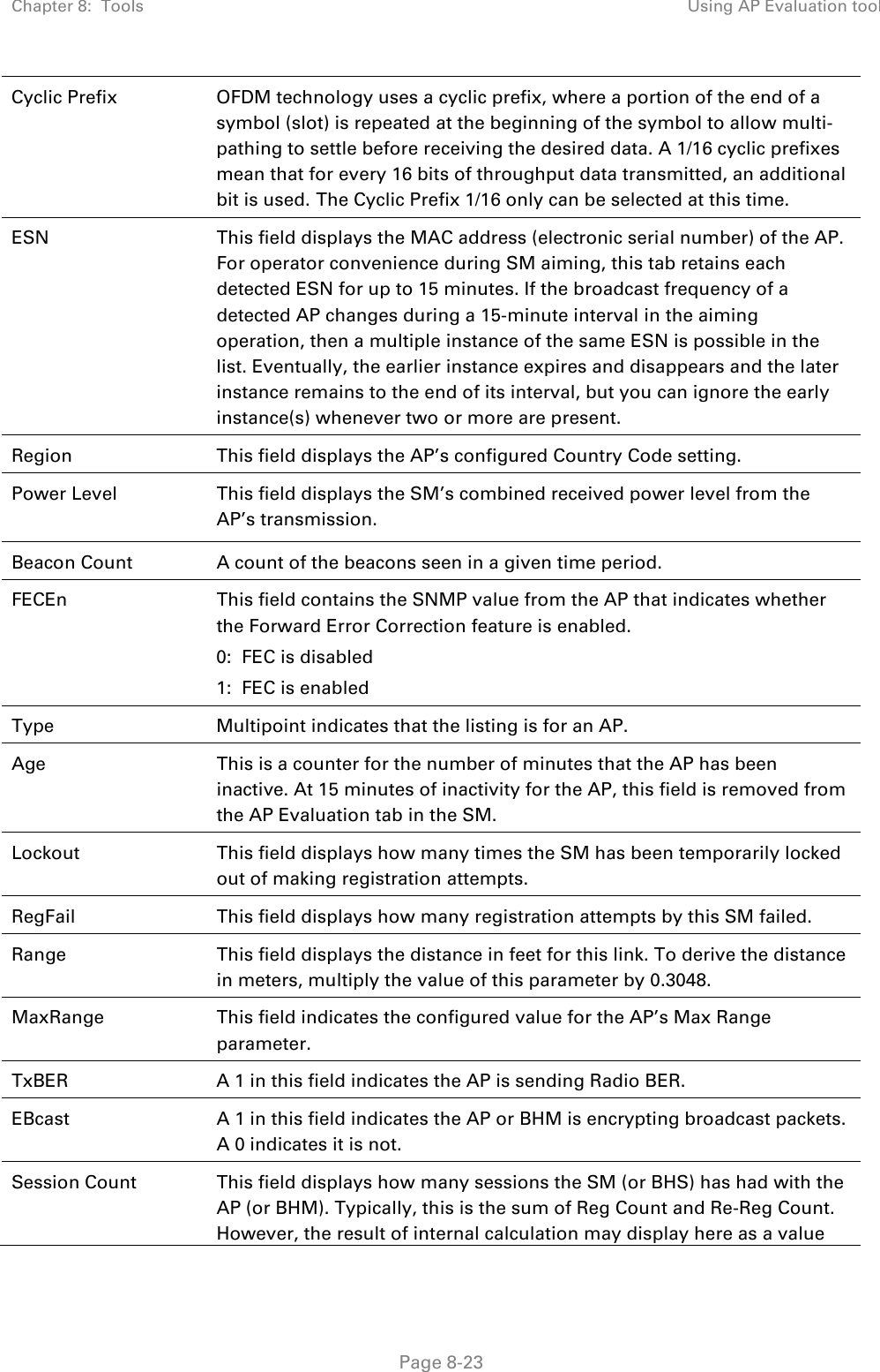
![Chapter 7: Configuration Zero Touch Configuration Using DHCP Option 66 Page 7-169 "frequencyScanList": [ 5475000, 5480000 ], "colorCodeList": [ { "colorCode": 42, "priority": 1 } ] }, "networkConfig": { "lanDhcpState": 1 } }, "cfgFileVersion": "1.0", "cfgFileString": "Canopy configuration file", "configFileParameters": { "rebootIfRequired": true } } When configuration is imported, only the items that exist in the configuration file are modified. Parameters that are not in the imported file are not changed. If user wish to revert those settings to their factory default values, please add a “setToDefaults” item under “configFileParameters” section with a value of true. "cfgFileVersion": "1.0", "cfgFileString": "Canopy configuration file", "configFileParameters": { "rebootIfRequired": true, "setToDefaults": true } In case, the SM needs to fetch the configuration file on each boot up even when not connecting to AP via ICC, set “Network Accessibility” to “Public” and “DHCP State” to “Enabled” in the “Configuration > IP” page before exporting the configuration. Hosting the config file Copy the golden configuration file to an FTP, TFTP, HTTP or HTTPS server. This location can be password protected; you just have to include the user name and password in the URL. DHCP server configuration Configure DHCP server to return the full URL to the golden config file as the value of DHCP option 66.](https://usermanual.wiki/Cambium-Networks/50450I.User-Guide-Part-4/User-Guide-2762119-Page-63.png)
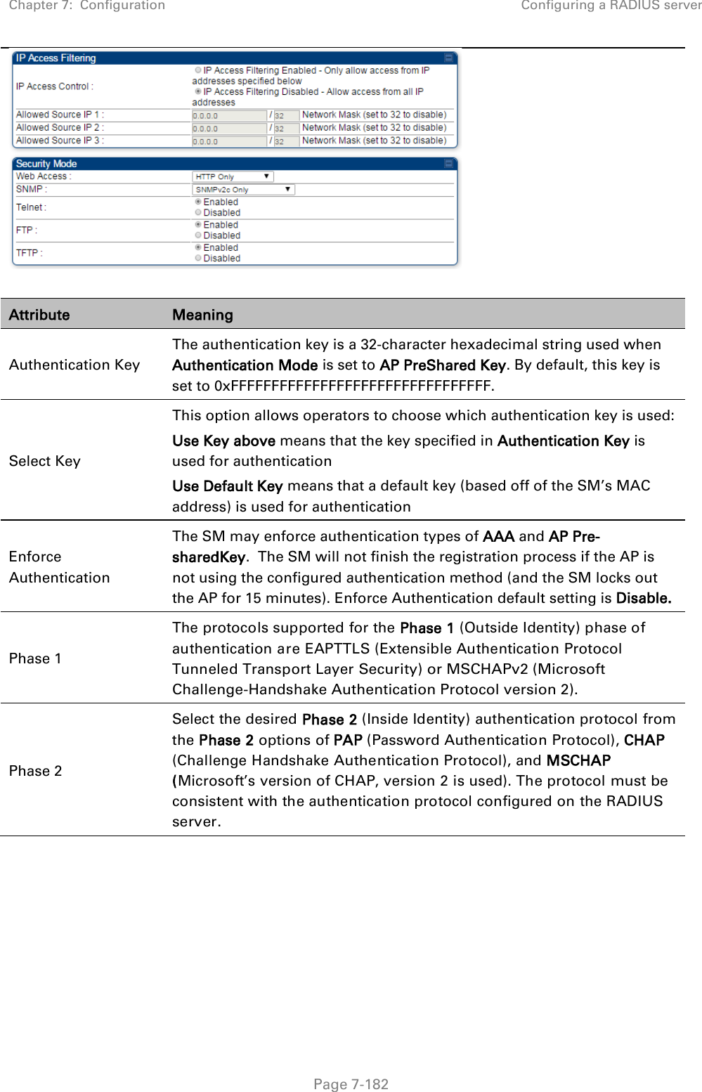
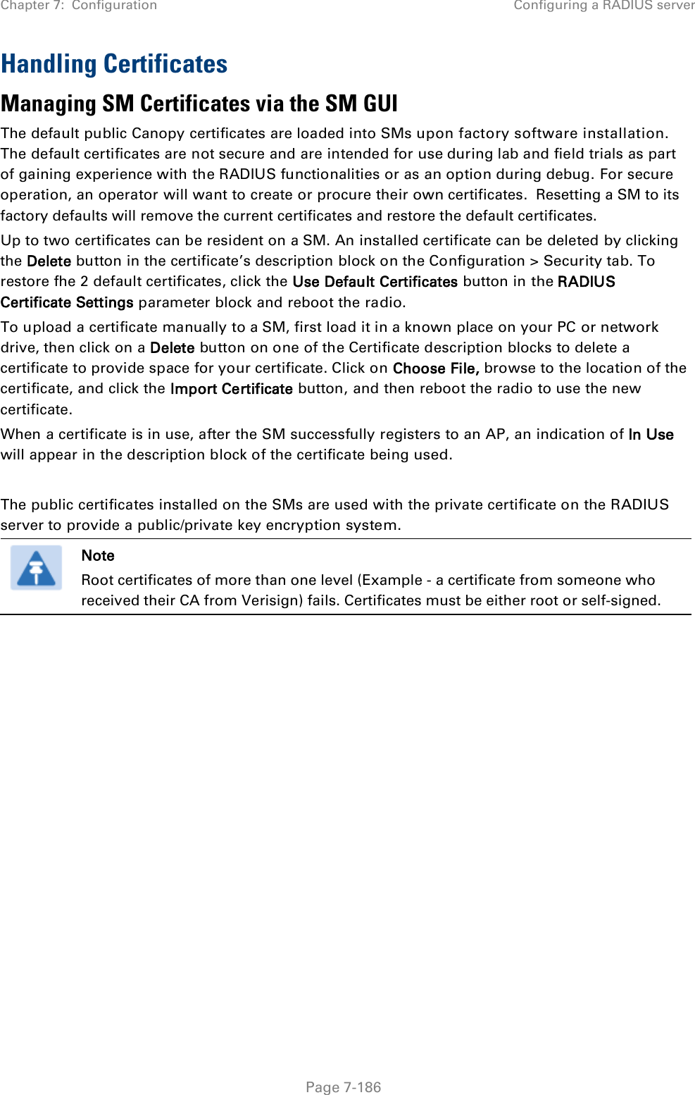
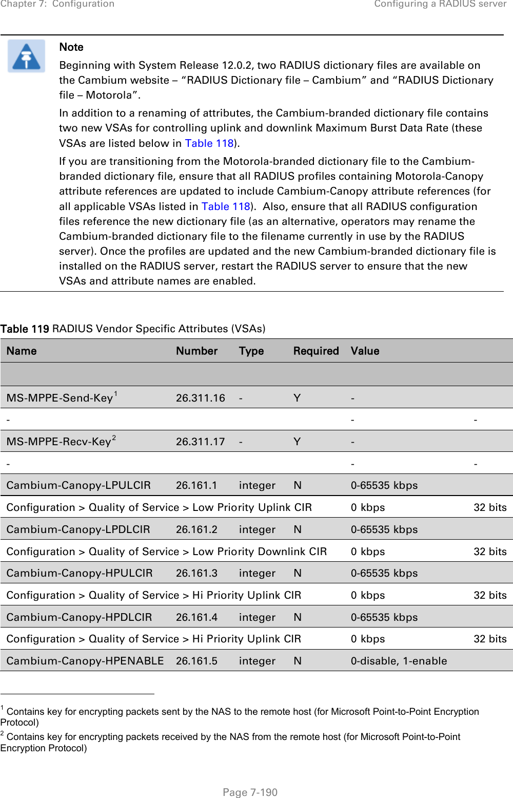
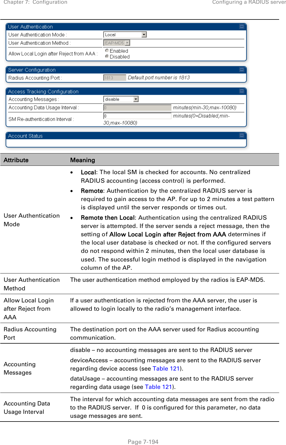
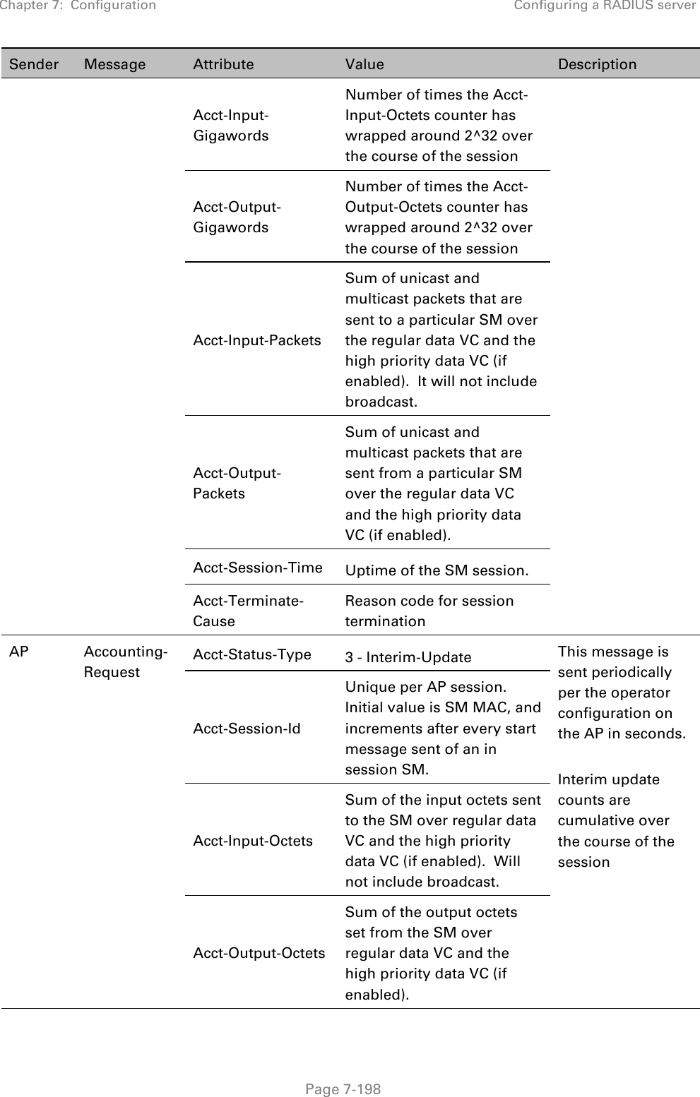


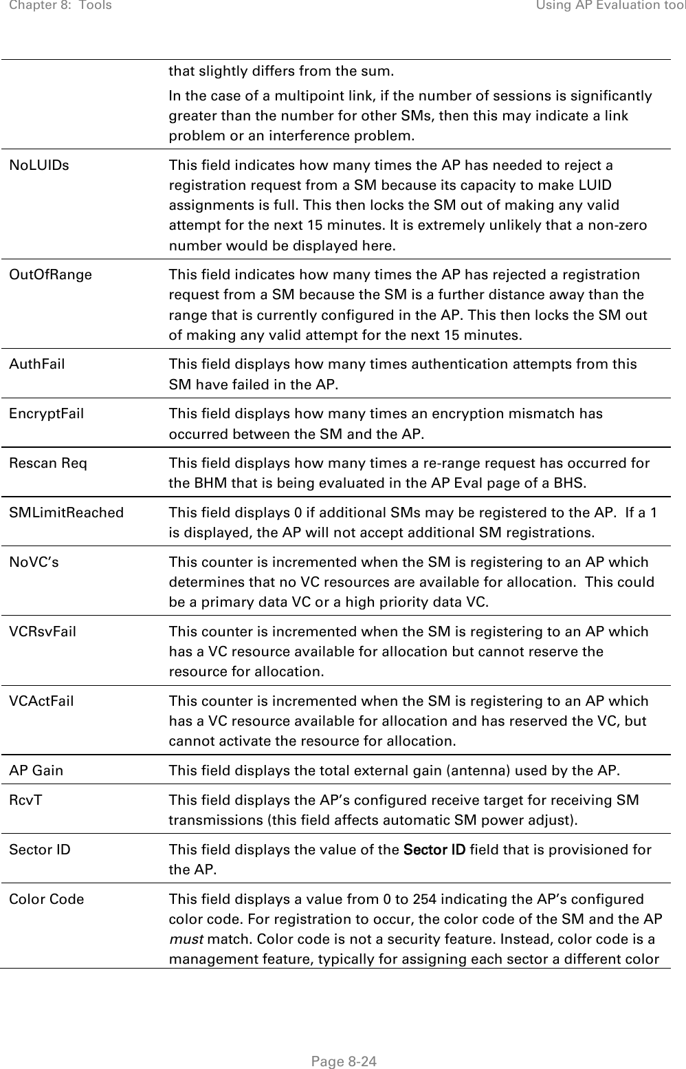
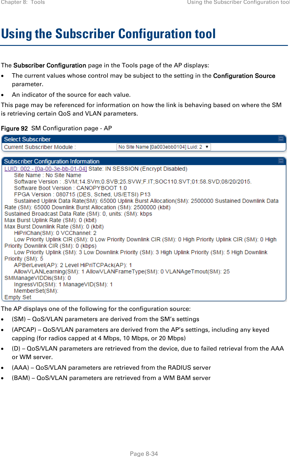
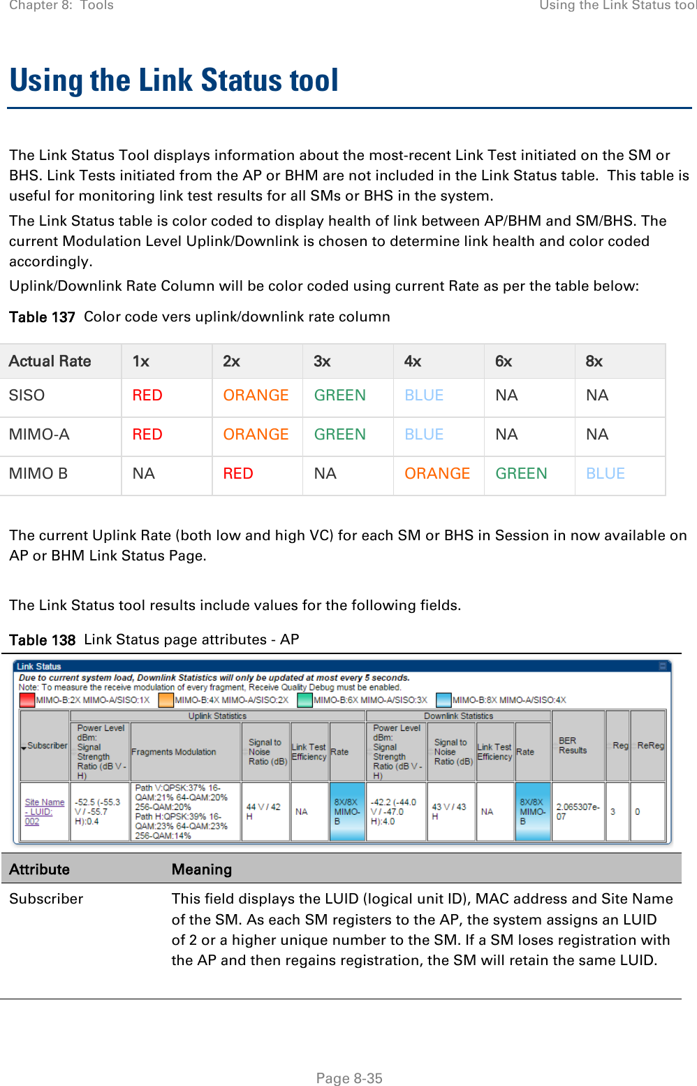
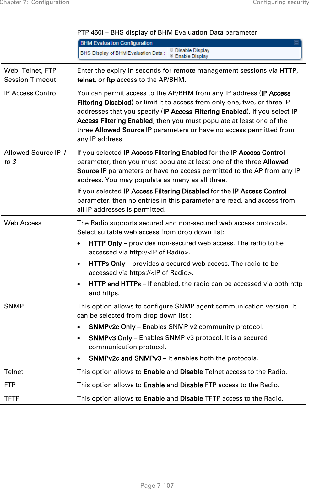
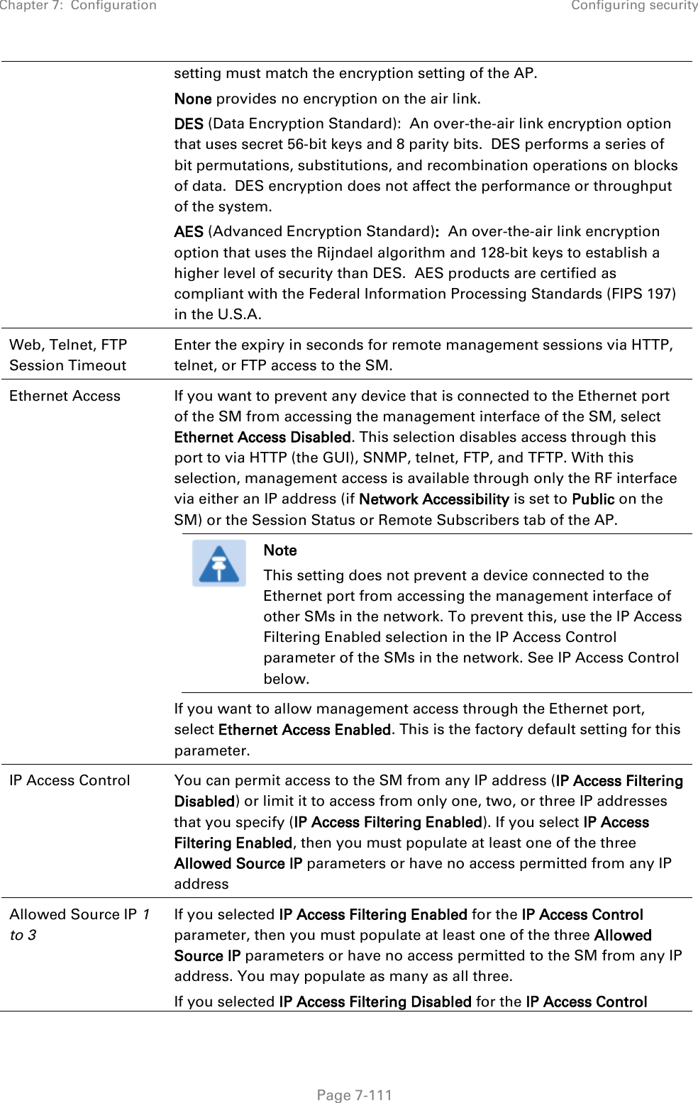
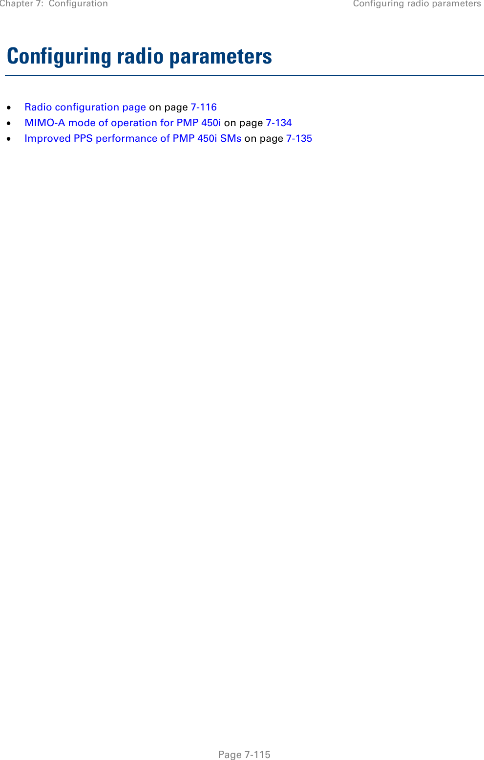
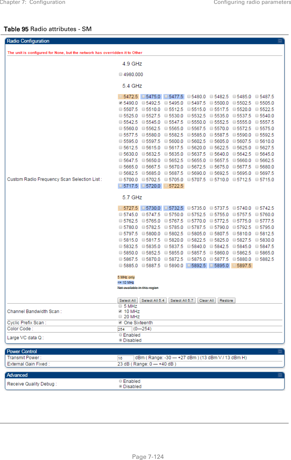
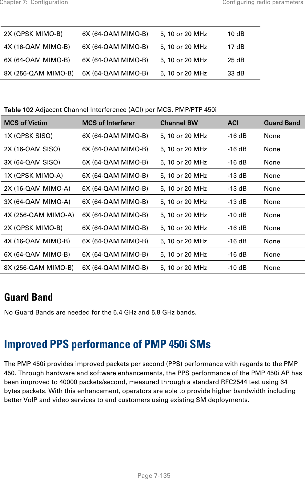
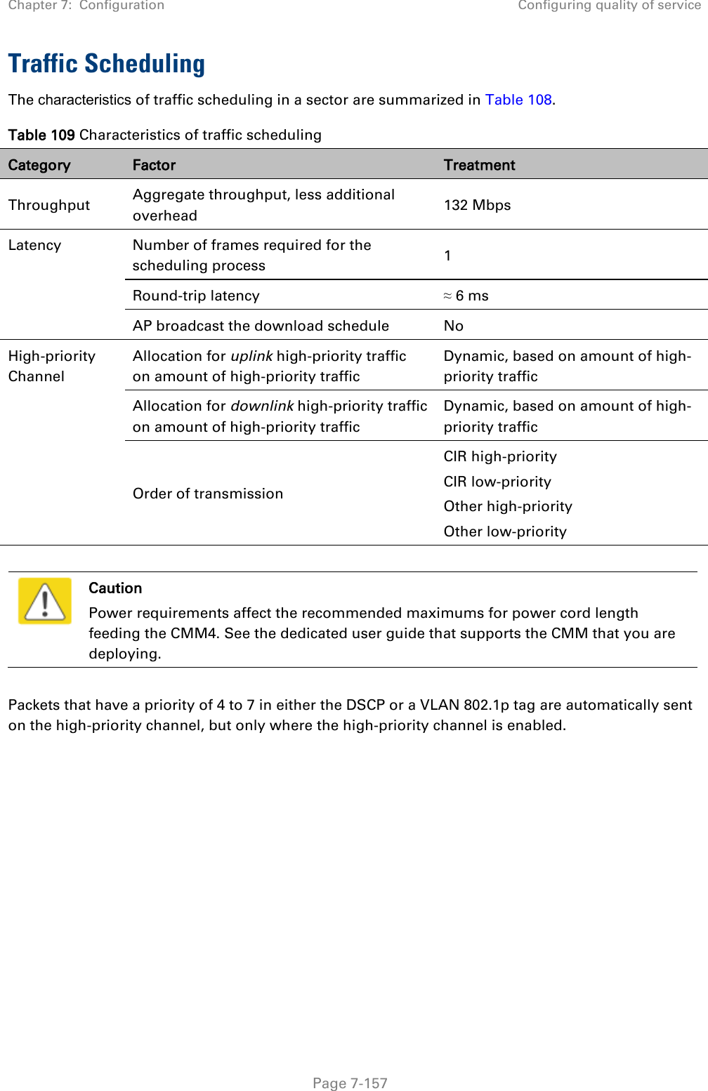
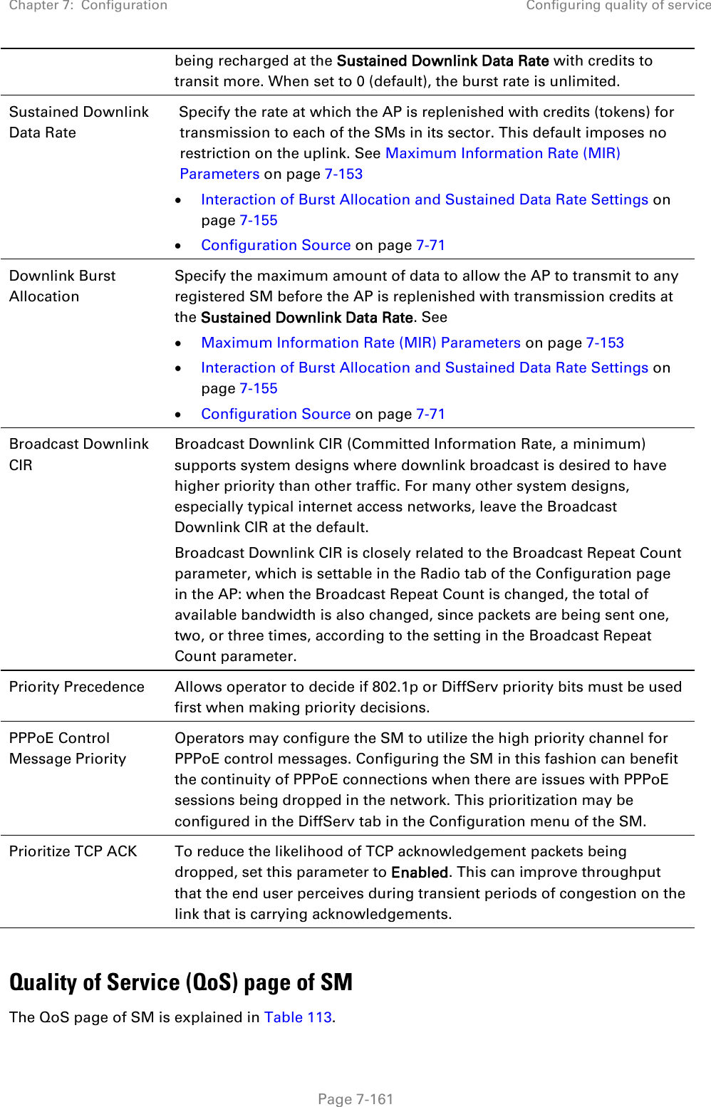
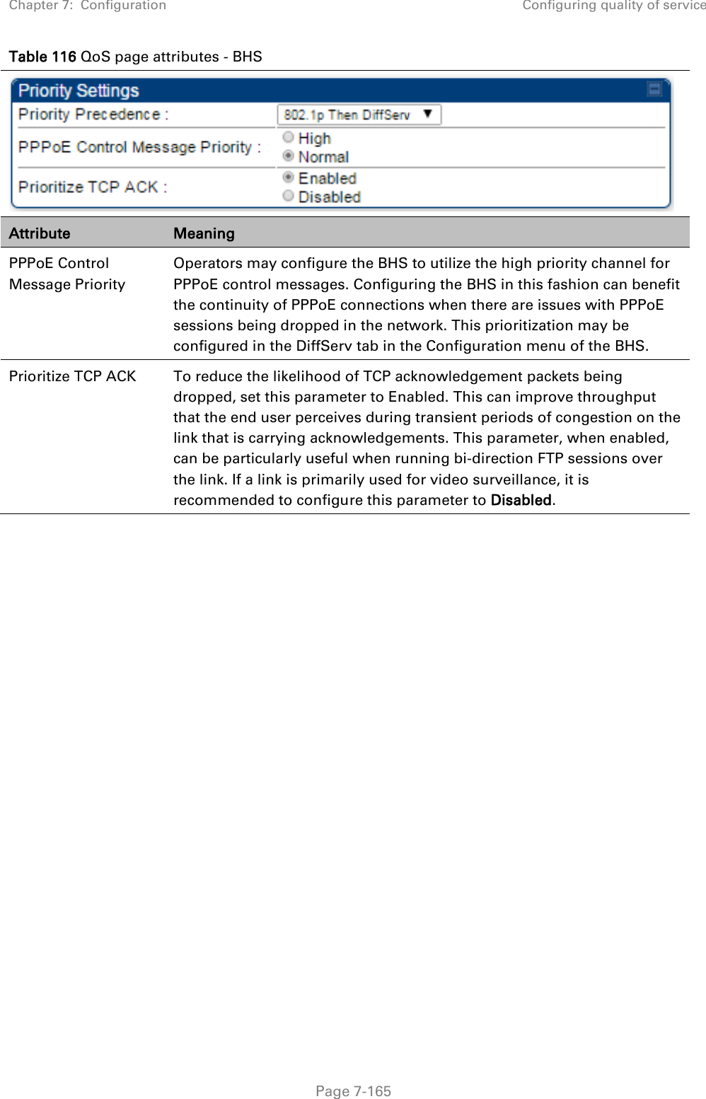
![Chapter 8: Tools Using the Link Status tool Page 8-36 Note The LUID associated is lost when a power cycle of the AP occurs. Both the LUID and the MAC are hot links to open the interface to the SM. In some instances, depending on network activity and network design, this route to the interface yields a blank web page. If this occurs, refresh your browser view. Site Name indicates the name of the SM. You can assign or change this name on the Configuration web page of the SM. This information is also set into the sysName SNMP MIB-II object and can be polled by an SNMP management server. Uplink Statistics - Power Level: Signal Strength Ratio This field represents the combined received power level at the AP/BHM as well as the ratio of horizontal path signal strength to vertical path signal strength. Uplink Statistics – Fragments Modulation This field represents the percentage of fragments received at each modulation state, per path (polarization). Uplink Statistics – Signal to Noise Ratio This field represents the signal to noise ratio for the uplink (displayed when parameter Signal to Noise Ratio Calculation during Link Test is enabled) expressed for both the horizontal and vertical channels. Uplink Statistics – Link Test Efficiency This field displays the efficiency of the radio link, expressed as a percentage, for the radio uplink. Downlink Statistics – Power Level: Signal Strength Ratio This field represents the received power level at the SM/BHS as well as the ratio of horizontal path signal strength to vertical path signal strength at the SM/BHS. Downlink Statistics – Signal to Noise Ratio This field represents the signal to noise ratio for the downlink (displayed when parameter Signal to Noise Ratio Calculation during Link Test is enabled) expressed for both the horizontal and vertical channels. Downlink Statistics – Link Test Efficiency This field displays the efficiency of the radio link, expressed as a percentage, for the radio downlink. BER Results This field displays the over-the-air Bit Error Rates for each downlink. (The ARQ [Automatic Resend reQuest] ensures that the transport BER [the BER seen end-to-end through a network] is essentially zero.) The level of acceptable over-the-air BER varies, based on operating requirements, but a reasonable value for a good link is a BER of 1e-4 (1 x 10⁻⁴) or better, approximately a packet resend rate of 5%. BER is generated using unused bits in the downlink. During periods of peak load, BER data is not updated as often, because the system puts priority on transport rather than on BER calculation.](https://usermanual.wiki/Cambium-Networks/50450I.User-Guide-Part-4/User-Guide-2762119-Page-130.png)