CalAmp 55BTW Broadband router to enable wireless data connectivity. User Manual II
CalAmp Broadband router to enable wireless data connectivity. II
UserManual.wiki
>
CalAmp
>
55BTW User Manual
>
User Manual II
Contents
1.
User Manual I
2.
User Manual II
User Manual II
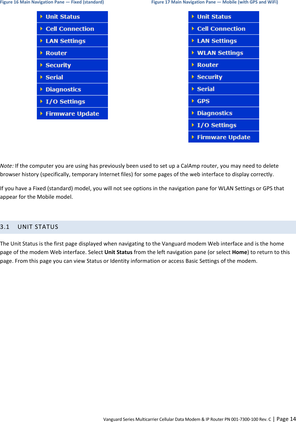
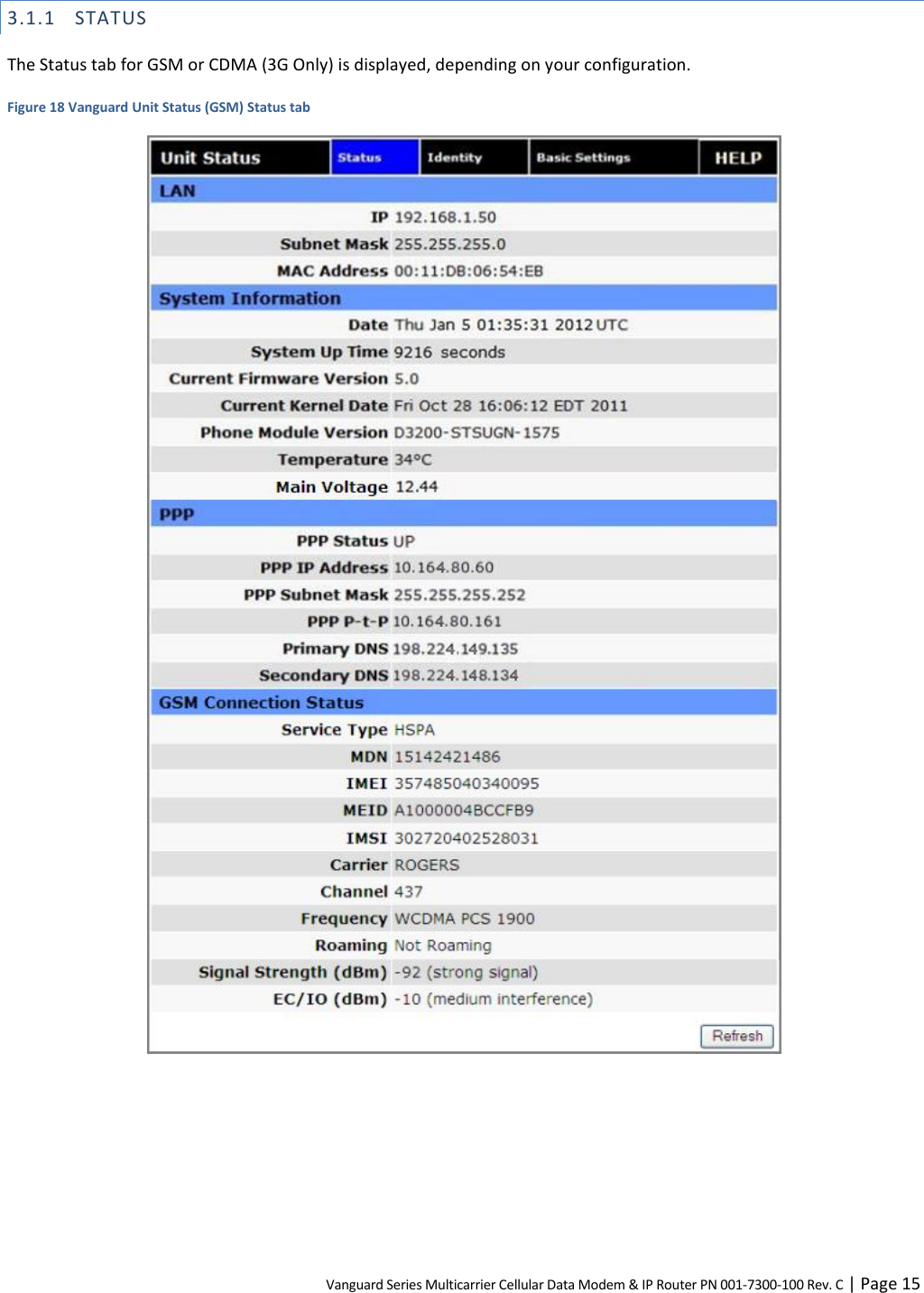
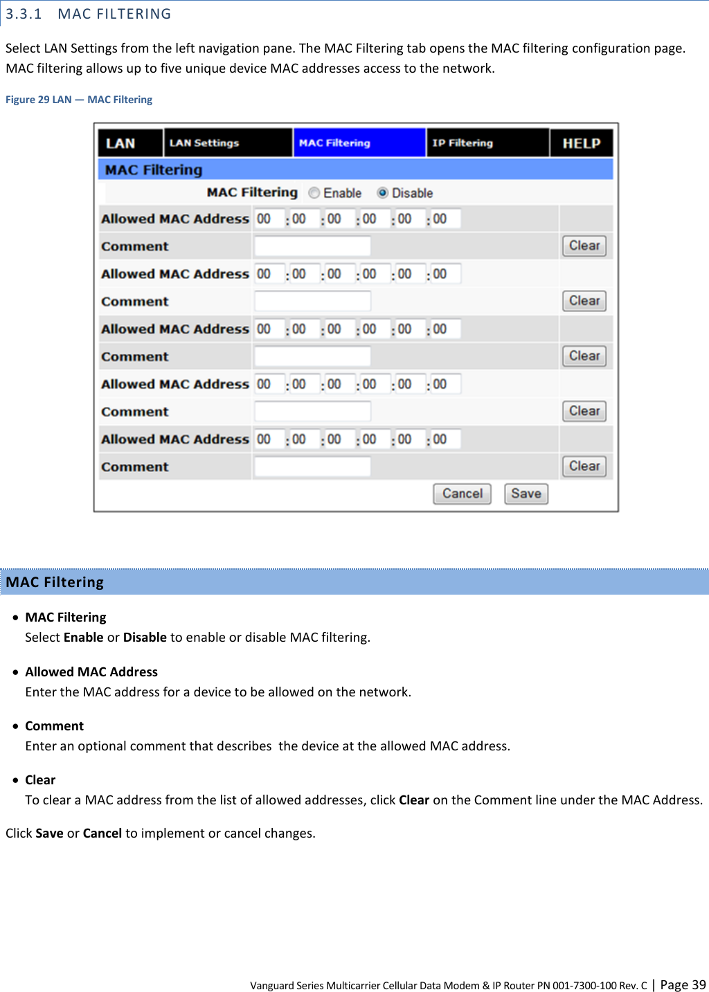
Navigation menu
Upload a User Manual
Namespaces
Wiki Guide
HTML
PDF
Info
Views
User Manual
Discussion / Help
Navigation
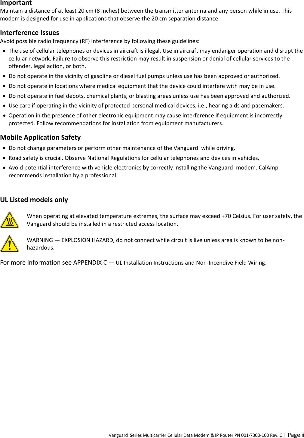
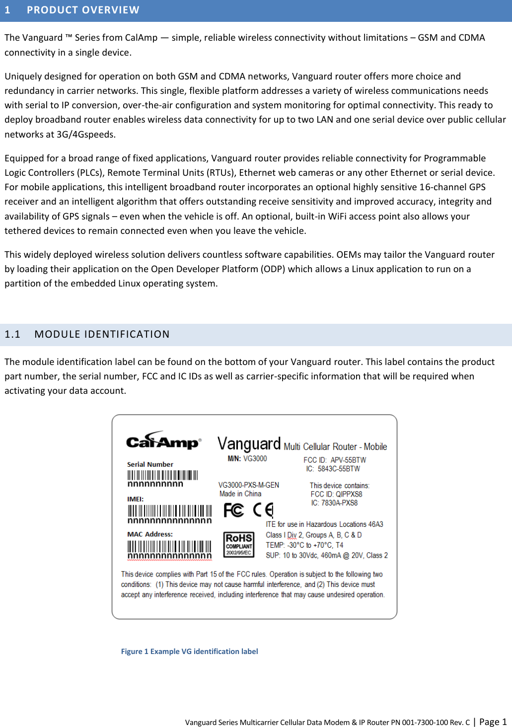


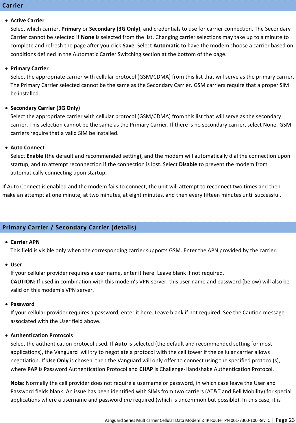
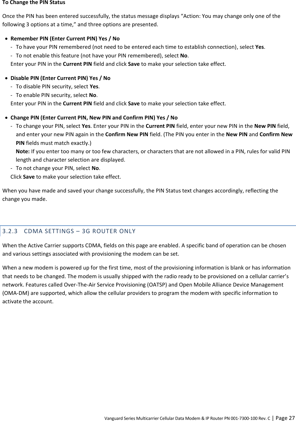
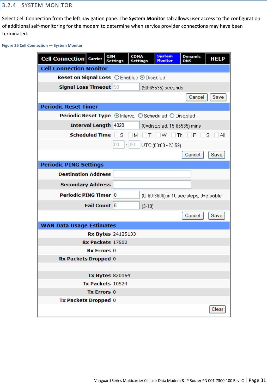
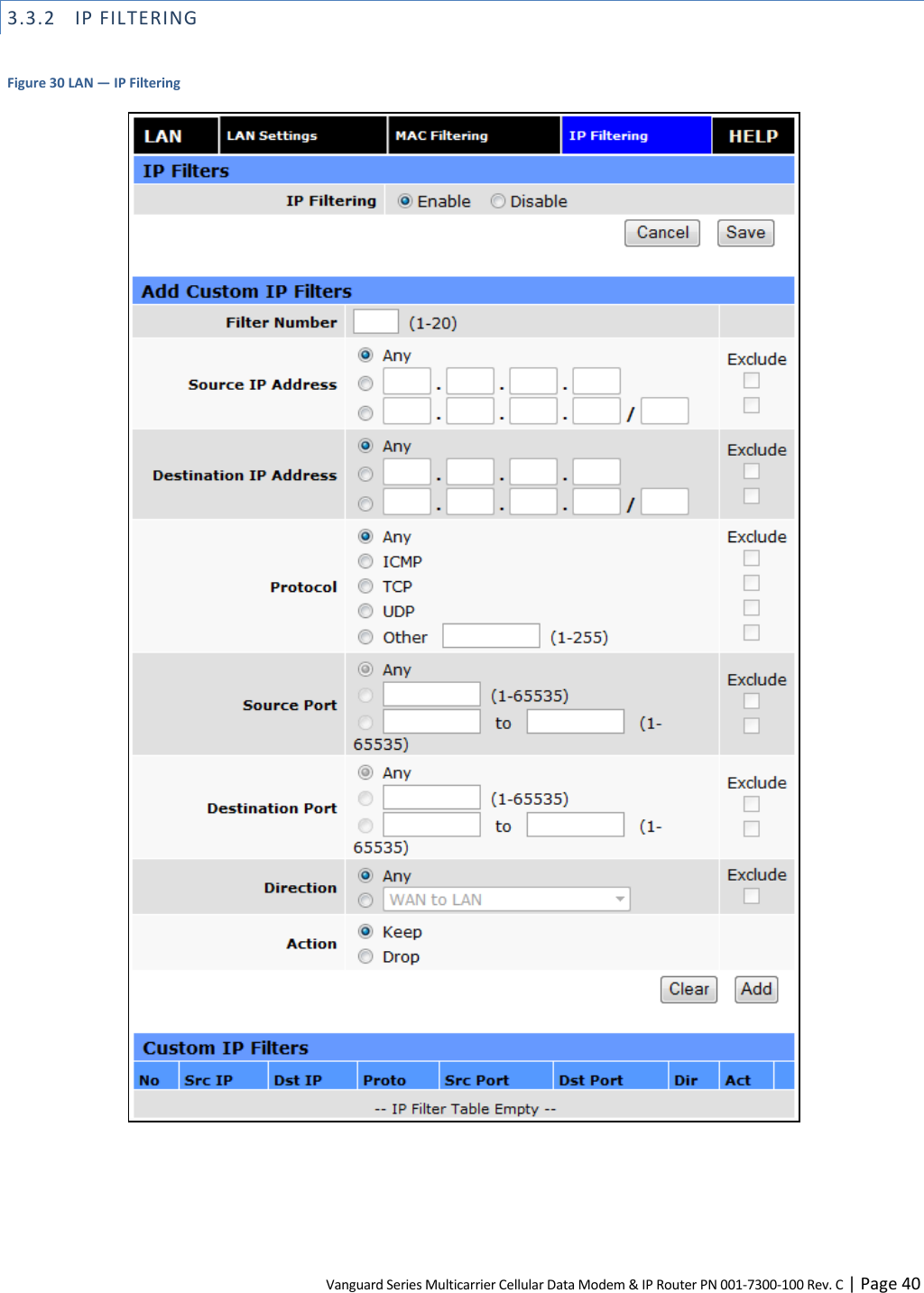
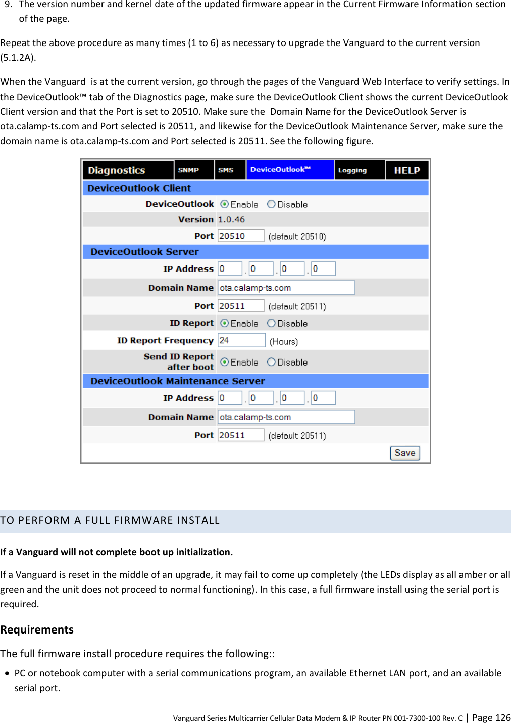
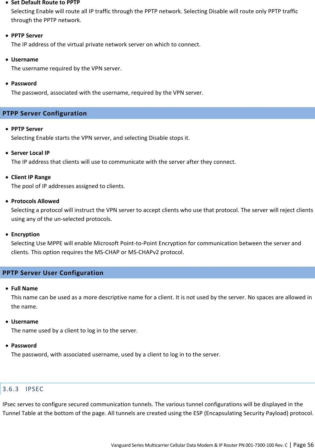
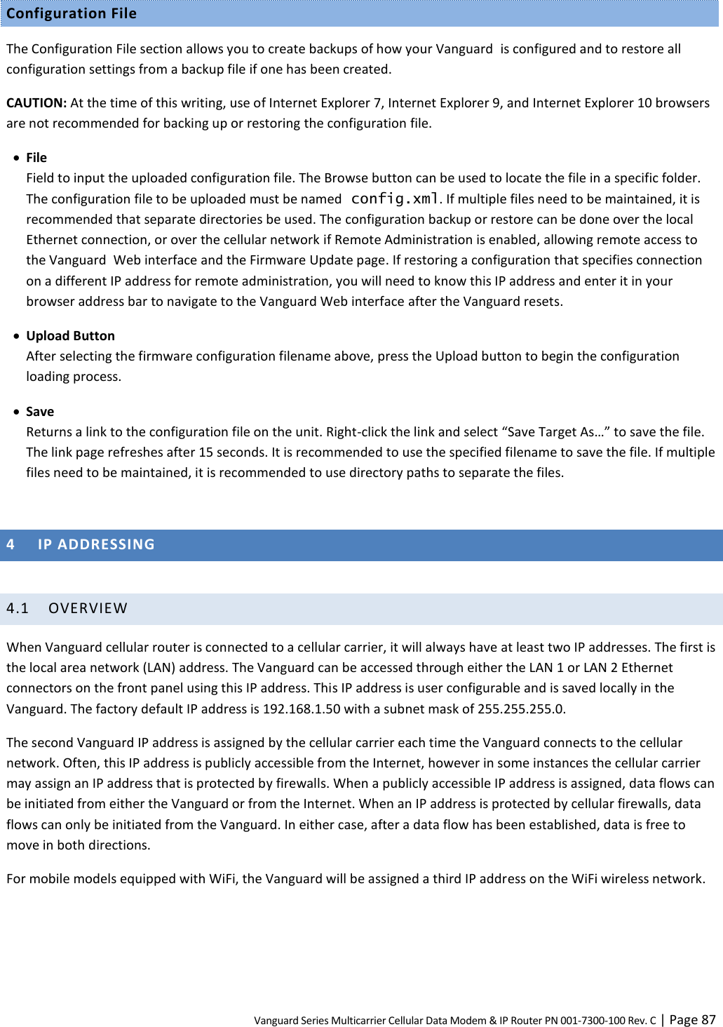
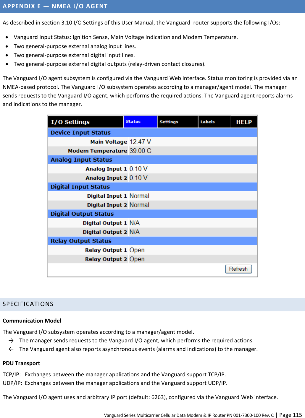
![Vanguard Series Multicarrier Cellular Data Modem & IP Router PN 001-7300-100 Rev. C | Page 41 The "IP Filtering" page is used to configure IP filters. The user can enter up to 20 IP filters. Each IP filter is identified by a unique number (from 1 to 20). An IP packet goes through the filtering logic when IP filtering is enabled and: 1) An IP packet is received on one of the interfaces and is destined to the Vanguard unit OR 2) An IP packet is sent by the Vanguard unit OR 3) An IP packet is forwarded by the Vanguard unit. The filtering logic is the following: if exists(filter[1]) AND match(packet, filter[1]) then apply(action[1]) else if exists(filter[2]) AND match(packet, filter[2]) then apply(action[2]) else if exists(filter[3]) AND match(packet, filter[3]) then apply(action[3]) else if exists(filter[20]) AND match(packet, filter[20]) then apply(action[20]) else process packet normally. Where: exists(filter[n]) -> The user as defined filter number n. match(packet, filter[n]) -> The IP packet matches filter number n. apply(action[n]) -> The action identified in filter number n. IP Filters IP Filtering Enable: IP filtering is enabled. Any custom IP filters entered by the user will be taken into account when processing IP packets. The predefined IP filters will also be taken into account. Disable: IP filtering is disabled. Add Custom IP Filters Filter Number Each IP filter is identified by a unique number from 1 to 20. Note that if you enter a filter number that is already in use, the new filter will overwrite the old filter with no warning or confirmation. Source IP Address Any: Any source IP Address will satisfy this criteria. Specific: A specific Host IP address. Range: A range of IP addresses. If the Exclude field is checked, it means that in order for the packet to match with this criteria, it must NOT have this source IP address (or NOT be in the given source IP address range).](https://usermanual.wiki/CalAmp/55BTW.User-Manual-II/User-Guide-2449452-Page-48.png)
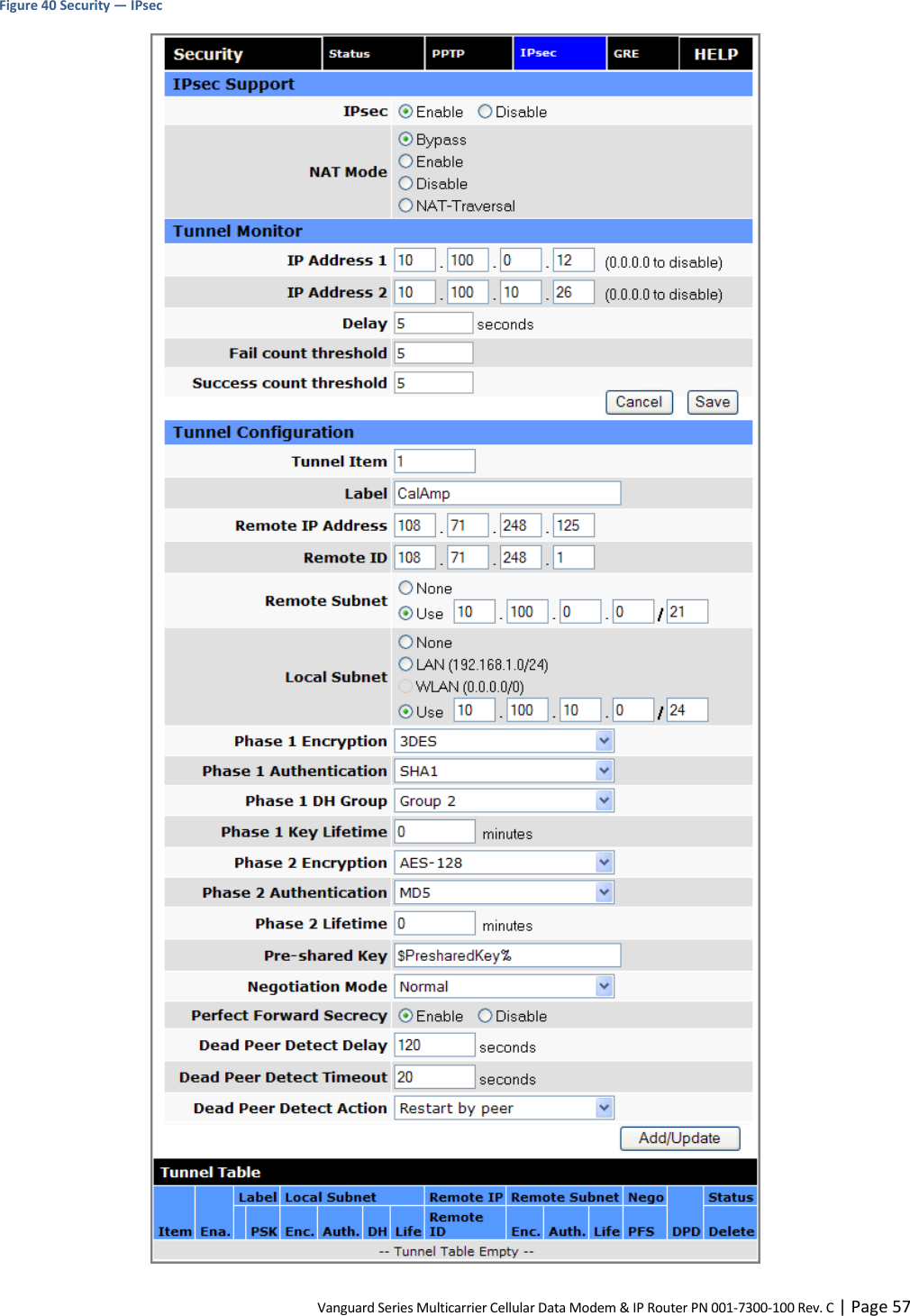
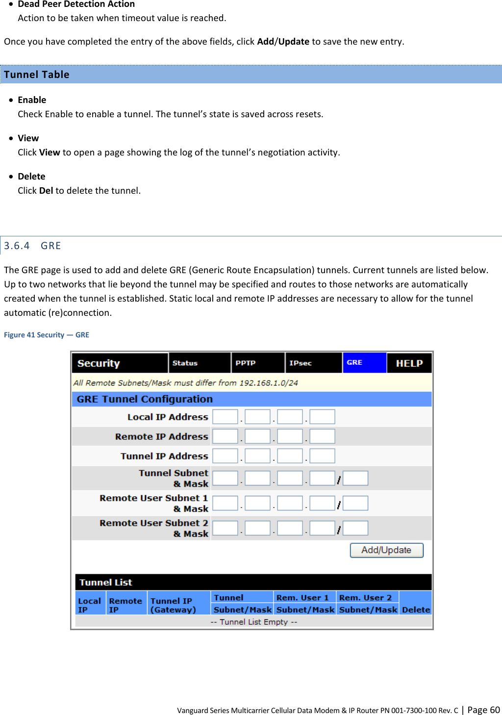
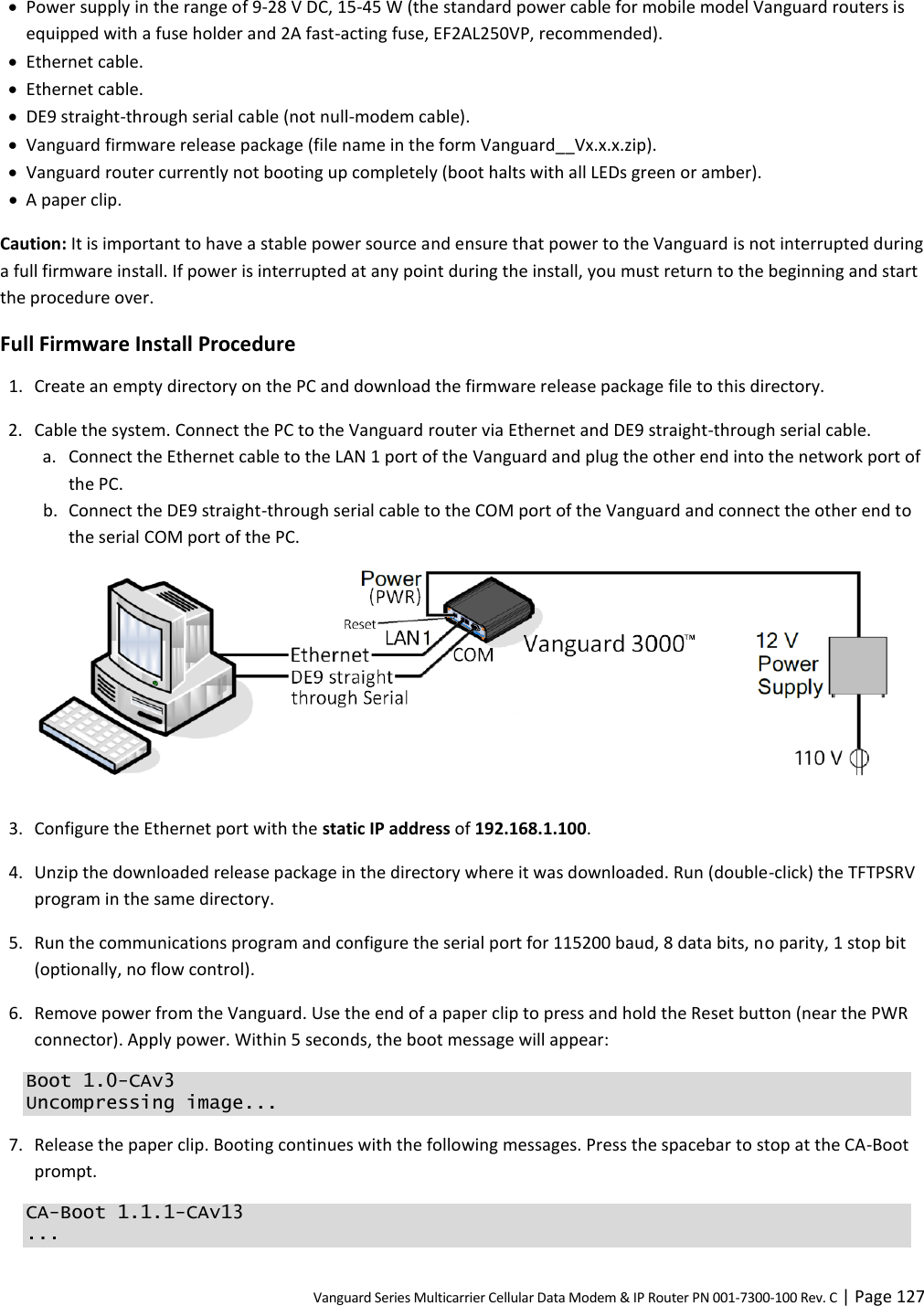
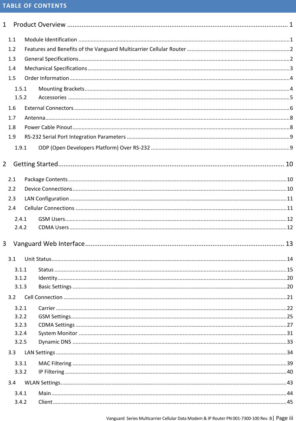
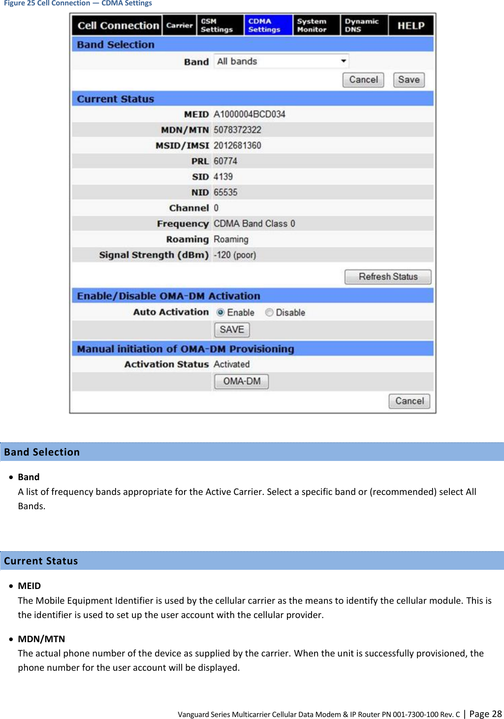
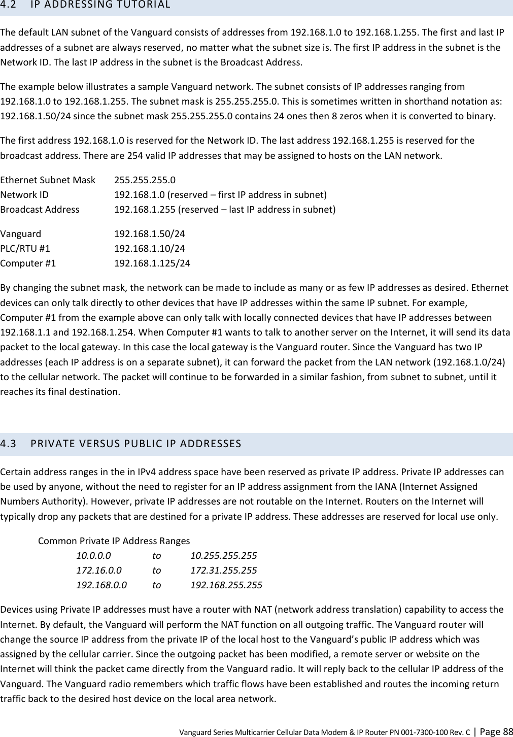
![Vanguard Series Multicarrier Cellular Data Modem & IP Router PN 001-7300-100 Rev. C | Page 61 GRE Tunnel Configuration Local IP Address The local (normally WAN interface) IP address associated with the tunnel. Remote IP Address The remote IP address associated with the tunnel. Tunnel IP Address The IP address assigned to the tunnel interface. [ Example: 192.168.10.100 ] Tunnel Subnet & Mask The tunnel subnet and mask that must include the above Tunnel IP Address. [ Example: 192.168.10.0/24 ] Remote User Subnet 1 & Mask The IP network representing that of the remote user subnet, accessible via the tunnel. [ Example: 192.168.20.0/24 ] Remote User Subnet 2 & Mask A possible second IP network representing another remote user subnet. [ Example: 192.168.15.0/24 ] Note: All subnets must differ from one another and must not overlap. If more than two remote user subnets are necessary, additional routes can be setup manually via the Router » Static Routes tab using the Tunnel IP Address as the gateway. 3.7 SERIAL From the main navigation pane, select Serial for access to both external and internal serial port configuration pages. 3.7.1 EXTERNAL SERIAL Use the External Serial tab to define and configure the functioning of the RS-232 Serial Port, which can be set to output GPS position reports or to function as a Packet Assembler and Disassembler (PAD), transferring all serial data to or from a specified TCP/UDP port.](https://usermanual.wiki/CalAmp/55BTW.User-Manual-II/User-Guide-2449452-Page-68.png)
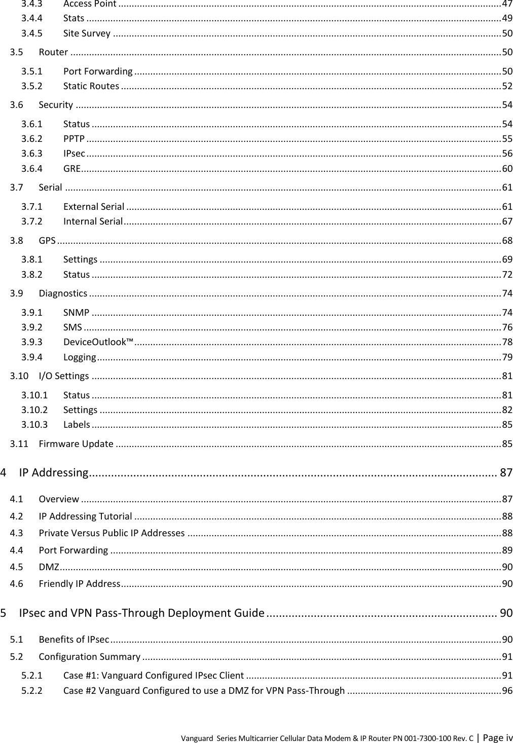
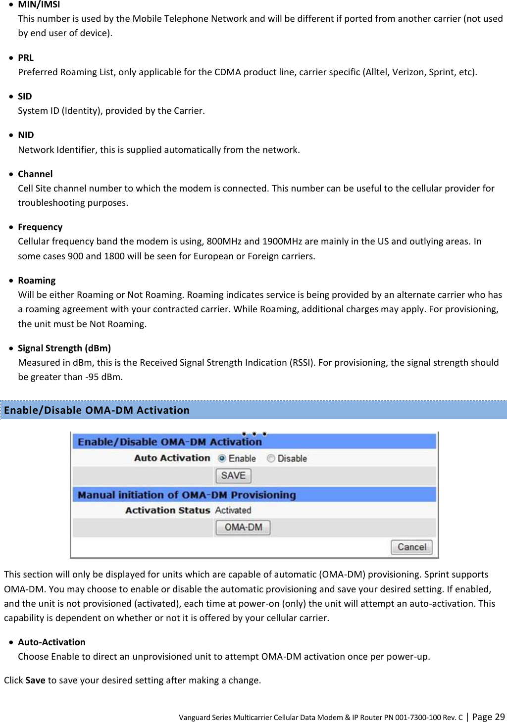
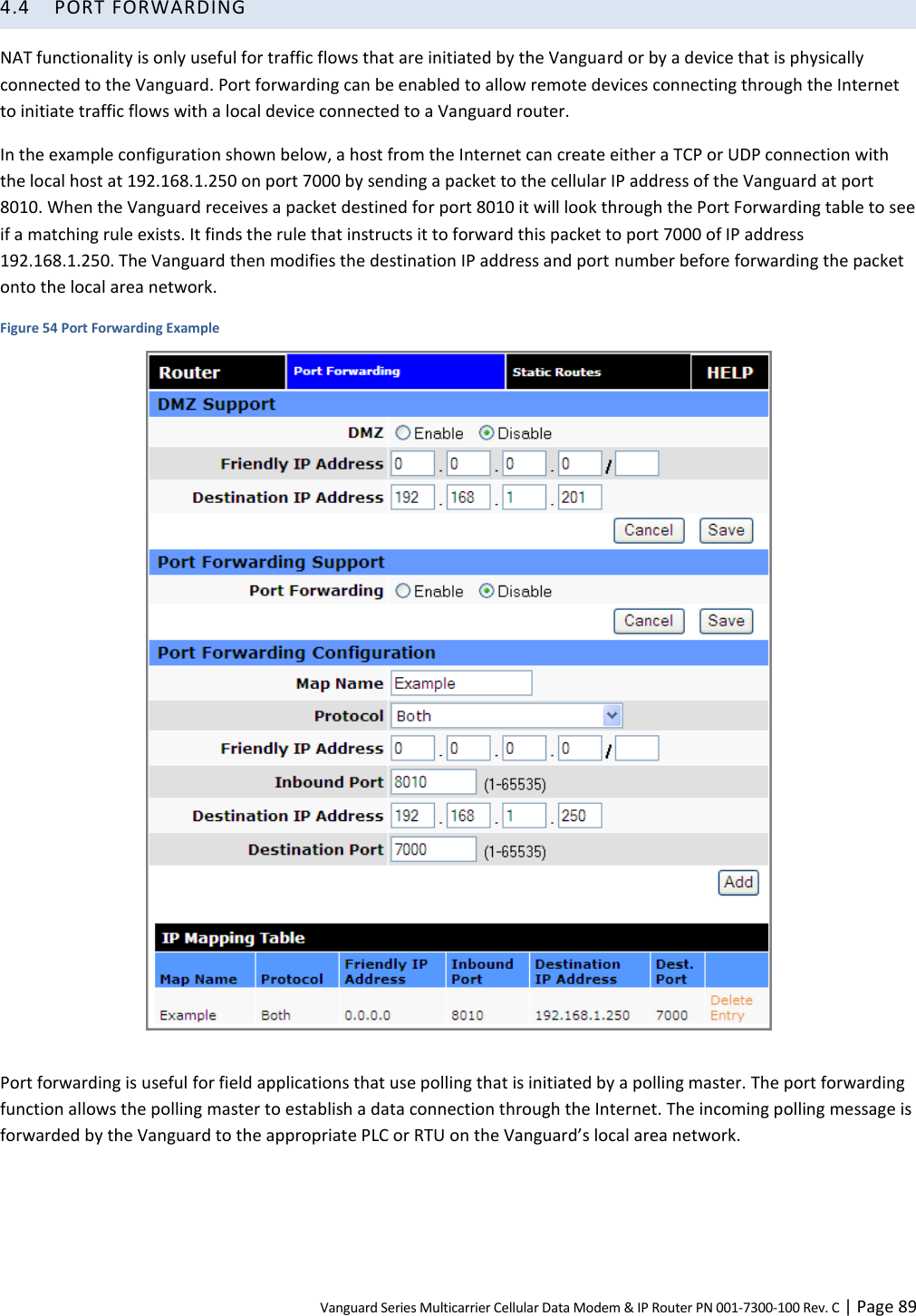
![Vanguard Series Multicarrier Cellular Data Modem & IP Router PN 001-7300-100 Rev. C | Page 76 3.9.2 SMS The SMS CLI (Command-Line Interface) allows a small set of commands to be sent to the Vanguard using SMS. More information about the Vanguard — SMS Interface is provided in APPENDIX D. Figure 47 Diagnostics – SMS All commands are prefixed with the slash “/” character. The supported commands are: /status [pw=password] Returns the following fields: WAN= DOWN or the IP address of the cellular connection RSSI= the signal strength of the cellular radio channel ECIO= the interference on the cellular radio channel PPTP= the state of the PPTP VPN: UP or DOWN IPSEC= the number of active / enabled / defined tunnels GPS= the latitude, longitude (in decimal degrees) of the modem V= the main voltage of the modem T= the temperature of the modem D1=, D2= the state of the twor digital inputs: 0 (inactive) or 1 (active) A1=, A2= the levels of the two analog inputs, in volts R1=, R2= the state of the two relay outputs: O (open) or C (closed) /pptpstart [pw=password] Starts the PPTP VPN. /pptpstop [pw=password] Stops the PPTP VPN. /ipsecstart [pw=password] tun=label Starts the IPsec tunnel that has the specified label. /ipsecstop [pw=password] tun=label Stops the IPsec tunnel that has the specified label.](https://usermanual.wiki/CalAmp/55BTW.User-Manual-II/User-Guide-2449452-Page-83.png)
![Vanguard Series Multicarrier Cellular Data Modem & IP Router PN 001-7300-100 Rev. C | Page 77 /output [pw=password] m=v … Controls the relay outputs, where: r is “r”, “rly”, or “relay”; n is “1” or “2”; v is “0”, “o”, or “open” to open; “1”, “c”, “close”, or “closed” to close. r and v can be in any case, upper or lower. Both relays can be set from one command. SMS Commands SMS Commands – Enable allows the Vanguard to respond to received SMS commands. – Disable causes SMS messages (that start with a slash) to be accepted but quietly discarded. Password In nonblank, all commands require the password in the form pw=password as one of the arguments. The pw prefix can occur in any case (“pw=”, “PW=”, “Pw=”, etc.) but the password must be in the exact case as entered on the web page. Allowed Senders Sender 1 / Sender 2 / Sender 3 Commands can be restricted to be accepted only if they arrive from one of up to three “friendly” SMS Sender addresses. Sender addresses are typically numeric digits only including the country code prefix. The check box in front of each Sender address can be used to enable or disable the address entered in the adjacent field. If all three addresses are disabled, then commands will be accepted from ALL senders. Respond only to Senders For security, command responses, including error messages, can be restricted to be returned only to the registered Sender SMS addresses.](https://usermanual.wiki/CalAmp/55BTW.User-Manual-II/User-Guide-2449452-Page-84.png)
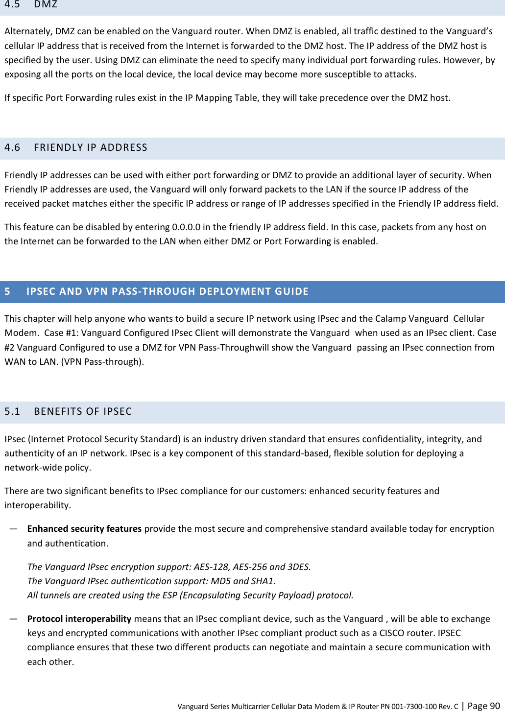
![Vanguard Series Multicarrier Cellular Data Modem & IP Router PN 001-7300-100 Rev. C | Page 94 After the page refreshes, the tunnel configuration will appear in the Tunnel Table at the bottom of the tab. It will not be enabled automatically, however. Step 6 To enable the IPsec tunnel, check the “Ena.” check box associated with the tunnel and allow for the page to refresh. Step 7 When the IPsec tunnel is established, all IP Packet traffic originating from 192. 32. 8.254/32 will pass through the IPsec VPN tunnel to the local subnet (10.192.10.192/29), and vice-versa. Click the View link in the far-right column of the table to monitor the IPsec client connection. A window opens to display the log of the tunnel’s negotiation activity (early events appear near the top and more-recent events appear near the bottom). Search the log contents for “IPsec SA established tunnel mode.” 002 "ttunnel1" #1: initiating Main Mode 104 "ttunnel1" #1: STATE_MAIN_I1: initiate 003 "ttunnel1" #1: ignoring Vendor ID payload [FRAGMENTATION c0000000] 002 "ttunnel1" #1: transition from state STATE_MAIN_I1 to state STATE_MAIN_I2 106 "ttunnel1" #1: STATE_MAIN_I2: sent MI2, expecting MR2 003 "ttunnel1" #1: received Vendor ID payload [Cisco-Unity] 003 "ttunnel1" #1: received Vendor ID payload [XAUTH] 003 "ttunnel1" #1: ignoring unknown Vendor ID payload [d194db099684f49320f6abd9829c7b65] 003 "ttunnel1" #1: ignoring Vendor ID payload [Cisco VPN Series] 002 "ttunnel1" #1: transition from state STATE_MAIN_I2 to state STATE_MAIN_I3 108 "ttunnel1" #1: STATE_MAIN_I3: sent MI3, expecting MR3 003 "ttunnel1" #1: received Vendor ID payload [Dead Peer Detection] 002 "ttunnel1" #1: Main mode peer ID is ID_IPV4_ADDR: '10.168.86.192' 002 "ttunnel1" #1: transition from state STATE_MAIN_I3 to state STATE_MAIN_I4 004 "ttunnel1" #1: STATE_MAIN_I4: ISAKMP SA established {auth=OAKLEY_PRESHARED_KEY cipher=oakley_3des_cbc_192 prf=oakley_md5 group=modp1024} 002 "ttunnel1" #1: Dead Peer Detection (RFC 3706): enabled 002 "ttunnel1" #2: initiating Quick Mode PSK+ENCRYPT+TUNNEL+UP+IKEv2ALLOW {using isakmp#1 msgid:4328edc8 proposal=3DES(3)_192-MD5(1)_128 pfsgroup=no-pfs} 117 "ttunnel1" #2: STATE_QUICK_I1: initiate 003 "ttunnel1" #2: ignoring informational payload, type IPSEC_RESPONDER_LIFETIME msgid=4328edc8 002 "ttunnel1" #2: Dead Peer Detection (RFC 3706): enabled 002 "ttunnel1" #2: transition from state STATE_QUICK_I1 to state STATE_QUICK_I2 004 "ttunnel1" #2: STATE_QUICK_I2: sent QI2, IPsec SA established tunnel mode {ESP=>0x8e426351 <0xaeeb3b44 xfrm=3DES_0-HMAC_MD5 NATOA=none NATD=none DPD=enabled}](https://usermanual.wiki/CalAmp/55BTW.User-Manual-II/User-Guide-2449452-Page-101.png)
![Vanguard Series Multicarrier Cellular Data Modem & IP Router PN 001-7300-100 Rev. C | Page 95 Step 8 Once the “IPsec SA established tunnel mode” message is displayed in the tunnel negotiation log, a communication test is required to ensure point-to-point connectivity. From the Application Server located behind the VPN server, ping the LAN IP of the local device connected to the Vanguard LAN port. The pings should receive replies from the local device. Alternatively, ping the Application Server IP Address from a device on the Vanguard’s local LAN and receive replies similar to the following. [Prompt]$ping 192.32.8.254 PING 192.32.8.254 (192.32.8.254) from 10.192.10.195 64 bytes from 192.32.8.254: seq=0 ttl=126 time=136.646 ms 64 bytes from 192.32.8.254: seq=1 ttl=126 time=134.848 ms 64 bytes from 192.32.8.254: seq=2 ttl=126 time=135.274 ms 64 bytes from 192.32.8.254: seq=3 ttl=126 time=133.018 ms ^C --- 192.32.8.254 ping statistics --- 4 packets transmitted, 4 packets received, 0% packet loss round-trip min/avg/max = 133.018/134.946/136.646 Repeat the above steps to configure and enable the second tunnel. To delete a tunnel or change configuration settings, the tunnel must first be disabled: uncheck the Ena check box associated with the tunnel in the Tunnel Table. To change settings, enter the Tunnel Item number in the Tunnel Configuration section, enter the configuration settings, and click Add/Update. To delete a tunnel, click the Del link in the far-right column that is associated with the tunnel item.](https://usermanual.wiki/CalAmp/55BTW.User-Manual-II/User-Guide-2449452-Page-102.png)

![Vanguard Series Multicarrier Cellular Data Modem & IP Router PN 001-7300-100 Rev. C | Page 110 APPENDIX D — SMS INTERFACE The Vanguard has the capability to receive and send SMS messages. This appendix describes how this feature is implemented and can be used as a technical reference by system administrators and developers installing and using Vanguard. The standard on which the Vanguard SMS interface is based is the NMEA (National Marine Electronics Association) 0183 Standard for Interfacing Marine Electronic Devices version 2.30 (March 1, 1998). Note: The current SMS implementation only supports 7-bit dada consisting of a subset of the standard ASCII character set (160 characters, max.). Future versions may add raw binary 8-bit data (which also may limit message length to 140 characters max.). SMS MESSAGE ROUTING The Vanguard may have more than one SMS client internally. Unlike IP, SMS messages are not easily routable. (Although SMS does have a UDH [user-data header], the Vanguard does not make use of this since it makes the sending of messages significantly more complex.) SMS Message Prefix, Outgoing Outgoing SMS messages are directed according to the phone number supplied by the client. The SMS Manager places no restrictions on the contents of the outgoing message body, although a prefix scheme similar to the one used for incoming messages could be implemented if the Host application needs to receive SMS messages from multiple applications. SMS Message Prefix, Incoming CalAmp’s SMS Manager makes use of message prefixes to route incoming messages to client applications. Each client registers a unique prefix string. The SMS Manager inspects all incoming messages to these prefixes and routes the message to the appropriate client. For example, if the client registers “MY_CLIENT” and the host wishes to send a command “GETSTATUS,” it must be sent as follows: MY_CLIENTGETSTATUS Note that the client will receive the complete message including the prefix. If a client attempts to register a prefix that is already registered by another client, the request will be refused and an error message will be returned. Note that a client may at any time re-register using another unique prefix string. In order to unregister, a client must disconnect from the SMS server. Blank Prefix A client may register a blank string as the prefix. The client will receive all messages with prefixes not matching any of the other registered client prefix strings. Note that as with a nonblank prefix, only one client may register a blank prefix.](https://usermanual.wiki/CalAmp/55BTW.User-Manual-II/User-Guide-2449452-Page-117.png)
![Vanguard Series Multicarrier Cellular Data Modem & IP Router PN 001-7300-100 Rev. C | Page 111 Receive All Mode The Receive All mode allows a client to receive a copy of all incoming SMS messages, even those sent to another client. This promiscuous mode overwrites any previous registration made by this client. To revert to normal mode, the client must reissue the register message. Prefix Matching The SMS Manager performs a case-sensitive longest-first match when determining the proper destination for an incoming message. For example, given the following registrations: Client A = “CLIENTA” Client B = “CLIENT” Client C = “CL” Client D = “” Table 29 Example of routing by prefix Incoming message Destination “CLIENTAabcde” Client A “CLIENTabcde” Client B “CLabcde” Client C “Oabcde” Client D “ABCDE” Client D CLIENT INTERFACE This section describes the SMS client interface. TCP The client connects to the SMS Manager via a TCP socket on port 6290. The socket will not deliver received messages until a prefix string has been registered. If the socket is closed and reopened, the prefix string must be reregistered. Client Message Format The format of commands, responses, and data messages is loosely based on the NMEA 0183 message format, using the $P “proprietary” message type with a CalAmp “CAL” vendor identifier. The SMS client interface uses the following message format: $PCALx[y],<message body>\n Where x is a command letter and y is an optional feature to control message responses from the SMS Manager. In the absence of the optional response control character, the manager will default to respond to the command. All messages are delimited by the first occurrence of a carriage return (\r, 0x0D) or newline (\n, 0x0A) character. Any trailing characters, such as the \n in a \r\n pair, are ignored until the dollar-sign, $, that starts a new message is seen.](https://usermanual.wiki/CalAmp/55BTW.User-Manual-II/User-Guide-2449452-Page-118.png)
![Vanguard Series Multicarrier Cellular Data Modem & IP Router PN 001-7300-100 Rev. C | Page 112 Message Length and Concatenated Messages The SMS Manager can accept messages up to 1000 bytes in length. The SMS Manager does not currently support concatenated SMS, either on transmit or receive. Although it will break up sent messages greater than 160 characters into individual 160 byte messages for transmission, it will not make use of the UDH feature to enable the receiving end to properly reassemble the parts in order. It is strongly recommended that all messages remain within the 160-character length. Success or Fail Response Message In cases where the manager sends a command response to the client, the following is returned: Command letter: R Option: NONE Command Syntax: $PCALR,<response message>\n where the response message is: +OK (command successful) -ERR<sp><optional text> (command failed, with possible descriptive text) Data Message Use to send outgoing SMS messages or deliver incoming SMS messages to the client. Command letter: D Option: X = Do not respond (default: Respond with success or failure) Command syntax, Manager → Client: (SMS message received) $PCALD, <sender’s phone number>,<yy-mm-dd>,<hh:mm:ss>,<SMS message text>\n Command syntax, Manager ← Client: (send an SMS message) $PCALD[X], <destination’s phone number>,<SMS message text>\n Send Test Message Use to send a predefined test SMS message. Command letter: T Option: X = Do not respond (default: Respond with success or failure) Command syntax, Client → Manager: (sent a Test SMS message) $PCALD[X], <destination phone number>\n where the response message is: Table 30 Canned Test Messages Message Number Message 1 “#\"%&'( )*+,–.!/\n0...9\n:;<=>?\nA...Z\na...z"](https://usermanual.wiki/CalAmp/55BTW.User-Manual-II/User-Guide-2449452-Page-119.png)
![Vanguard Series Multicarrier Cellular Data Modem & IP Router PN 001-7300-100 Rev. C | Page 113 Register Prefix Message After opening a TCP socket to the manager, the client must issue this command to register its message prefix string: Command letter: P Option: X = Do not respond (default: Respond with success or failure) Command syntax, Client to Manager: $PCALP[X], <prefix string>\n Note that there is no unregister command. A client wishing to do so must first disconnect from the SMS server, then reconnect and issue a new register command. A client may register a blank prefix ($PCALP[X],\n). The client will therefore receive all unmatched messages. Receive All Messages After opening a TCP socket to the manager, the client can issue this command to receive a copy of all incoming SMS messages: Command letter: A Option: X = Do not respond (default: Respond with success or failure) Command syntax, Client to Manager: $PCALA[X], \n A client may disable receiving all messages by registering a prefix (P command). Status Message The status message may be used for debugging SMS clients. An application may use it to determine which prefixes are currently registered. Command letter: S Option: X = Do not respond (default: Respond with success or failure) Command syntax, Client to Manager: $PCALS[<response format>] \n Response Format: <TBD>](https://usermanual.wiki/CalAmp/55BTW.User-Manual-II/User-Guide-2449452-Page-120.png)
![Vanguard Series Multicarrier Cellular Data Modem & IP Router PN 001-7300-100 Rev. C | Page 116 The manager is able to send I/O requests and ACKs to the Vanguard via: (a) TCP (connection is initiated by the Vanguard). (b) UDP (carrier-assigned WAN-side IP address, or LAN address). The manager is able to send I/O responses, alarms, and indications to a manager IP address via: (a) TCP (connection initiated by the Vanguard). (b) UDP A single operator-configurable transport service (UDP or TCP) is available at any moment and is used for both directions (manager → Vanguard; manager ← Vanguard). Congestion Control Messages are not queued up. If the Vanguard cannot deliver them (for example, configured for TCP but no socket opened), they are silently dropped. Congestion Control for established TCP-based connections follow and are limited to the built-in Vanguard TCP/IP stack congestion control mechanisms. PDU Format Vanguard I/O requests and responses, alarms/indications, and ACKs use existing NME 0183 (v2.30) sentences. Frame format is as described in the following section. The “II” (Integrated Instrumentation) NMEA talker mnemonic is used. Protocol Exchanges Read Vanguard I/O value (1) manager requests value (NMEA msg: ACK) (2) Vanguard responds with requested data (NMEA msg: XDR) [manager application] ---(1)--- request ----------> [Vanguard ] [manager application] <-------- response ---(2)---- [Vanguard ] Set the state of an output line (1) manager requests operation (NMEA msg: ACK) (2) Vanguard acknowledges that the command has been executed by returning the updated output line state (NMEA msg: XDR) [manager application] ---(1)--- request ----------> [Vanguard ] [manager application] <-------- ack --------(2)---- [Vanguard ] Receive and acknowledge an alarm sent by the Vanguard (1) Vanguard sends alarm (NMEA msg: ALR) (2) manager acknowledges alarm (NMEA msg: ACK) [manager application] <-------- alarm ------(1)---- [Vanguard ] [manager application] ---(2)--- ack --------------> [Vanguard ] Receive an indication generated by the Vanguard (1) Vanguard sends indication (NMEA msg: ALR)](https://usermanual.wiki/CalAmp/55BTW.User-Manual-II/User-Guide-2449452-Page-123.png)
![Vanguard Series Multicarrier Cellular Data Modem & IP Router PN 001-7300-100 Rev. C | Page 117 [manager application] <-------- alarm -----(1)---- [Vanguard ] Alarms and Indications Alarms Alarms are abnormal conditions or faults declared by the Vanguard. The manager is able to acknowledge alarms to stop their repeated generation. Reporting Alarms are reported continually at GPS AVL reporting rate until acknowledged by the manager or until the alarm root cause disappears. Upon original assertion, alarms force the immediate generation of an alarm report Indications Indication messages are unacknowledged. Alarm return-to-normal The Vanguard generates an indication message when the root cause of a previously-declared alarm has disappeared. Informational messages The Vanguard generates an indication message when a non-alarm, informational event is detected (for example, power-up boot sequence has completed). A single informational message is currently supported by the Vanguard: vehicle power-up (corresponds to initial detection of ignition sense). Position Fix Immediately following an alarm or indication message, the Vanguard sends a $GPRMC message followed by a $GPVTG message to help track the vehicle. The $GPRMC and $GPVTG messages are sent in the same UDP datagram (when UDP is used) or in the same TCP datagram (when TCP is used) as the alarm or indication message. Multiple Alarms or Indications Reports The Vanguard is able to send up to twelve (12) alarm and/or indication messages in a single transmission. Each alarm or indication is sent using its own ALR message. The GPS position fix is appended only after the last ALR message. Example: $IIALR ... $IIALR ... $IIALR ... $GPMRC ... $GPVTG](https://usermanual.wiki/CalAmp/55BTW.User-Manual-II/User-Guide-2449452-Page-124.png)
![Vanguard Series Multicarrier Cellular Data Modem & IP Router PN 001-7300-100 Rev. C | Page 121 uid: Free-form text unit identifier (8 characters max) txt: Free-form alarm/indication text (20 characters max) hh: NMEA-compliant checksum Example: Report a temperature-back-in-range indication for the Cell module $IIALR,135912.01,011,V,V,172.30.41.9;ADAM12;PCI TEMP NORMAL*FF<CR><LF> Example: Report a "repeat: digital input #1" alarm $IIALR,211545.22,101,A,V,172.30.41.9;ADAM12;MAN DOWN*FF<CR><LF> Notes: <hhmmss.ss>: If the alarm message is being sent as a repetition of an event already declared, this field will bear the timestamp of the original report. Output line setting request (manager --> Vanguard) <txt>: Freeform text is hard-coded for dedicated usage I/Os and user-configurable for generic I/Os. NMEA 0183 character restrictions apply ([1] 6.1 Table 1 and Table 2).](https://usermanual.wiki/CalAmp/55BTW.User-Manual-II/User-Guide-2449452-Page-128.png)