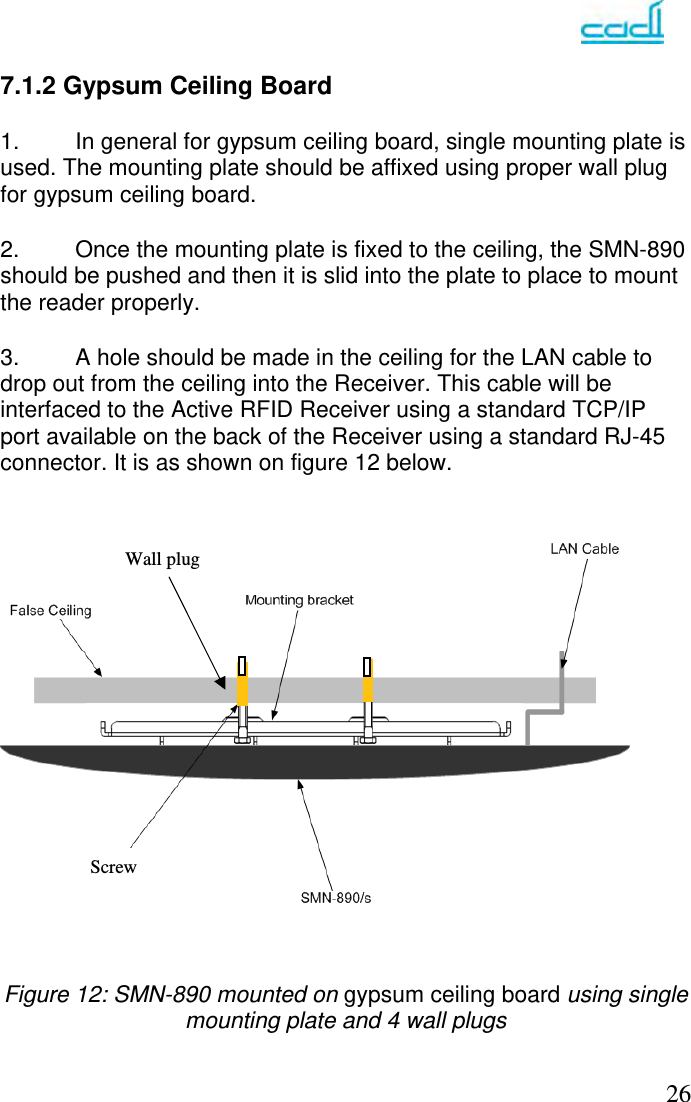
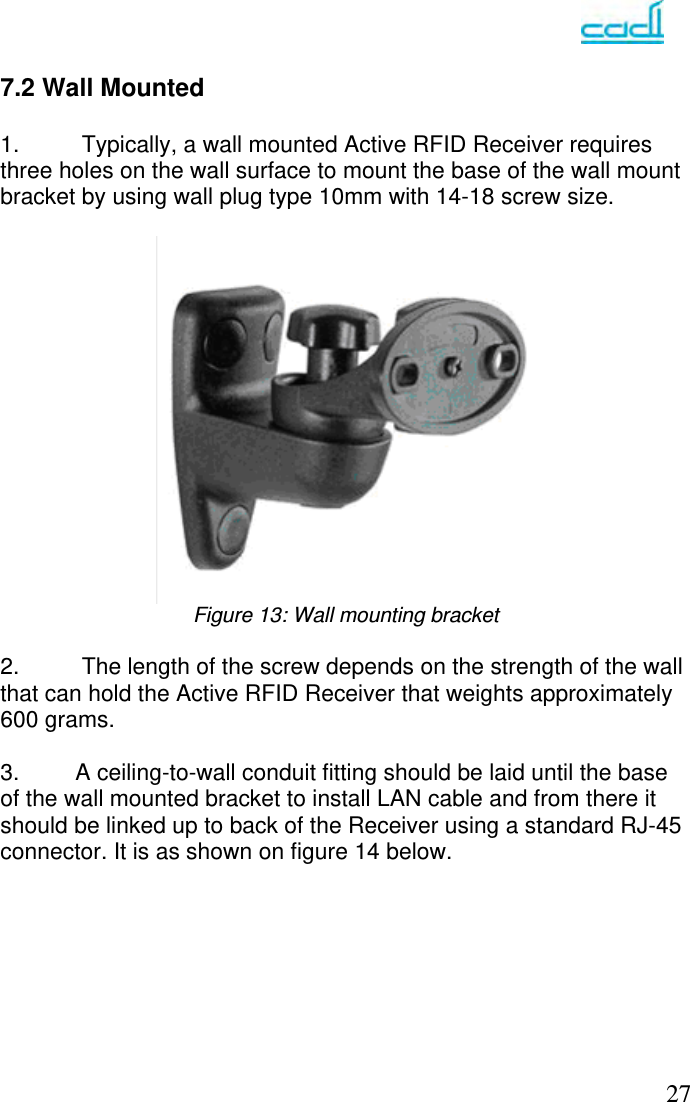
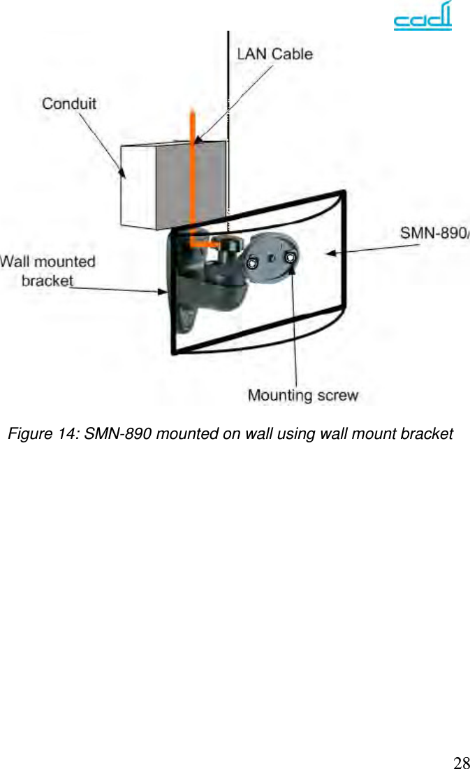
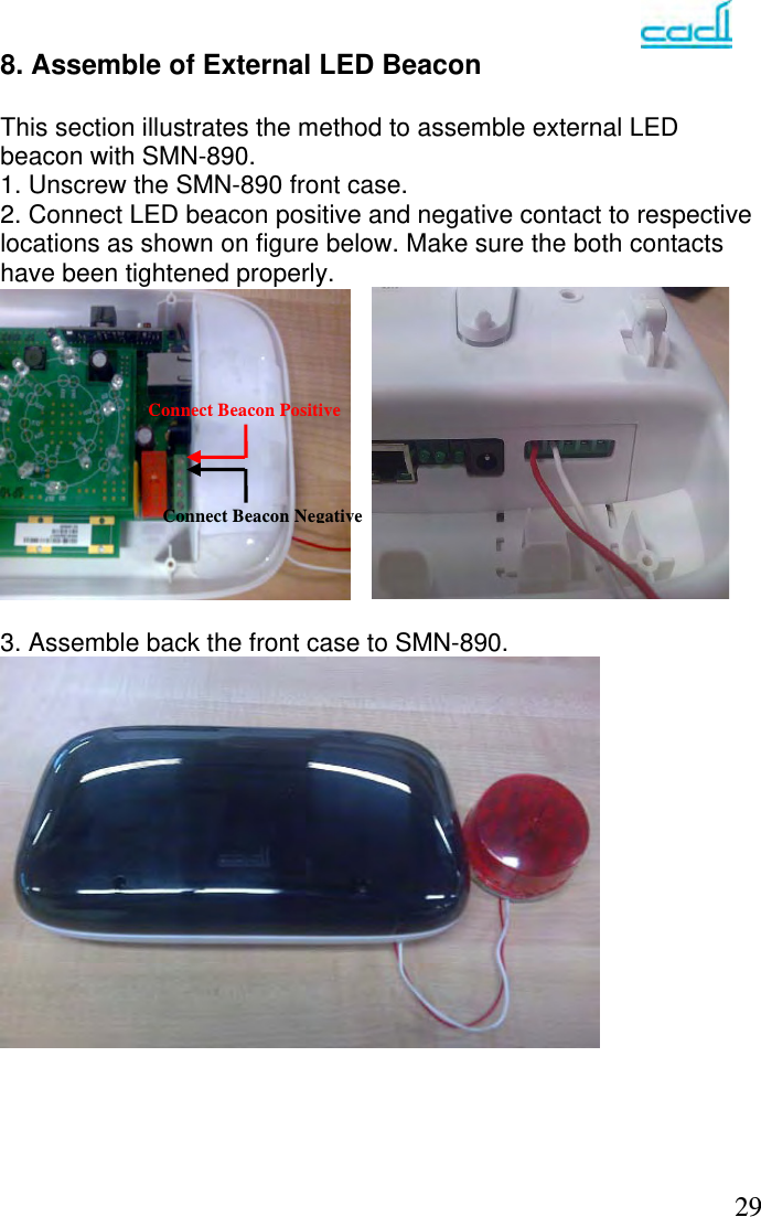
Cadi Scientific SMN890S SmartNode User Manual
Cadi Scientific Pte. Ltd. SmartNode
UserManual.wiki
>
Cadi Scientific
>
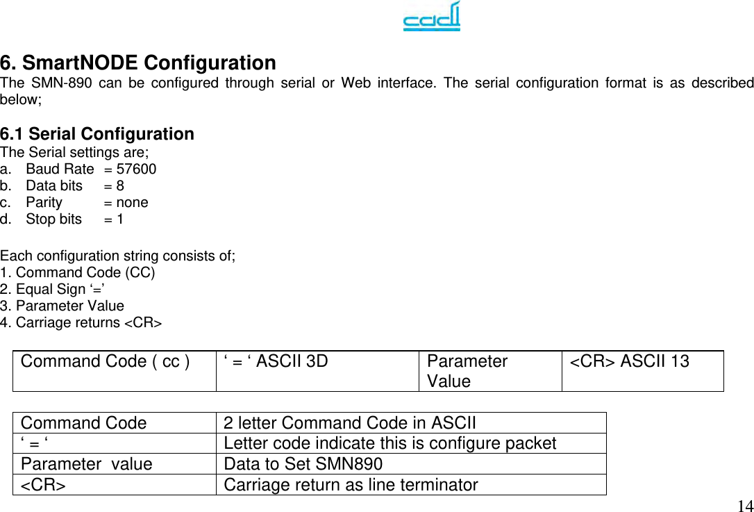
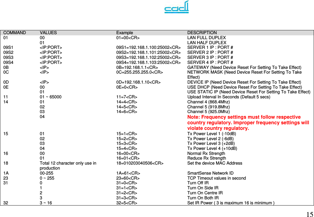
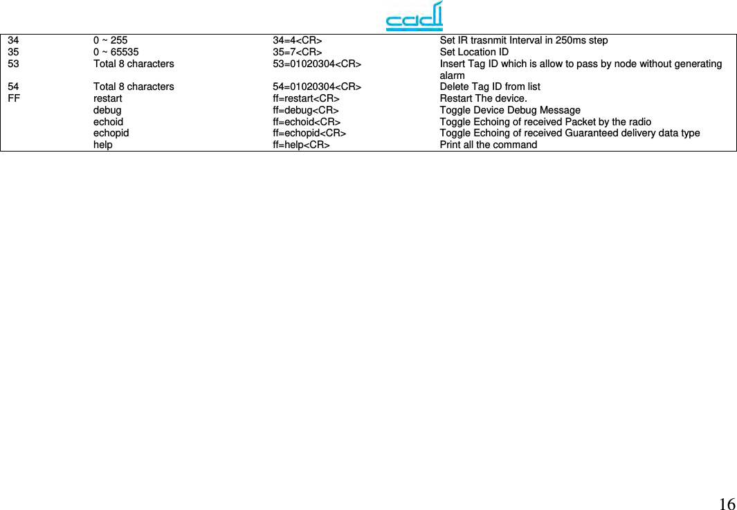
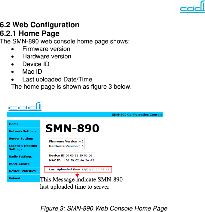
SMN890S User Manual
user manual
Navigation menu
Upload a User Manual
Namespaces
Wiki Guide
HTML
PDF
Info
Views
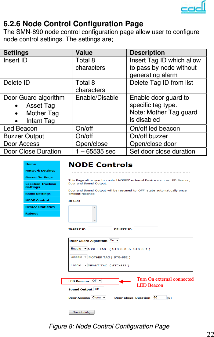
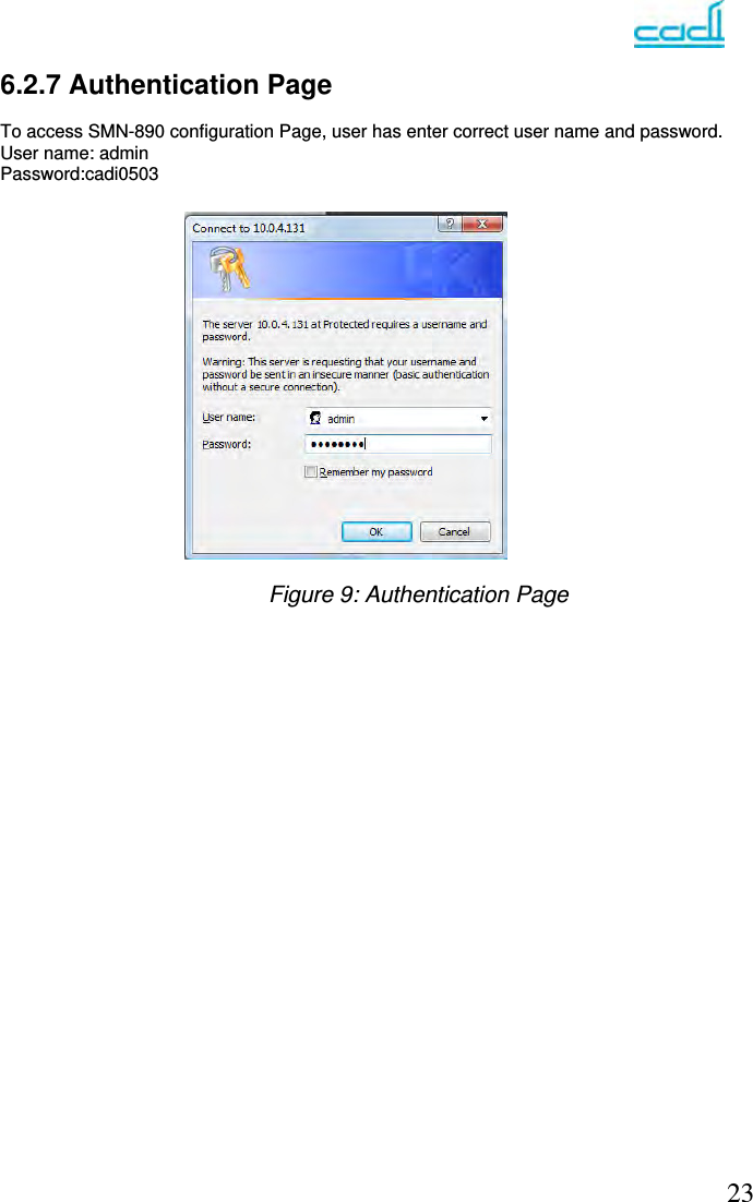
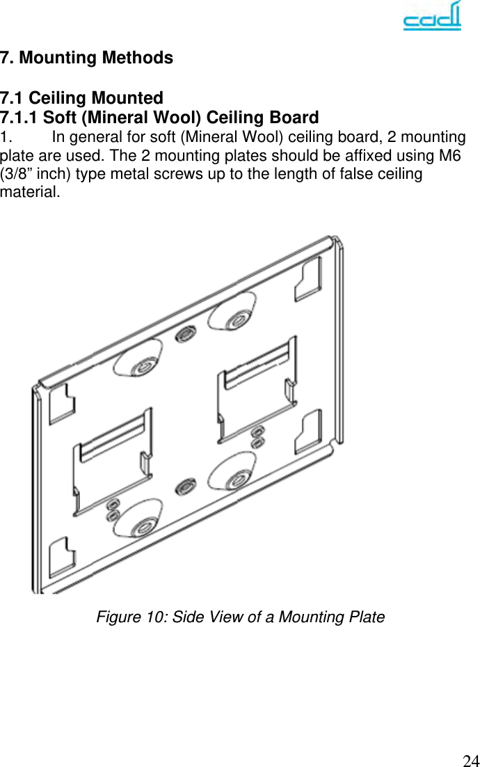
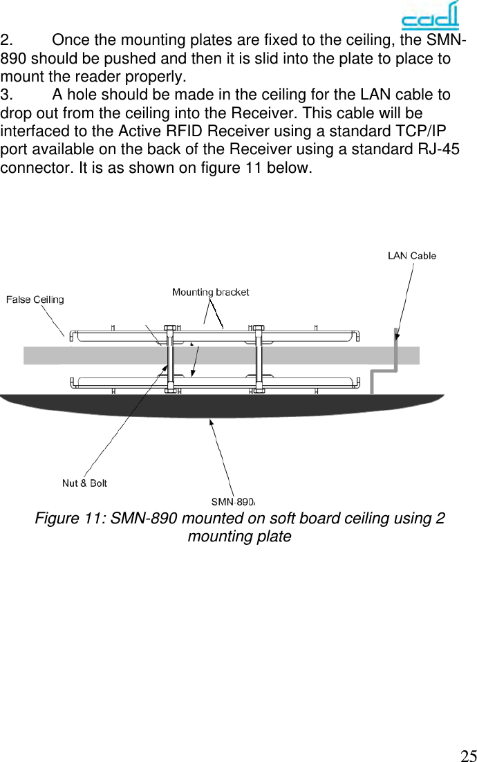
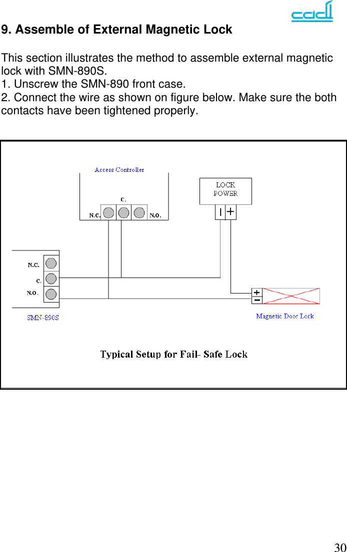
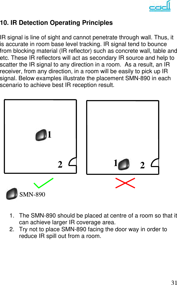
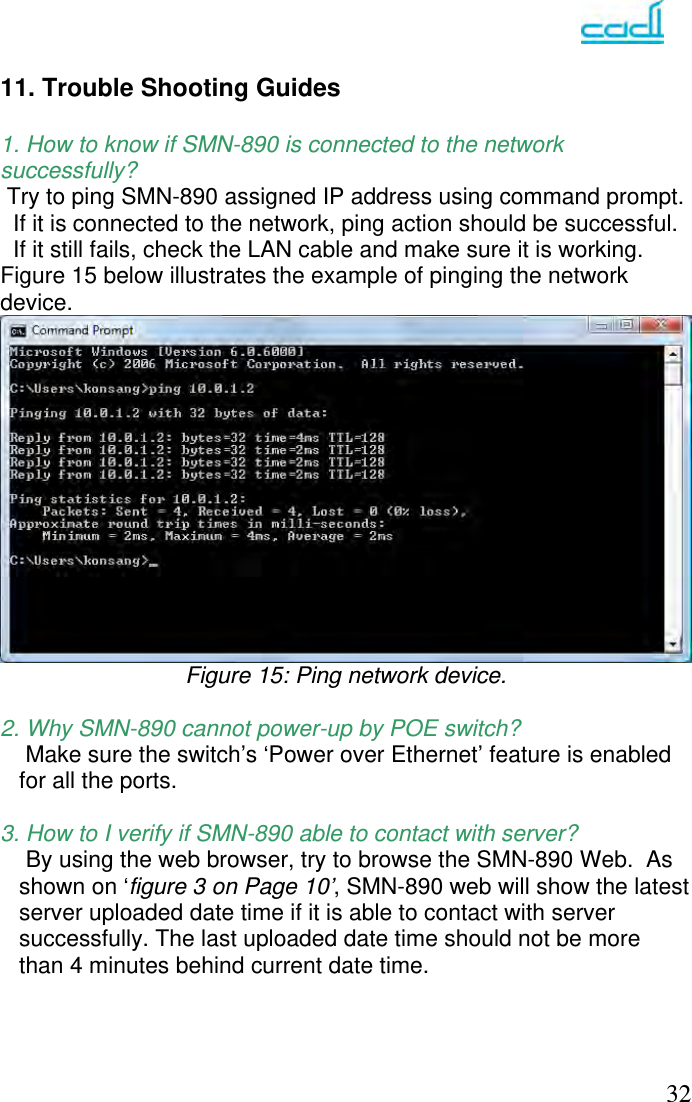
User Manual
Discussion / Help
Navigation