CPAC Systems CPAC1054 Charging Interface Control Unit User Manual InstallationInstructions
CPAC Systems AB Charging Interface Control Unit InstallationInstructions
Contents
- 1. UserManual_Safety
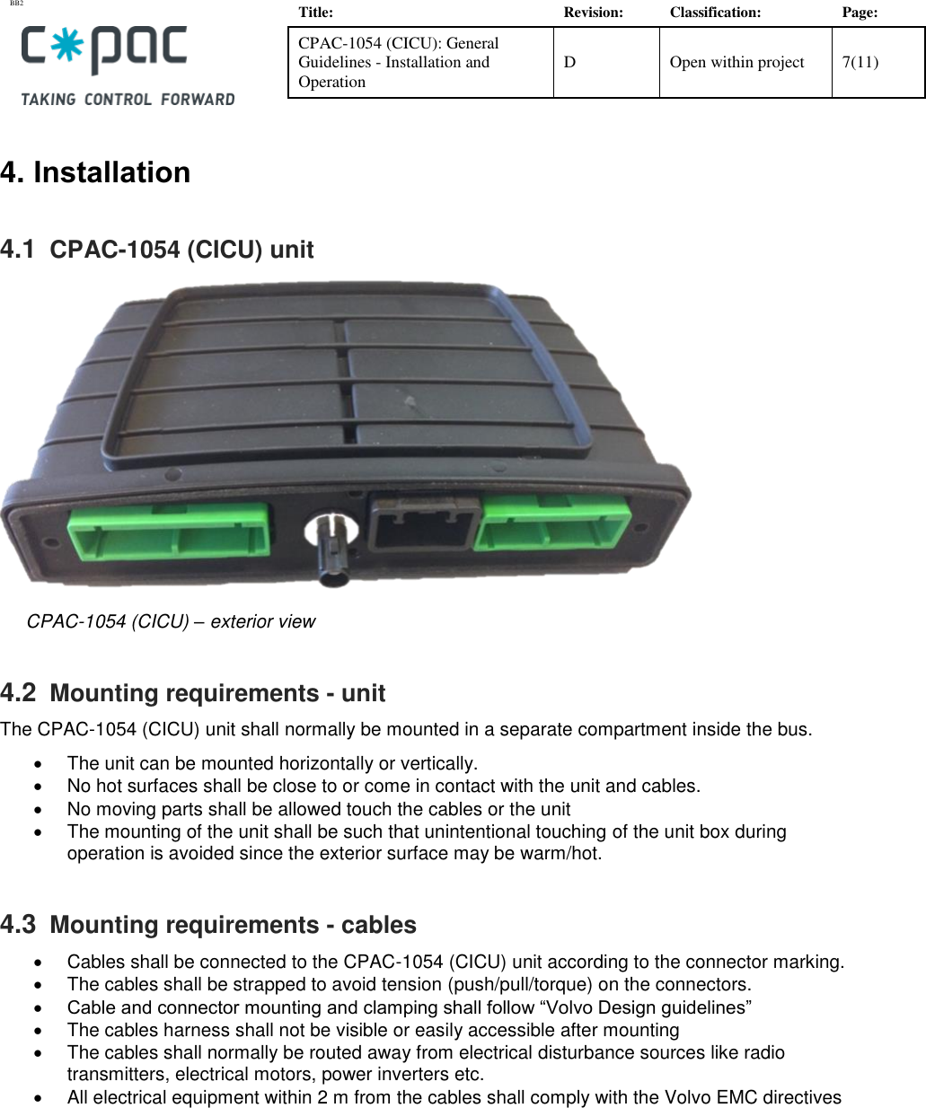
- 2. InstallationInstructions
- 3. Installation Instructions
- 4. Safety Precautions - Legal Statements
- 5. Declaration software security requirements
InstallationInstructions


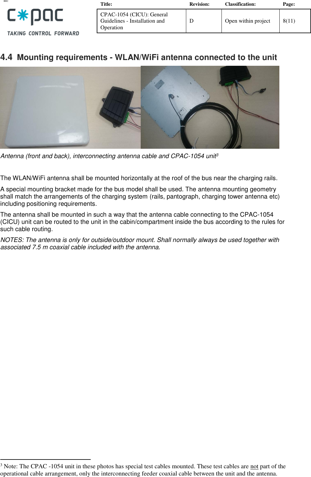
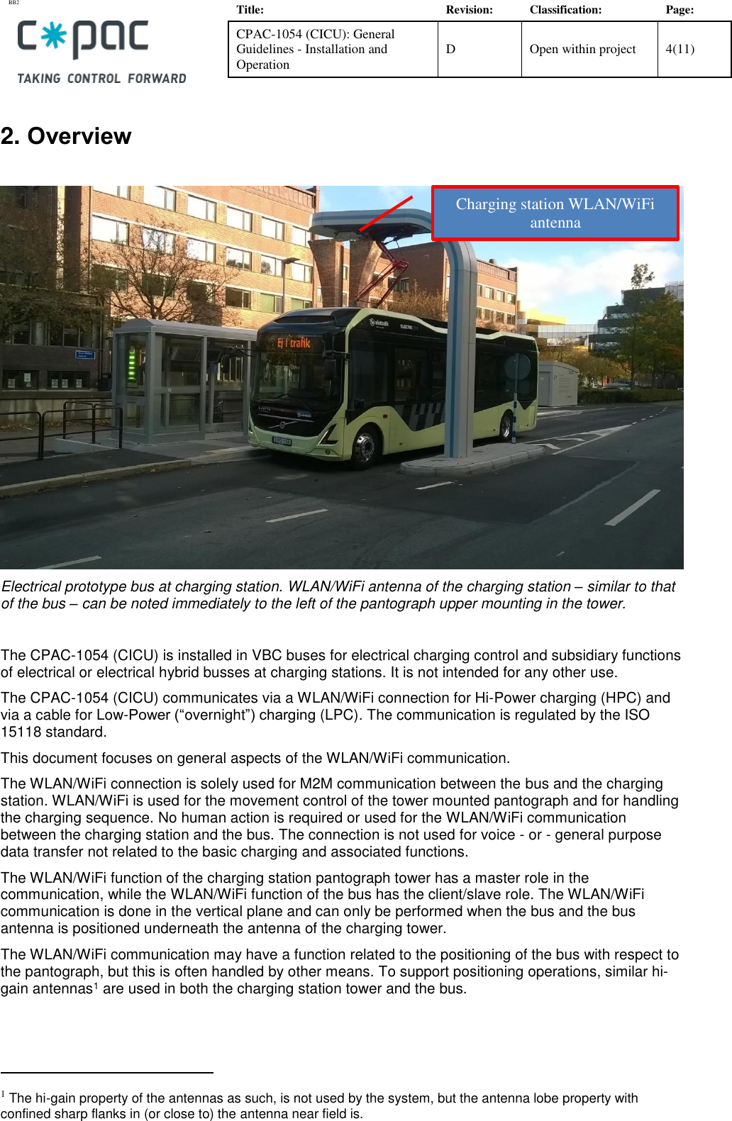
![BB2 Title: Revision: Classification: Page: CPAC-1054 (CICU): General Guidelines - Installation and Operation D Open within project 5(11) 3. Operation This section gives a description2 of the HPC (Hi Power Charging) sequence, focused on the use of the WLAN/WiFi, particularly the start-up sequence. Other portions have been deleted. 3.1 State Machine for HPC and initiation of communication WiFi SetupSECC Discovery[T2][T1]SECC Connection Establishment[T3]Wait for Parking Brake activationWait for System Conditions for Charging[T5]App Protocol Negotiation[T6]Session Setup[T7]Service DiscoveryService and Payment Selection[T8][T9]Contract Auth[T10]Charge Parameter DiscoveryCompatibilityCheck[T12]Cable Check[T13]Pre-charging[T14]Activate Charger ContactorsCharging[T15][T16][T317][T11][T108][T109][T110][T111][T112][T113][T214][T215][T106][T102]Exit function[T4][T103][T204][T205][T206][T107] [T207][T208][T209][T210][T211][T212][T213][T216]Session Termination AbnormalDeactivate Charger Contactors[T17][T19]Session Termination Normal[T219][T114][T115][T116]Charging Rampdown Abnormal[T217][T18][T321][T218][T120]HPC function inactiveHPC function active[T104] 2 The info is derived from a various specification document.](https://usermanual.wiki/CPAC-Systems/CPAC1054.InstallationInstructions/User-Guide-3339170-Page-5.png)


Installation Instructions
![BB2 Title: Revision: Classification: Page: CPAC-1054 (CICU): General Guidelines - Installation and Operation D Open within project 5(11) 3. Operation This section gives a description2 of the HPC (Hi Power Charging) sequence, focused on the use of the WLAN/WiFi, particularly the start-up sequence. Other portions have been deleted. 3.1 State Machine for HPC and initiation of communication WiFi SetupSECC Discovery[T2][T1]SECC Connection Establishment[T3]Wait for Parking Brake activationWait for System Conditions for Charging[T5]App Protocol Negotiation[T6]Session Setup[T7]Service DiscoveryService and Payment Selection[T8][T9]Contract Auth[T10]Charge Parameter DiscoveryCompatibilityCheck[T12]Cable Check[T13]Pre-charging[T14]Activate Charger ContactorsCharging[T15][T16][T317][T11][T108][T109][T110][T111][T112][T113][T214][T215][T106][T102]Exit function[T4][T103][T204][T205][T206][T107] [T207][T208][T209][T210][T211][T212][T213][T216]Session Termination AbnormalDeactivate Charger Contactors[T17][T19]Session Termination Normal[T219][T114][T115][T116]Charging Rampdown Abnormal[T217][T18][T321][T218][T120]HPC function inactiveHPC function active[T104] 2 The info is derived from a various specification document.](https://usermanual.wiki/CPAC-Systems/CPAC1054.Installation-Instructions/User-Guide-4041206-Page-5.png)