CANTOPS CTS-STBR-AA RFID Reader User Manual Appendix 8
CanTops RFID Reader Appendix 8
UserManual.wiki
>
CANTOPS
>
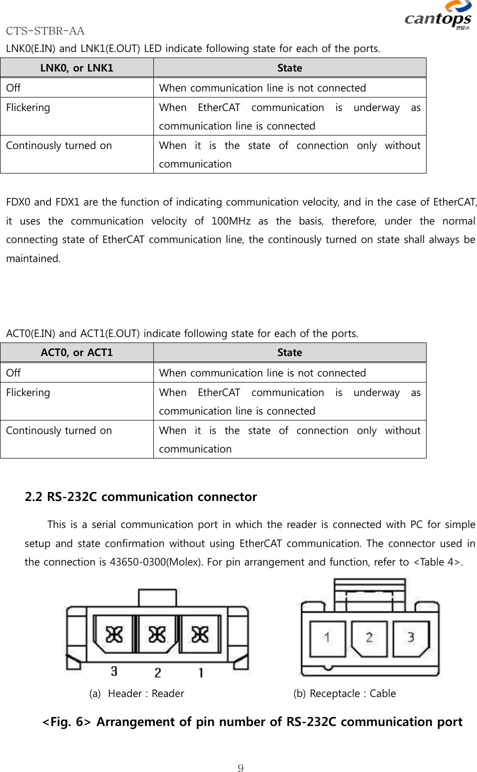
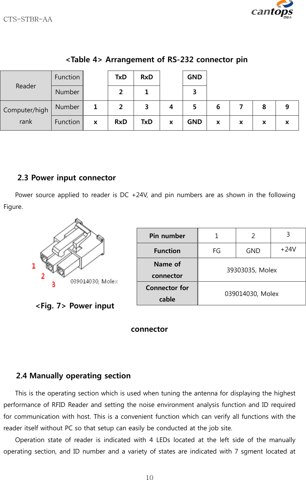
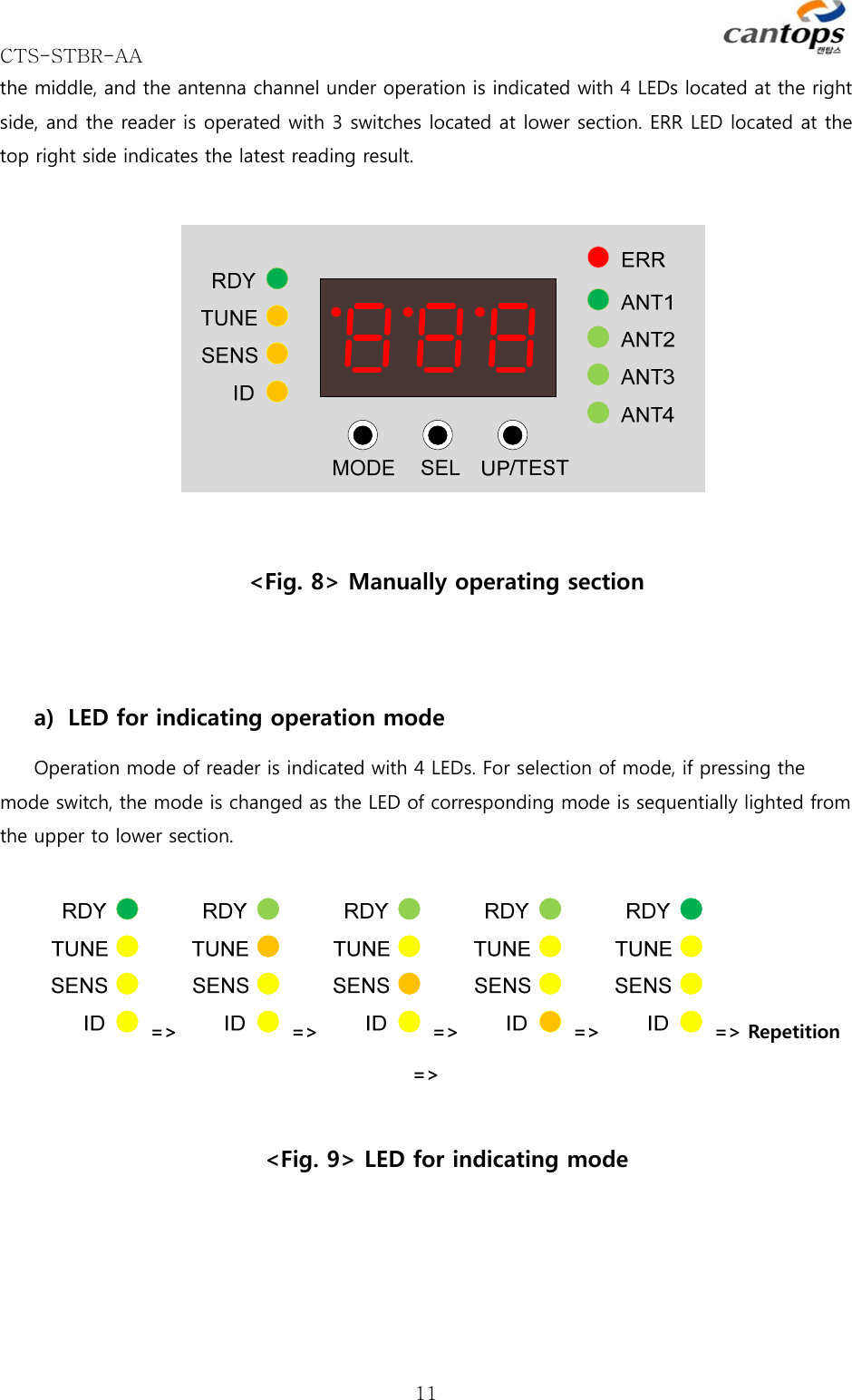
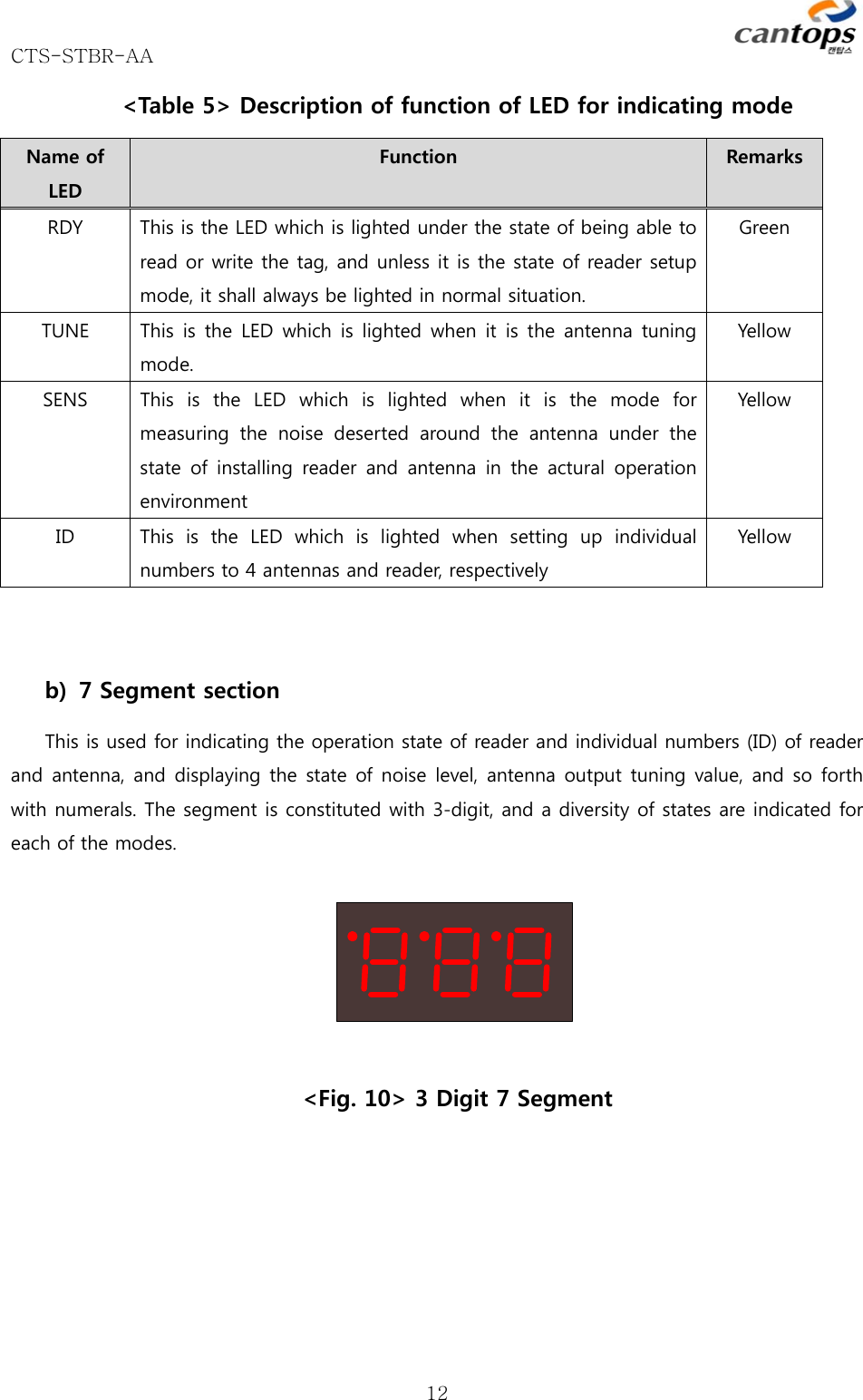
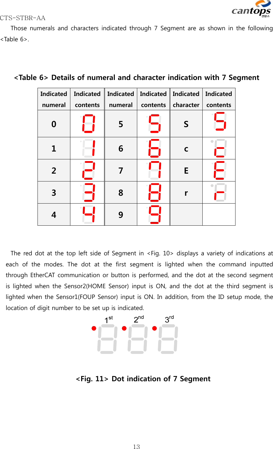
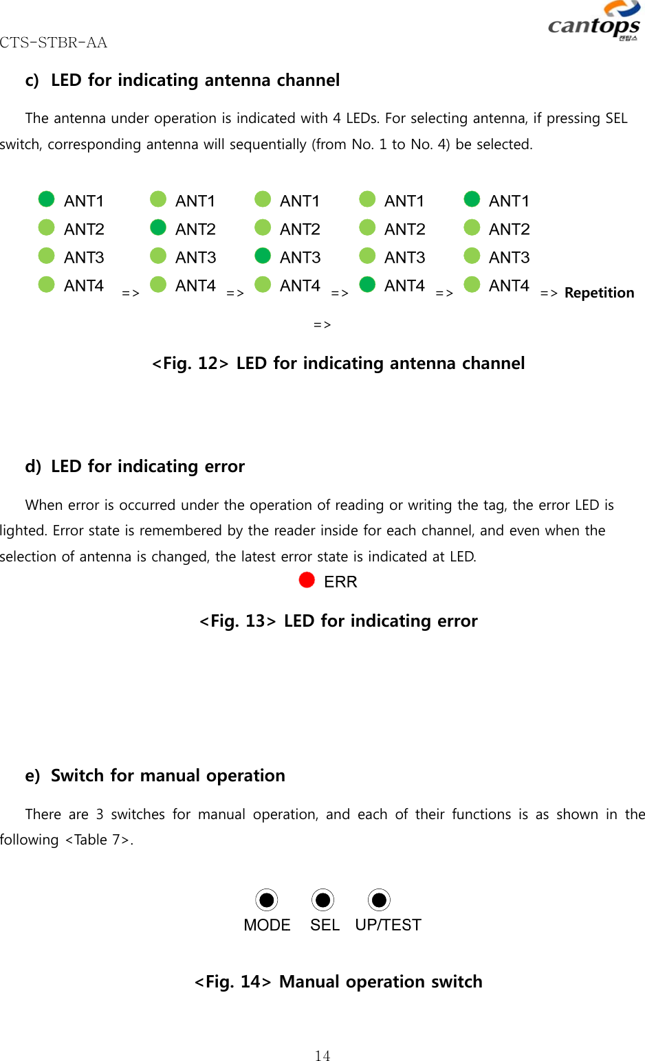
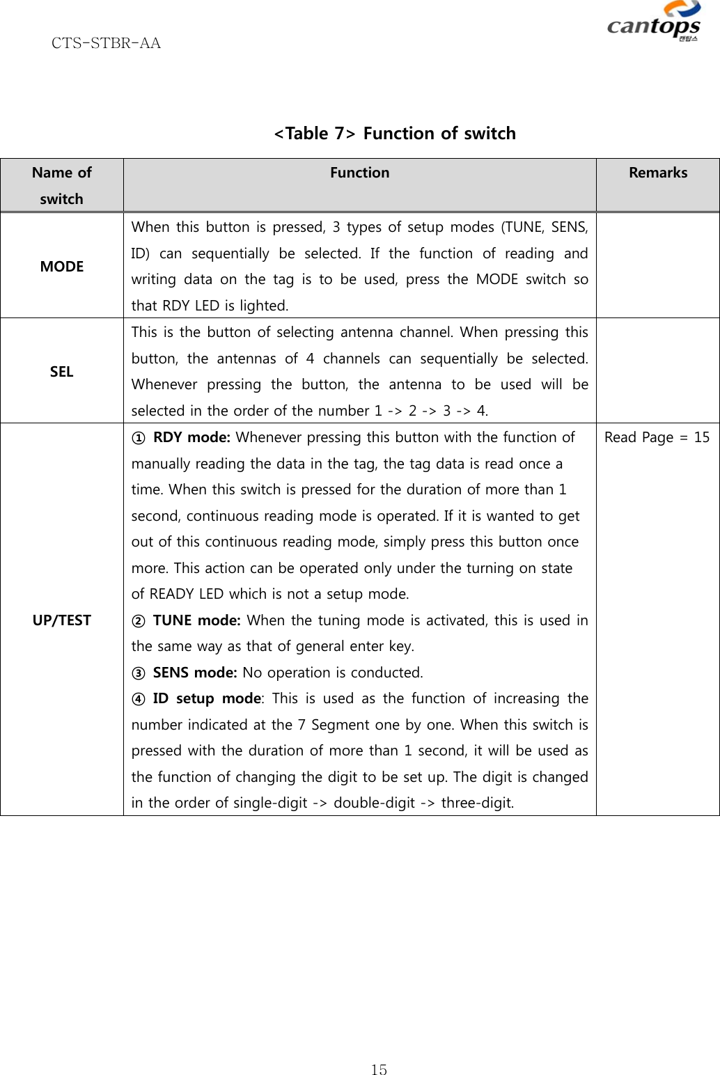
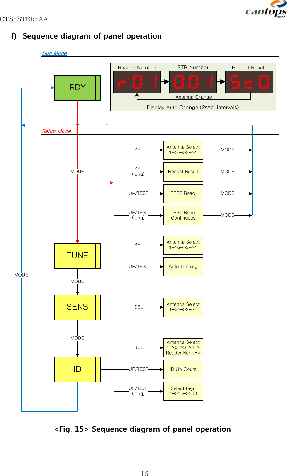
CTS STBR AA User Manual
Users Manual
Navigation menu
Upload a User Manual
Namespaces
Wiki Guide
HTML
PDF
Info
Views
User Manual
Discussion / Help
Navigation