CAEN RFID srl CAENRFID010 Low Power OEM UHF Compact RFID Reader User Manual RFIDdemo
CAEN RFID srl Low Power OEM UHF Compact RFID Reader RFIDdemo
Contents
- 1. Users Manual I
- 2. Users Manual II
- 3. Users Manual III
- 4. Users Manual IV
- 5. User Manual
Users Manual IV
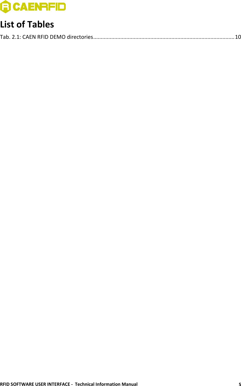

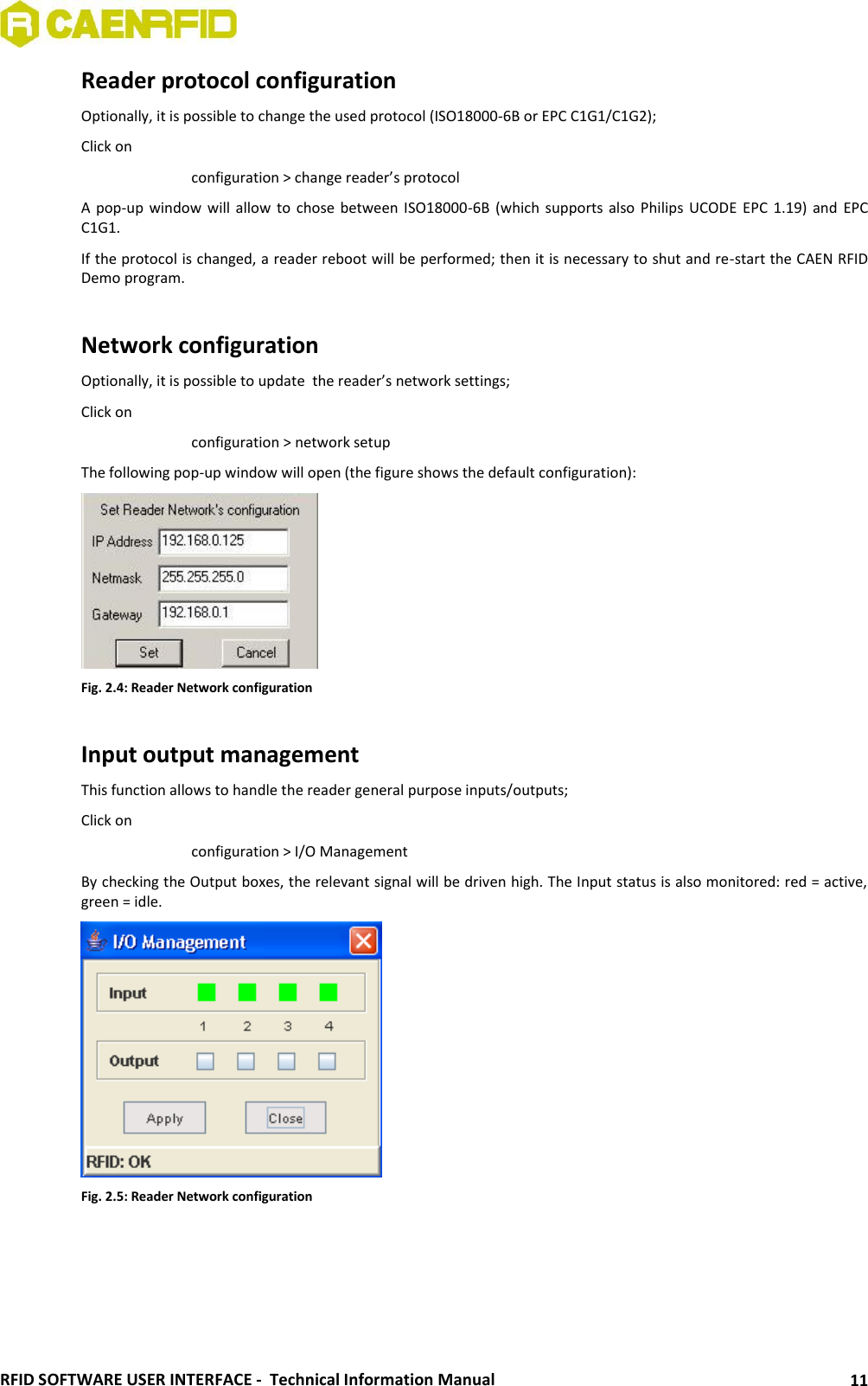
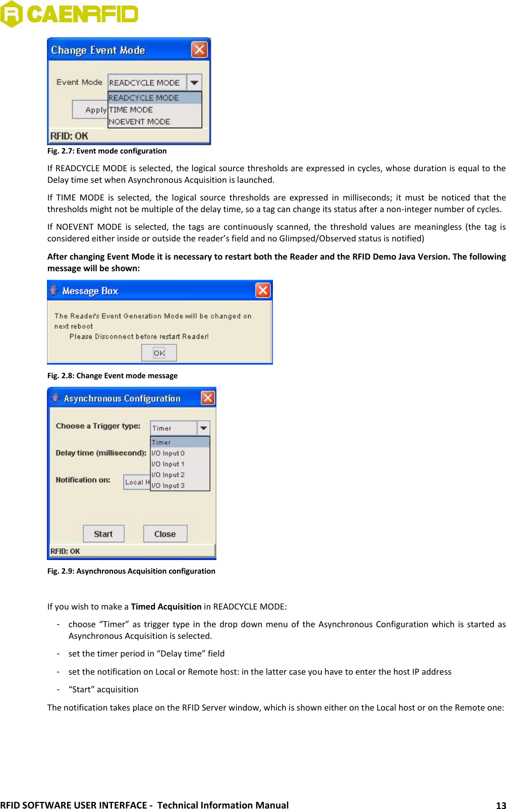
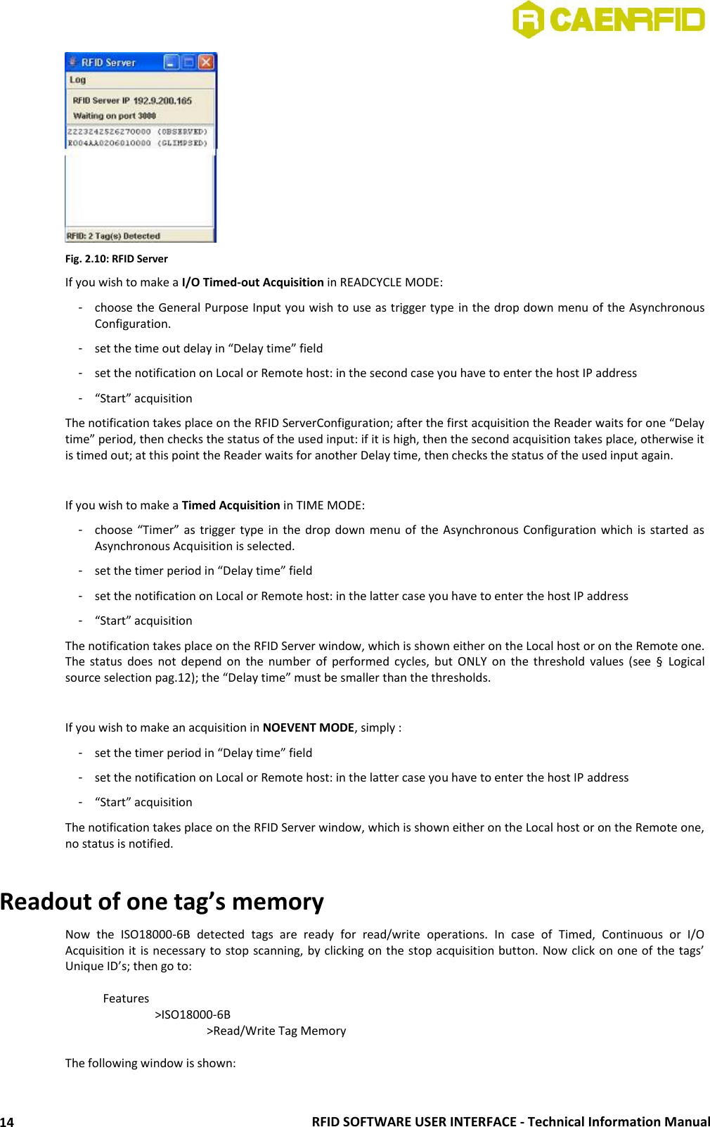
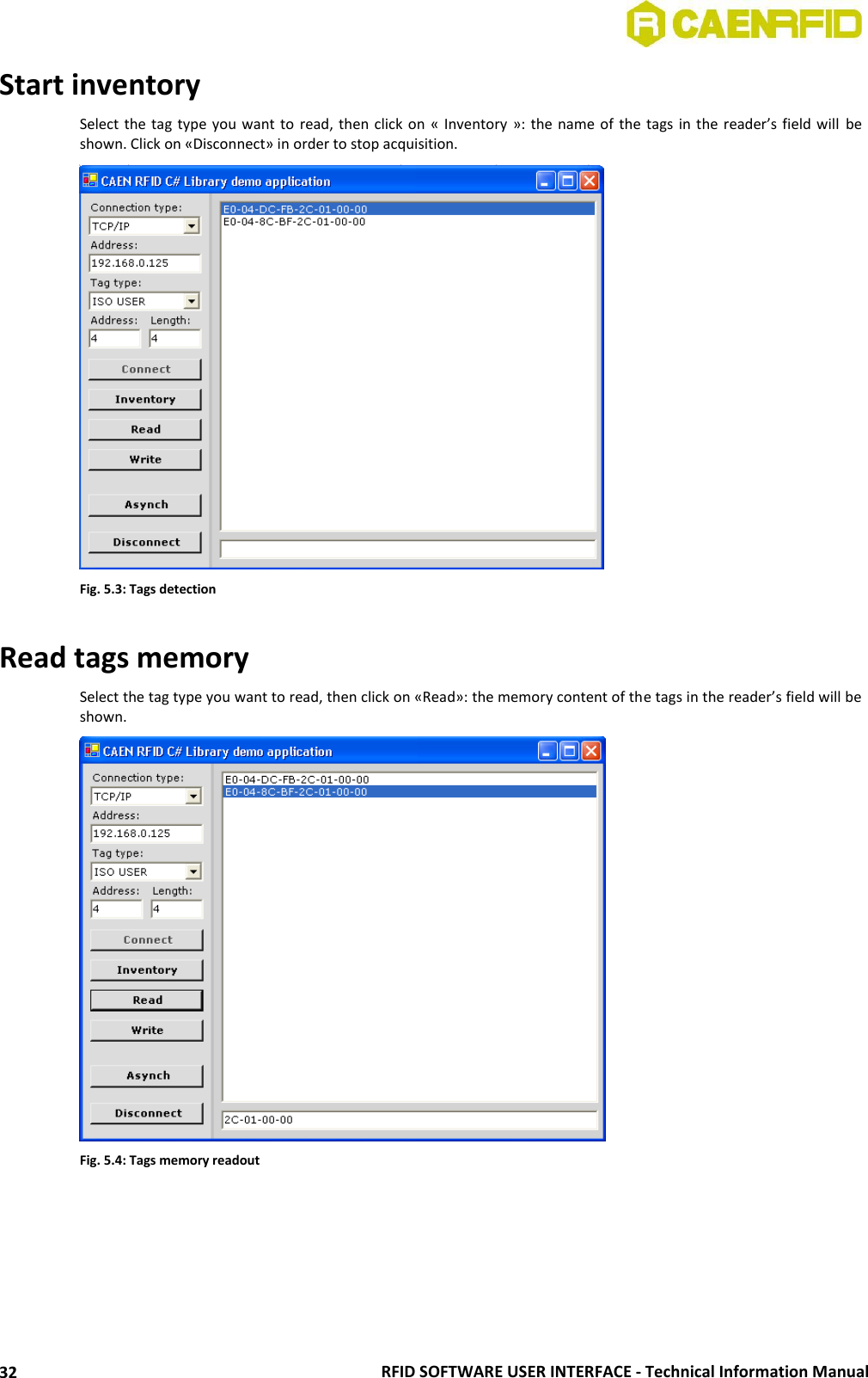
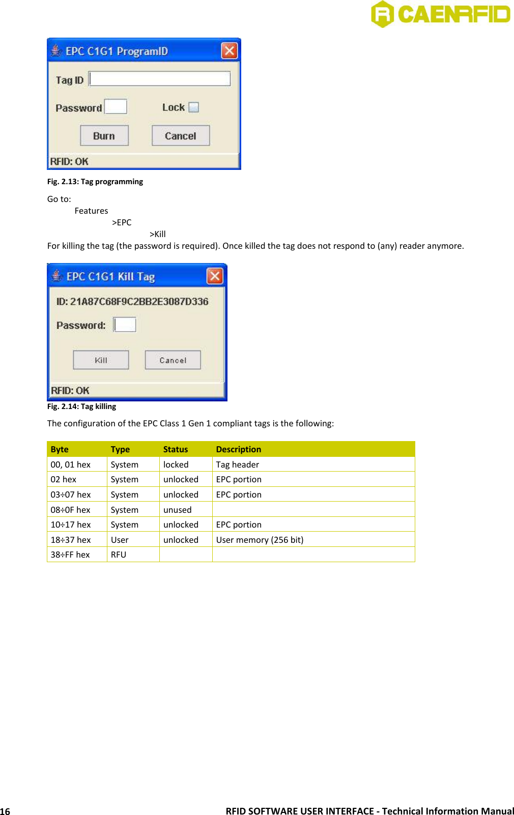
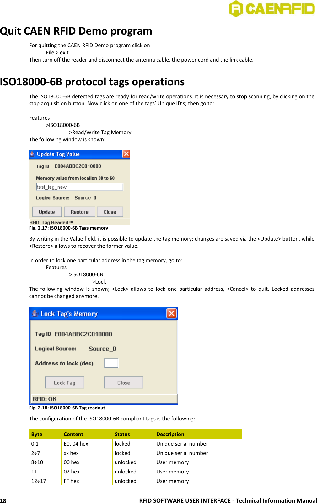
![RFID SOFTWARE USER INTERFACE - Technical Information Manual 15 Fig. 2.11: Tags memory By writing in the Value field, it is possible to update the tag memory; changes are saved via the <Update> button, while <Restore> allows to recover the former value. In order to lock one particular address in the tag memory, go to: Features >ISO18000-6B >Lock The following window is shown; <Lock> allows to lock one particular address, <Cancel> to quit. Locked addresses cannot be changed anymore. Fig. 2.12: Tag readout The configuration of the ISO18000-6B compliant tags is the following: Byte Content Status Description 0,1 E0, 04 hex locked Unique serial number 2÷7 xx hex locked Unique serial number 8÷10 00 hex unlocked User memory 11 02 hex unlocked User memory 12÷17 FF hex unlocked User memory 18÷219 00 hex unlocked User memory 220÷223 57 5F 4F 4B hex unlocked “w_ok” in ASCII, user memory The CAEN RFID Demo program allows to write only bits [2; 17]. EPC protocol tags operations If EPC tags are detcted, then go to: Features >EPC >Program ID For (over)writing the tags ID, setting the password, and locking them:](https://usermanual.wiki/CAEN-RFID-srl/CAENRFID010.Users-Manual-IV/User-Guide-1405619-Page-15.png)
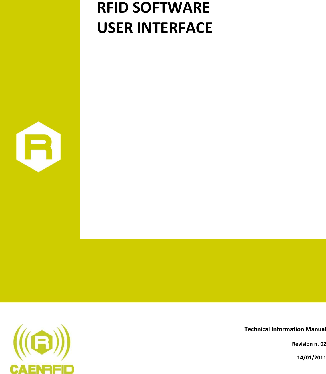
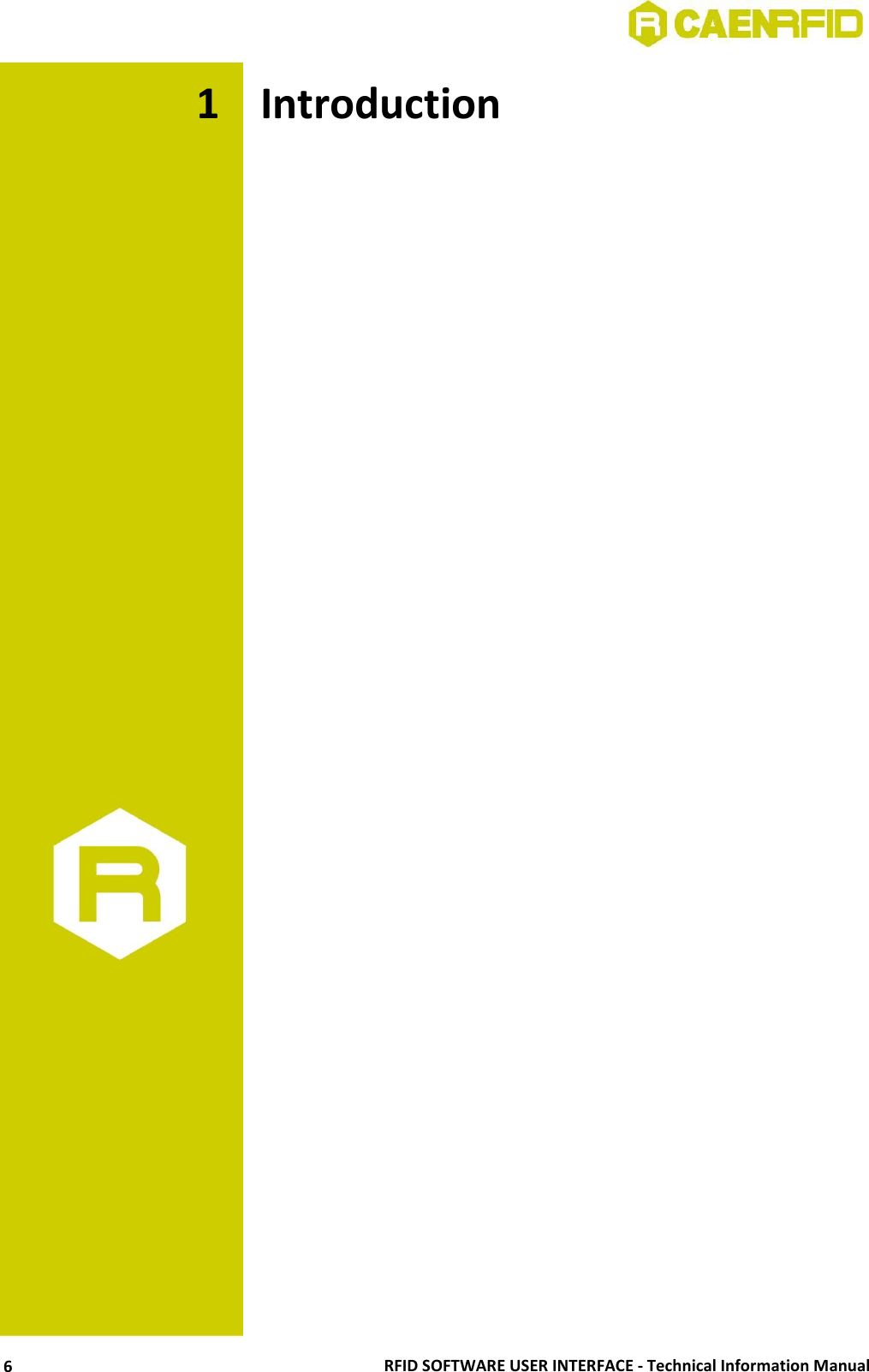
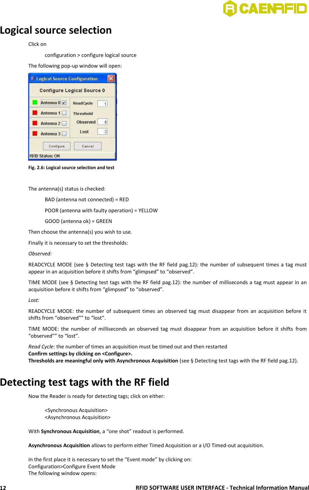
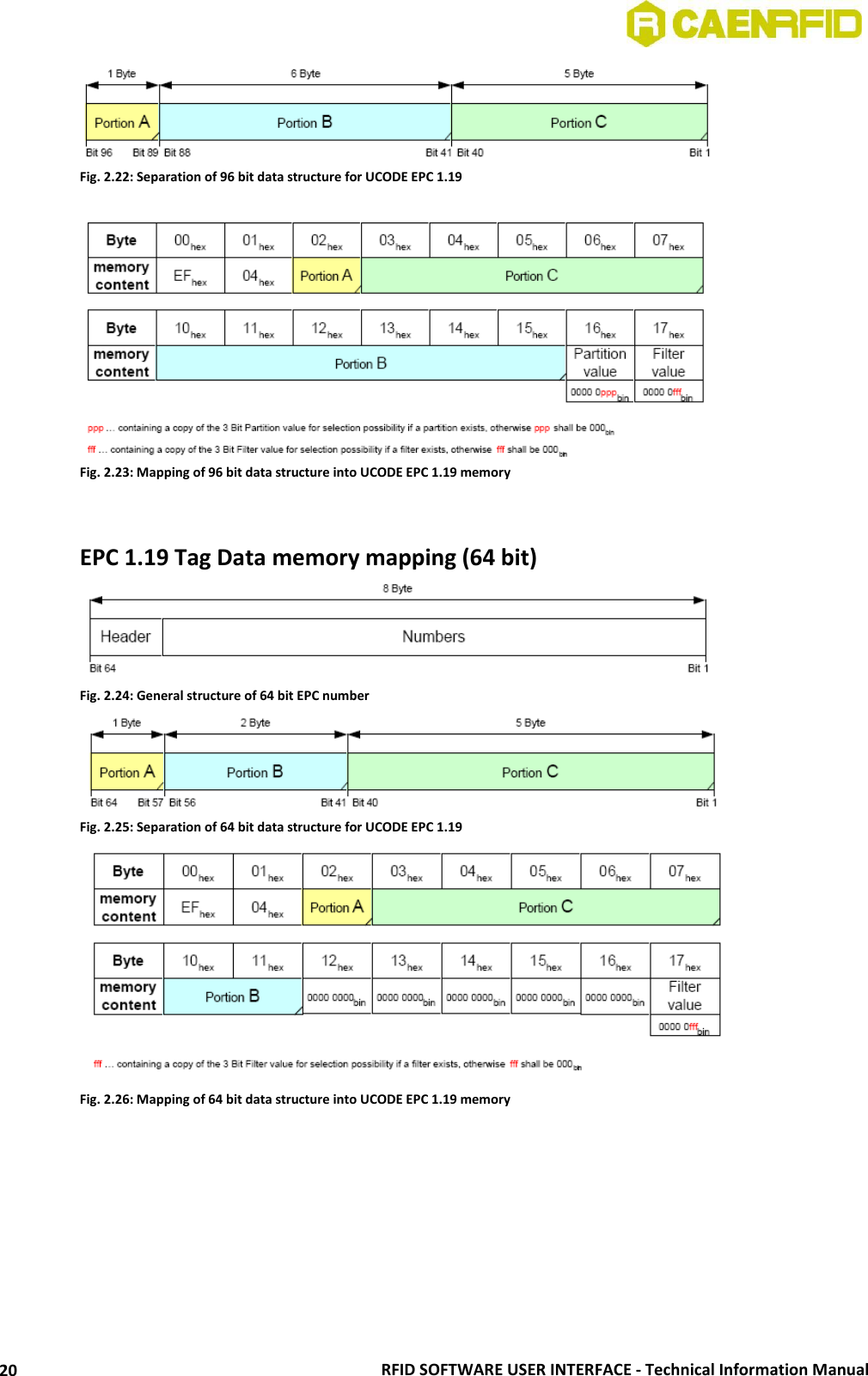
![RFID SOFTWARE USER INTERFACE - Technical Information Manual 19 18÷219 00 hex unlocked User memory 220÷223 57 5F 4F 4B hex unlocked “w_ok” in ASCII, user memory The CAEN RFID Demo program allows to write only bits [2; 17]. EPC1.19 protocol tags operations If EPC1.19 tags are detected, then go to: Features >EPC1.19 > Read/Write Tag Memory For (over)writing the tags ID and Memory: Fig. 2.19: EPC1.19 Tag programming In order to lock one particular address in the tag memory, go to Go to: Features >EPC1.19 >Lock The following window is shown; <Lock> allows to lock one particular address, <Cancel> to quit. Locked addresses cannot be changed anymore. Fig. 2.20: EPC1.19 Tag locking EPC 1.19 Tag Data memory mapping (96 bit) Fig. 2.21: General structure of 96 bit EPC number](https://usermanual.wiki/CAEN-RFID-srl/CAENRFID010.Users-Manual-IV/User-Guide-1405619-Page-19.png)
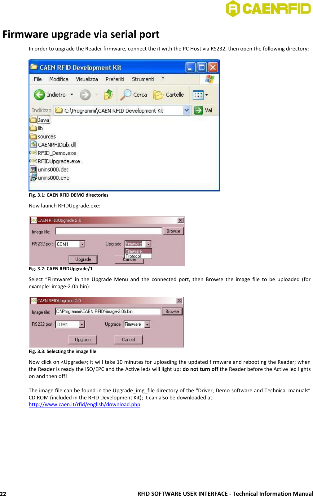
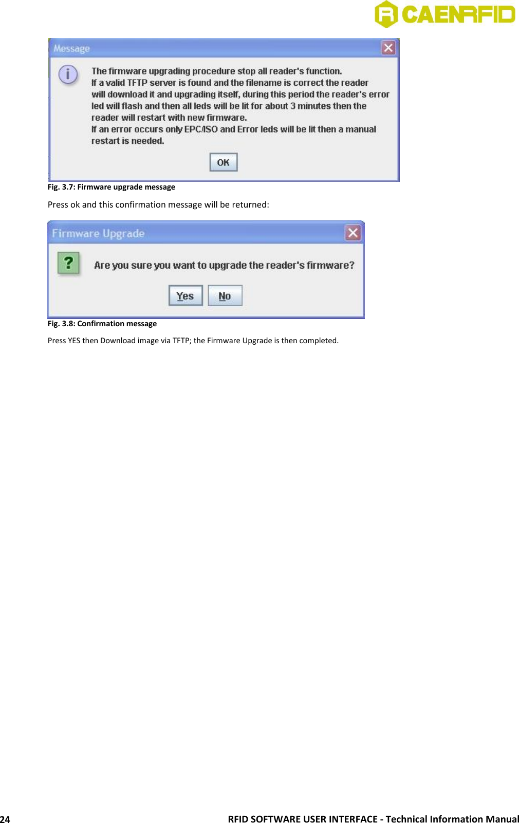
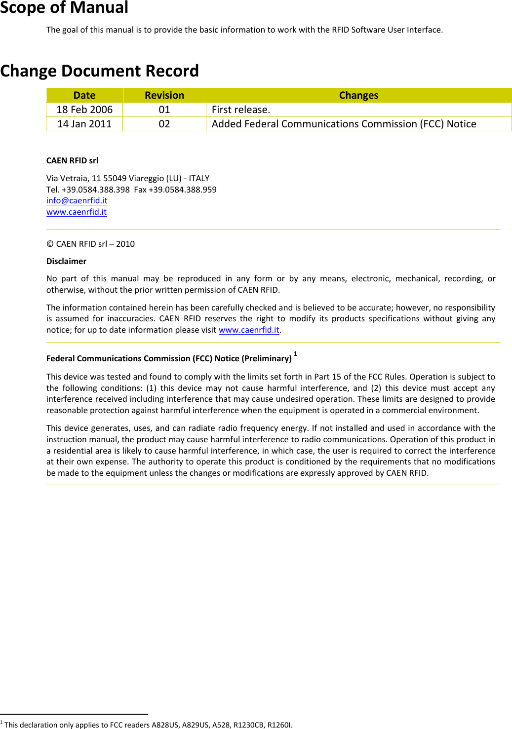
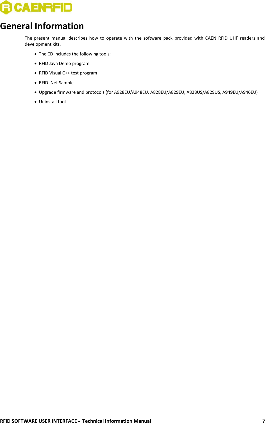
![RFID SOFTWARE USER INTERFACE - Technical Information Manual 23 Firmware upgrade via TCP/IP The Firmware upgrade via TCP/IP works only with the CAENRFID Demo Java Version. First you need a TFTP Server & Client application, if you have not one installed, you can download (from http://www.klever.net/), install and run the pumpkin.exe freeware application: Fig. 3.4: PumpKIN Menu Window Select [Options] and browse the folder where the image file resides with the following selections, then press [OK] Fig. 3.5: PumpKIN Options Window Connect to the Reader by using CAEN RFID Demo Java version and select Configuration>Firmware Upgrade enter the TFTP server address and browse the image file to be loaded into the Reader, then press [OK]: Fig. 3.6: Firmware upgrade browser The following information message will then be shown:](https://usermanual.wiki/CAEN-RFID-srl/CAENRFID010.Users-Manual-IV/User-Guide-1405619-Page-23.png)