CAEN RFID srl CAENRFID003 A528 - OEM UHF multiregional Compact Reader User Manual Mod A528 OEM UHF Multiregional compact reader
CAEN RFID srl A528 - OEM UHF multiregional Compact Reader Mod A528 OEM UHF Multiregional compact reader
Contents
- 1. User Manual 1
- 2. User Manual 2
- 3. User Manual 3
- 4. User Manual 4
User Manual 1
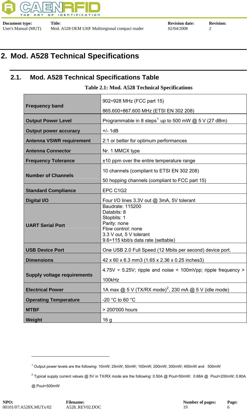
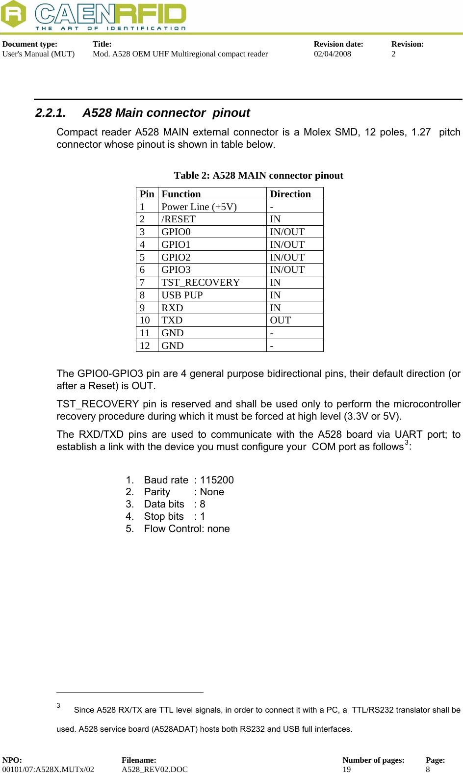
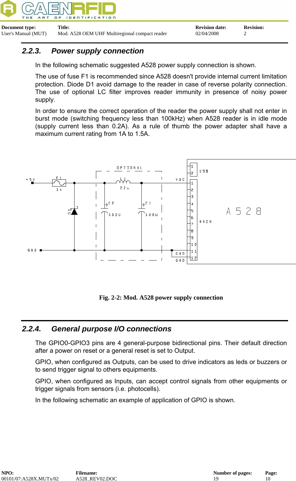
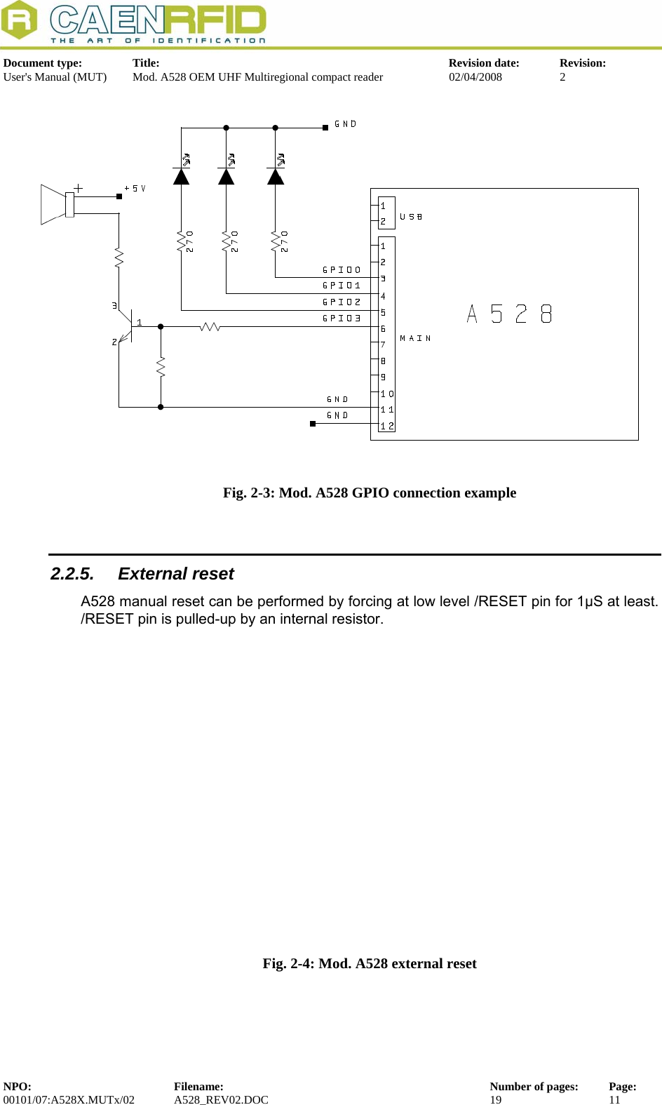
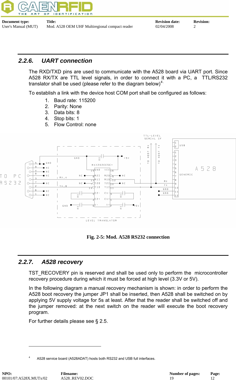
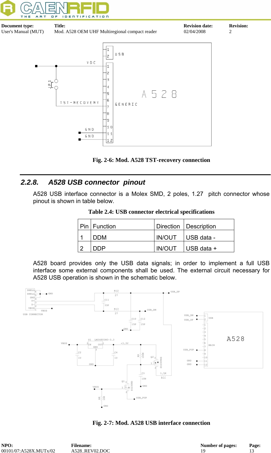
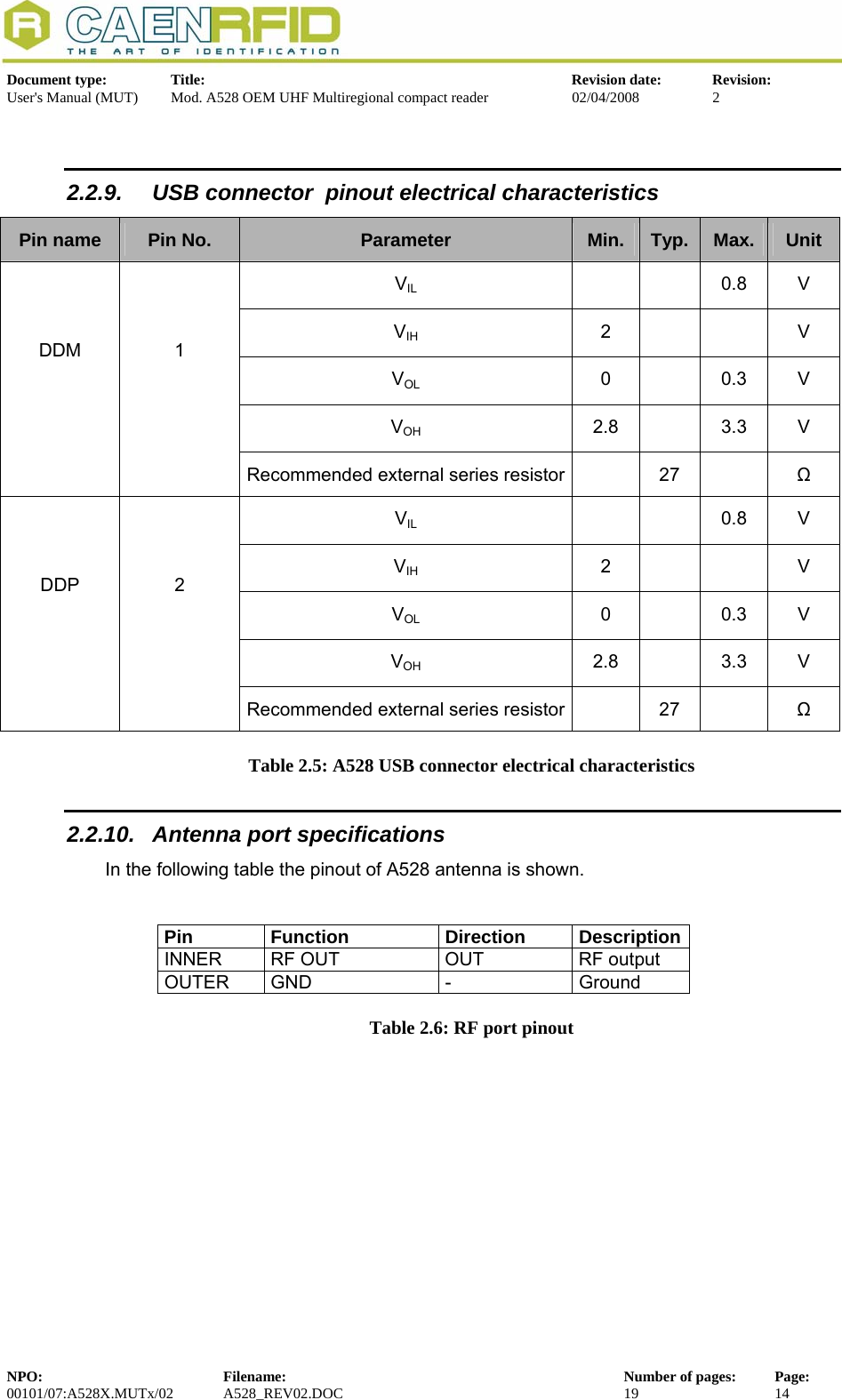
![Document type: Title: Revision date: Revision: User's Manual (MUT) Mod. A528 OEM UHF Multiregional compact reader 02/04/2008 2 2.2.2. A528 MAIN connector electrical characteristics Table 2.3: A528 main connector electrical characteristics Pin name Pin No. Parameter Min. Typ. Max. Unit Supply DC voltage 4.75 5.00 5.25 V Power supply requirements – Ripple Voltage 100 mVpp Power supply requirements - Ripple Frequency 100 kHz +5V 1 Supply DC current 0.23 1.0 A VIL -0.3 1.0 V VIH 2.4 3.6 V Internal pull-up resistance 10 20 kΩ /RESET 2 Pulse width 1 μs VOL 0 0.4 V VOH 2.0 3.3 V Output current 3.0 mA VIL -0.3 0.8 V VIH 2.0 5.5 V GPIO[0:3] 3, 4, 5, 6 Input current 1 μA TST-Recovery 7 VIH 2.0 5.5 V USB PUP 8 VIH 2.0 5.5 V VIL -0.3 0.8 V VIH 2.0 5.5 V RXD 9 Input current 1 μA VOL 0 0.4 V VOH 2.4 3.3 V TXD 10 Output current 1.5 mA GND 11,12 NPO: Filename: Number of pages: Page: 00101/07:A528X.MUTx/02 A528_REV02.DOC 19 9](https://usermanual.wiki/CAEN-RFID-srl/CAENRFID003.User-Manual-1/User-Guide-959661-Page-9.png)