Brooks Automation UF70 RFID UHF Reader User Manual Product Manual
Brooks Automation (Germany) GmbH RFID Division RFID UHF Reader Product Manual
UserManual.wiki
>
Brooks Automation
>
UF70 User Manual
>
User Manual
Contents
1.
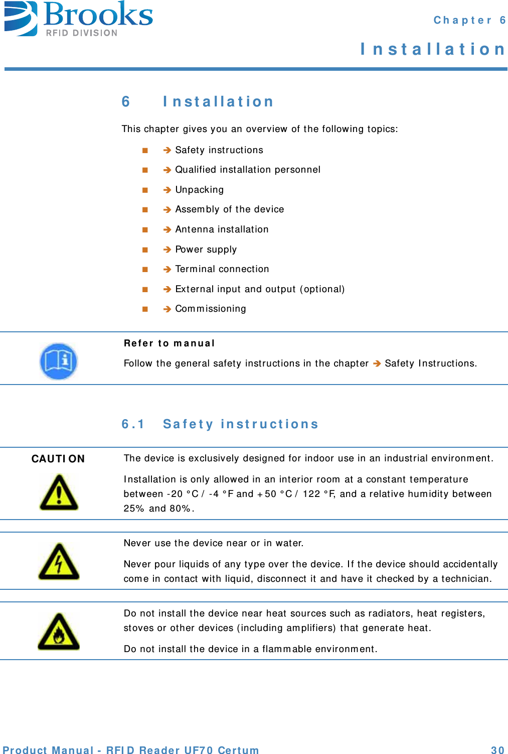
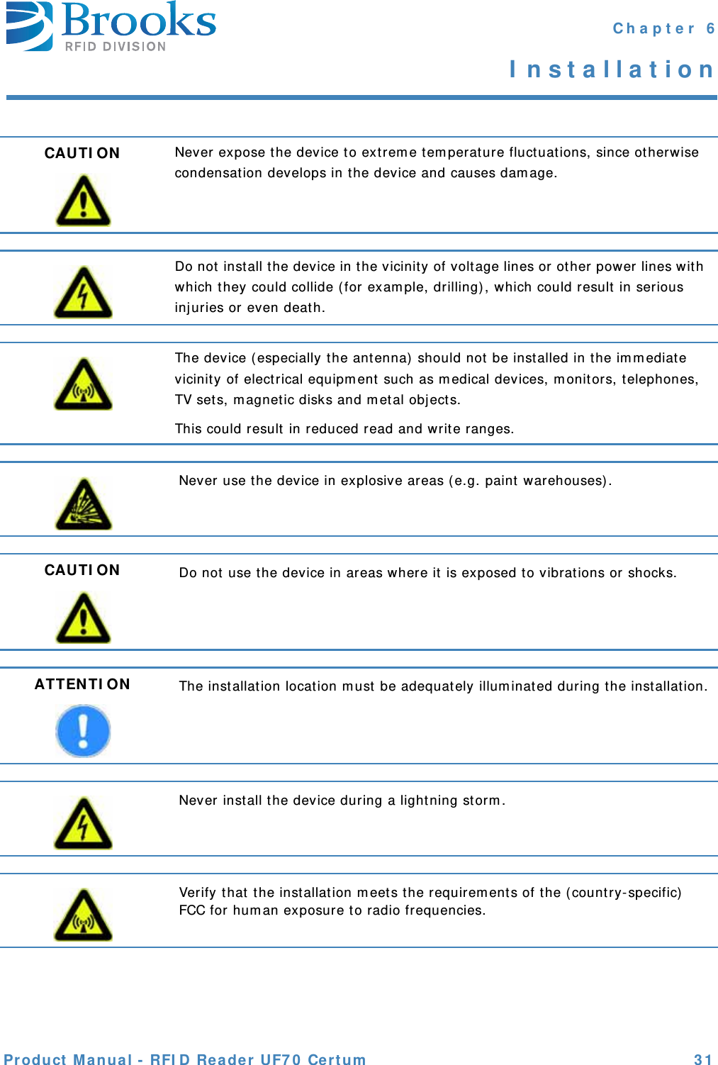
Installation Guide
2.
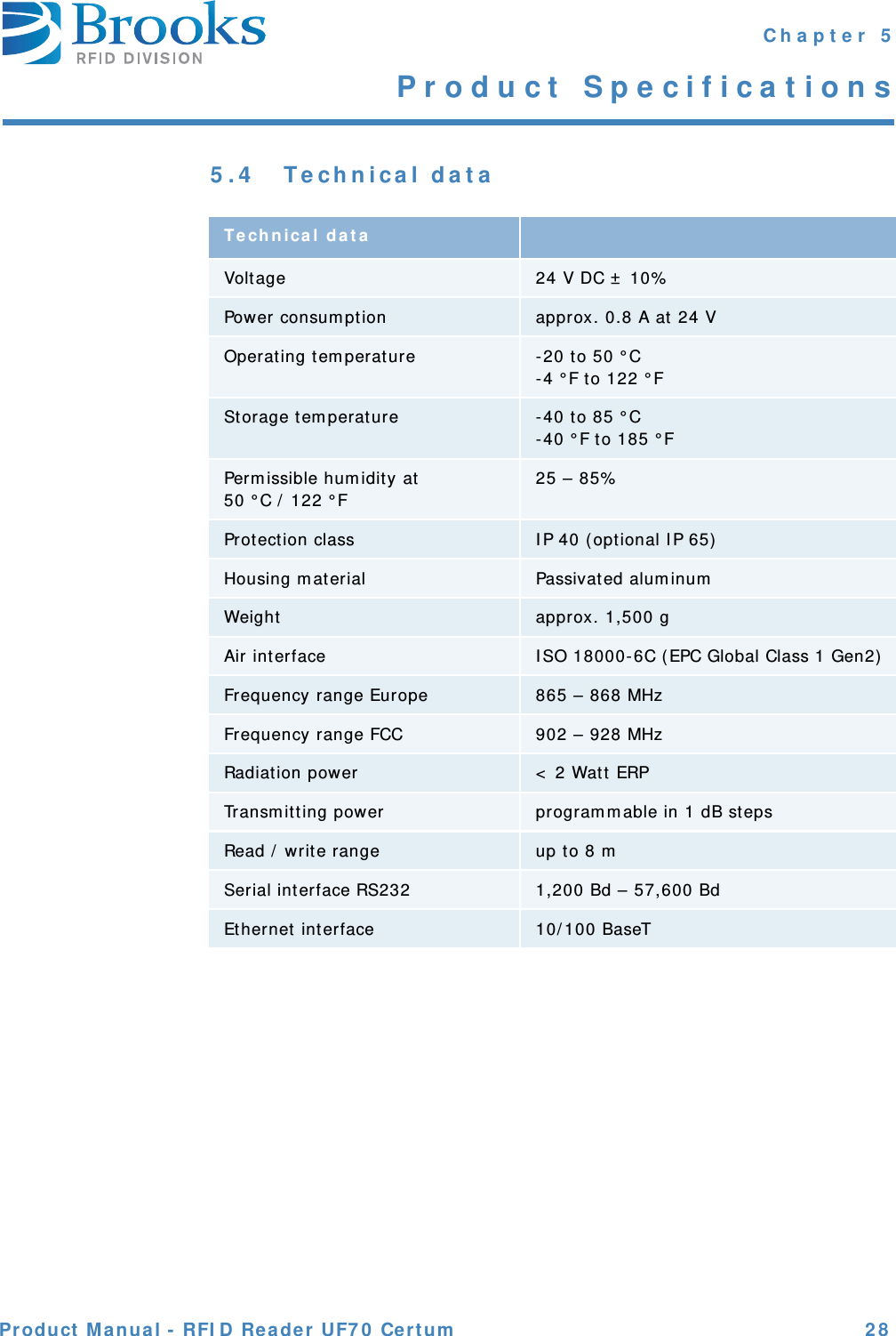
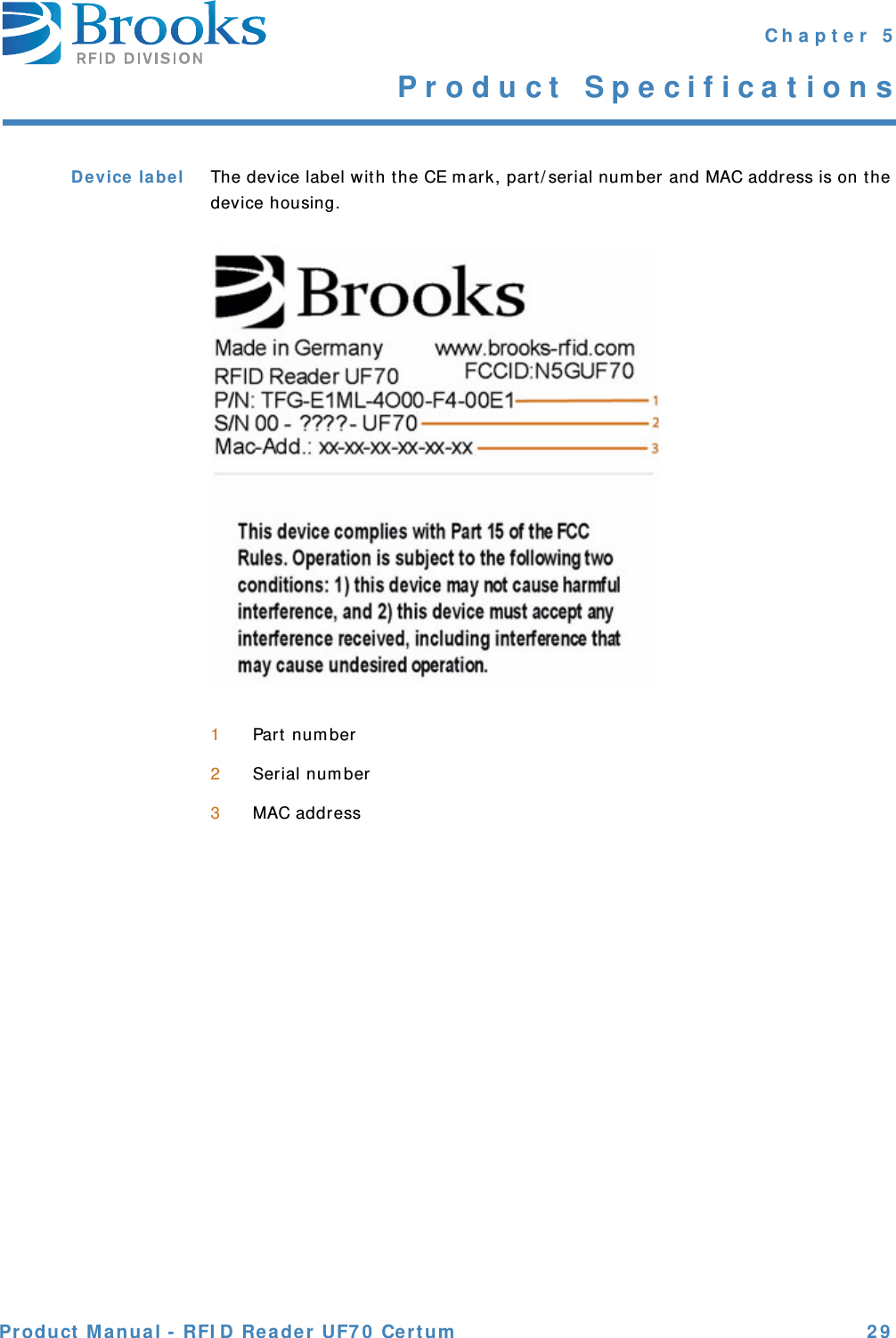
User Manual
3.
RF Exposure statement
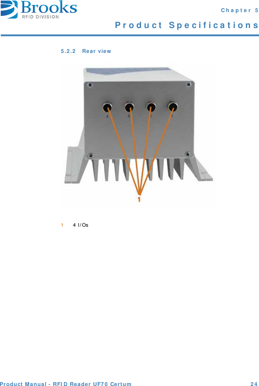
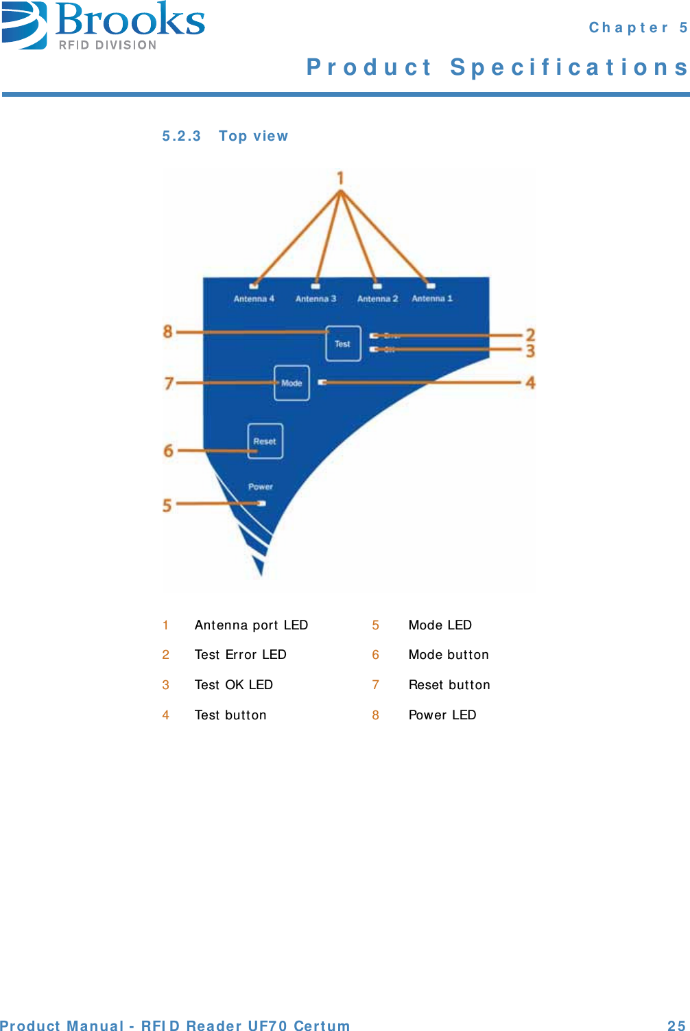
User Manual
Navigation menu
Upload a User Manual
Namespaces
Wiki Guide
HTML
PDF
Info
Views
User Manual
Discussion / Help
Navigation

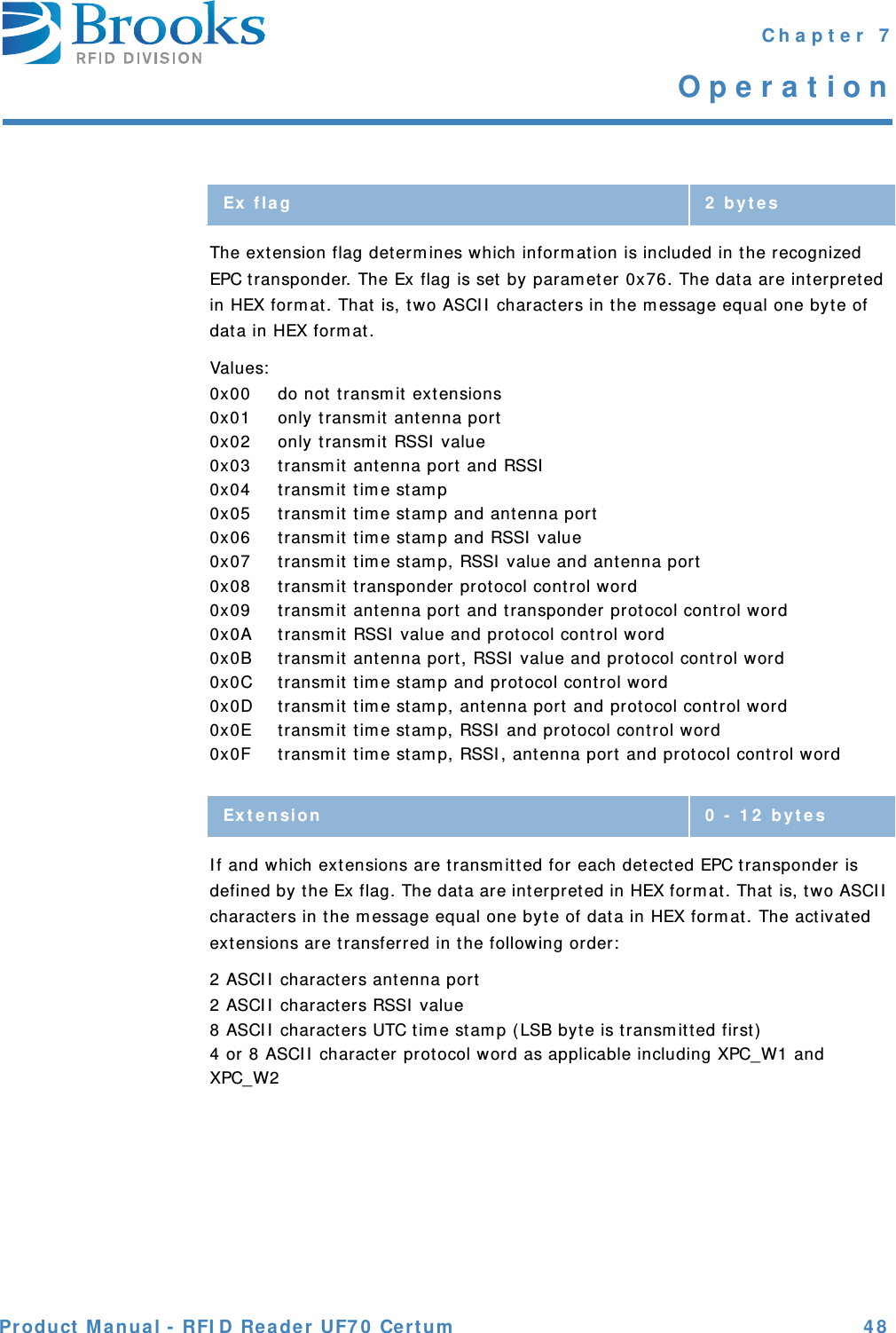
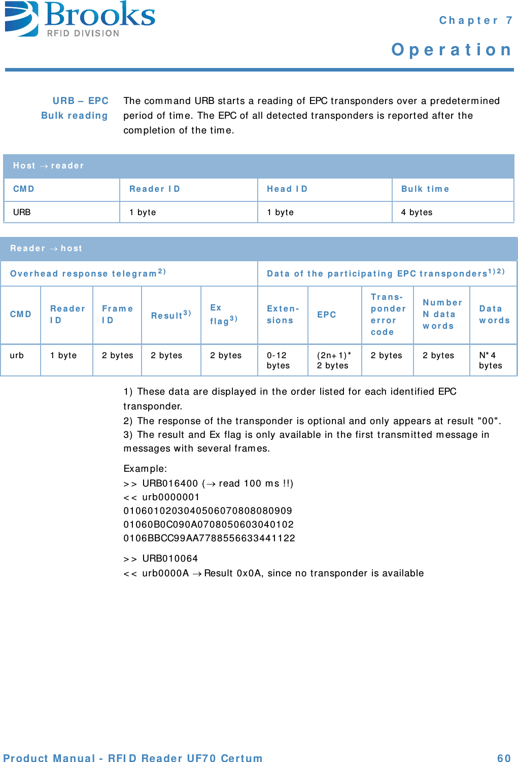
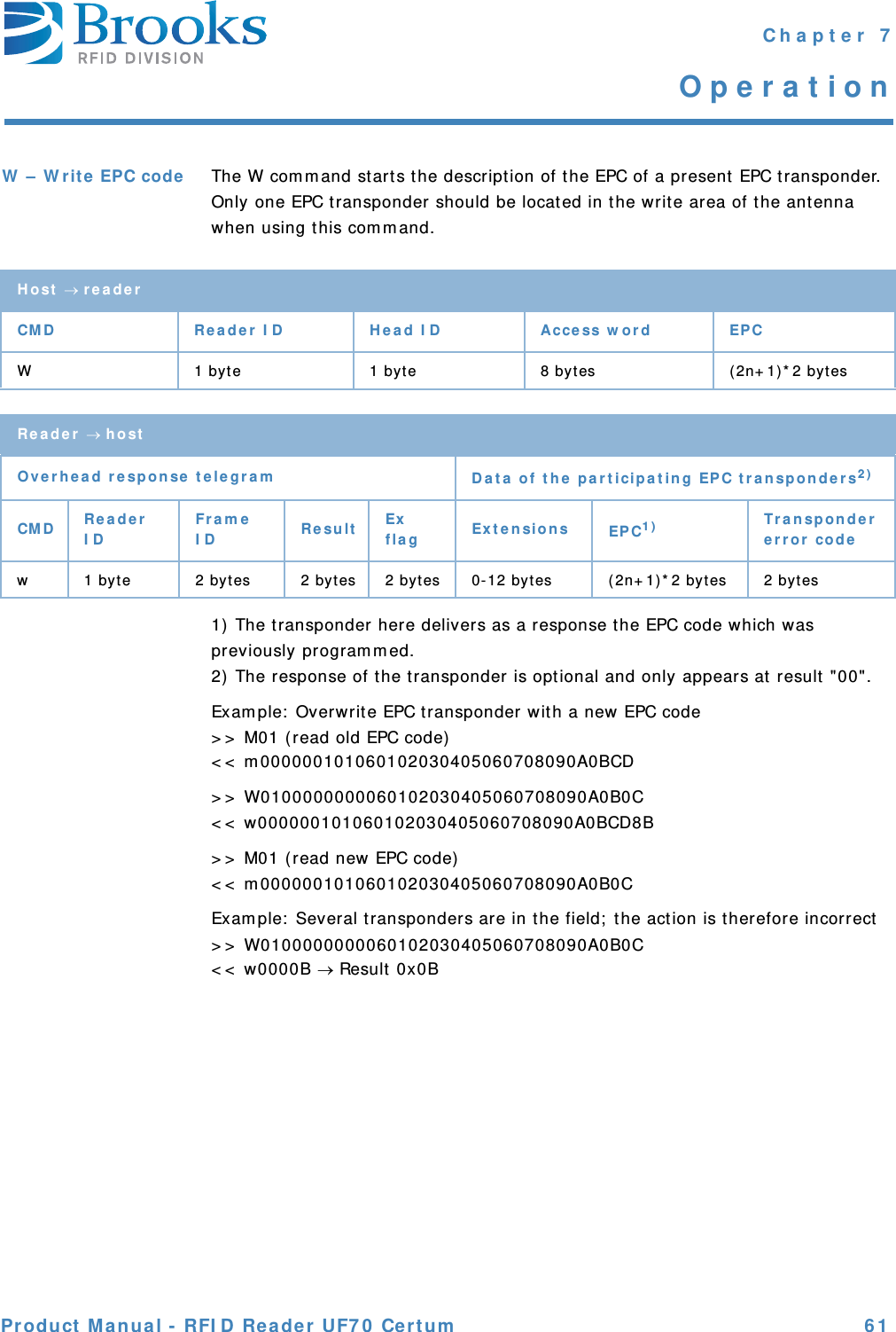
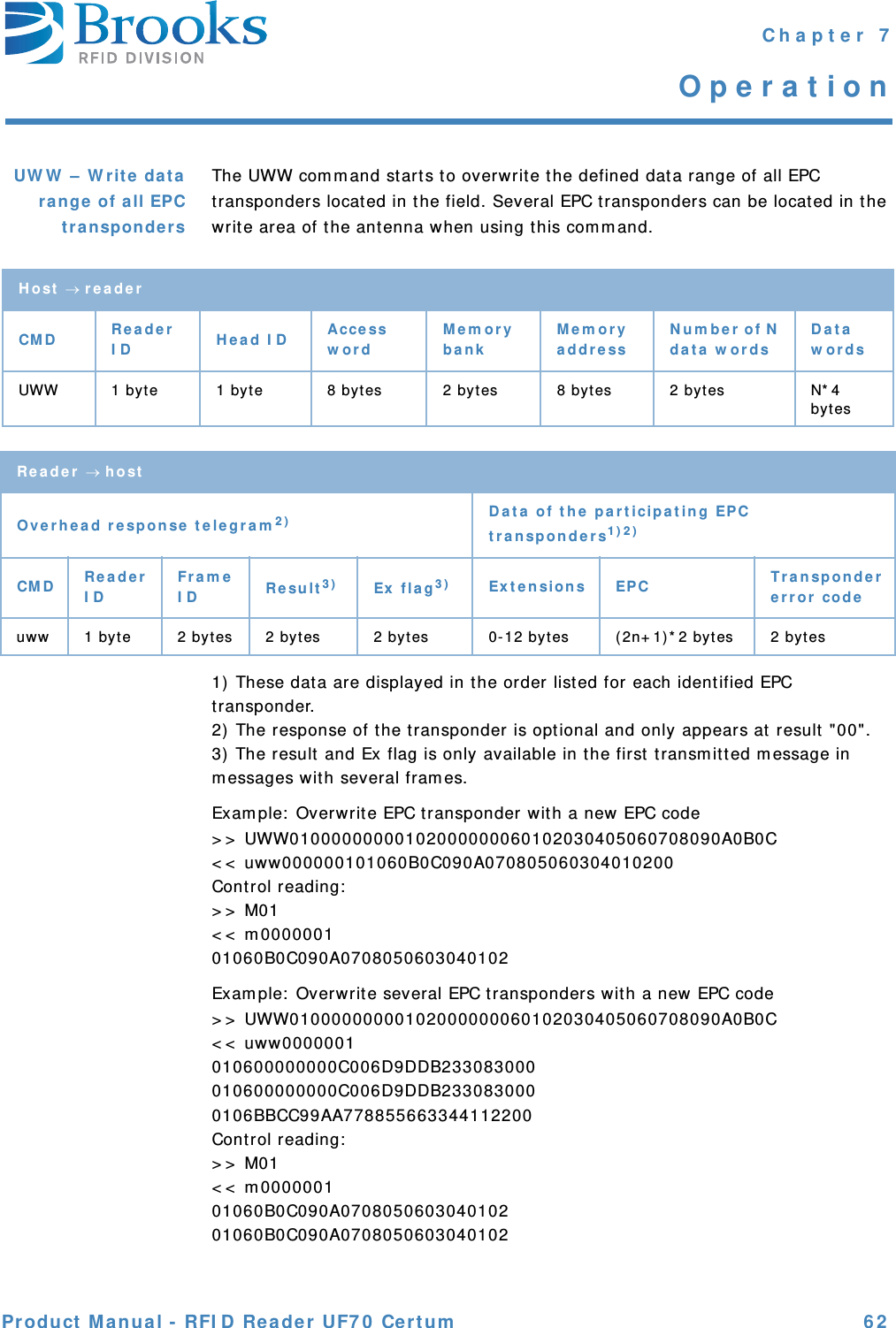
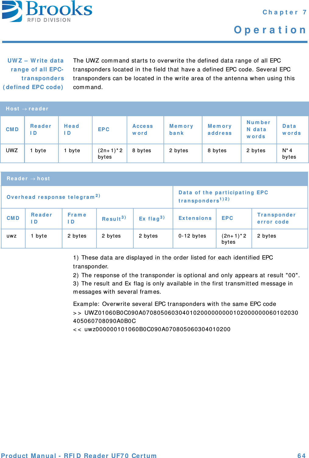
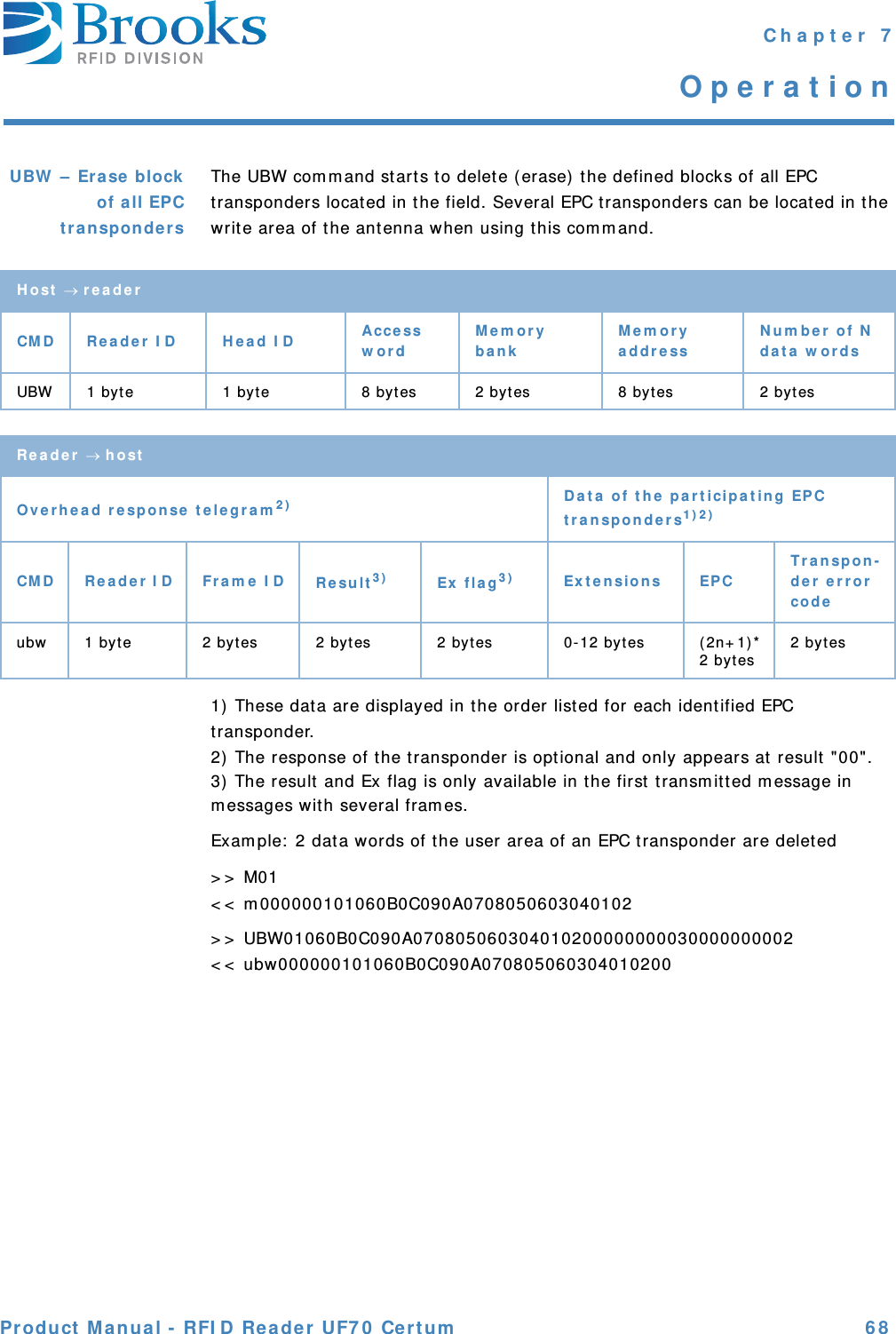
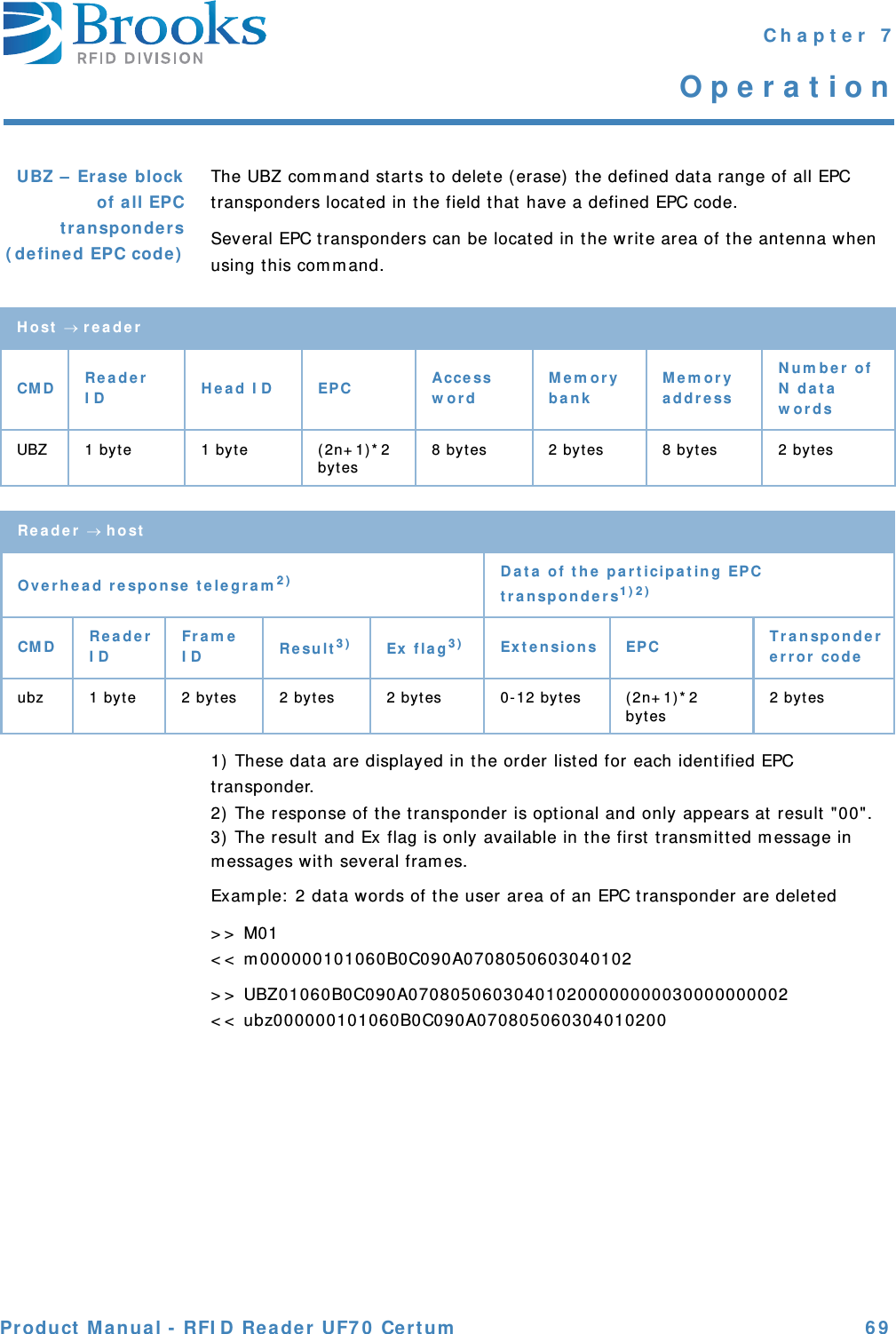
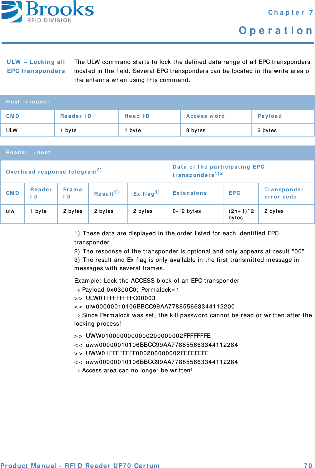
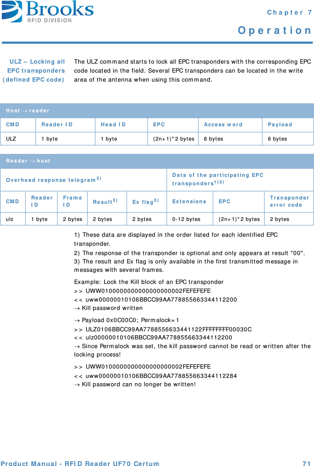
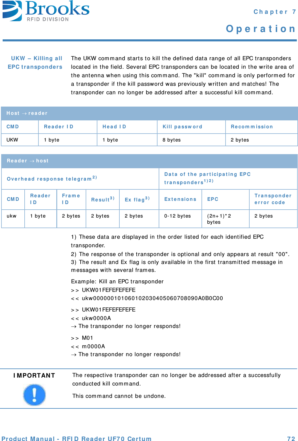
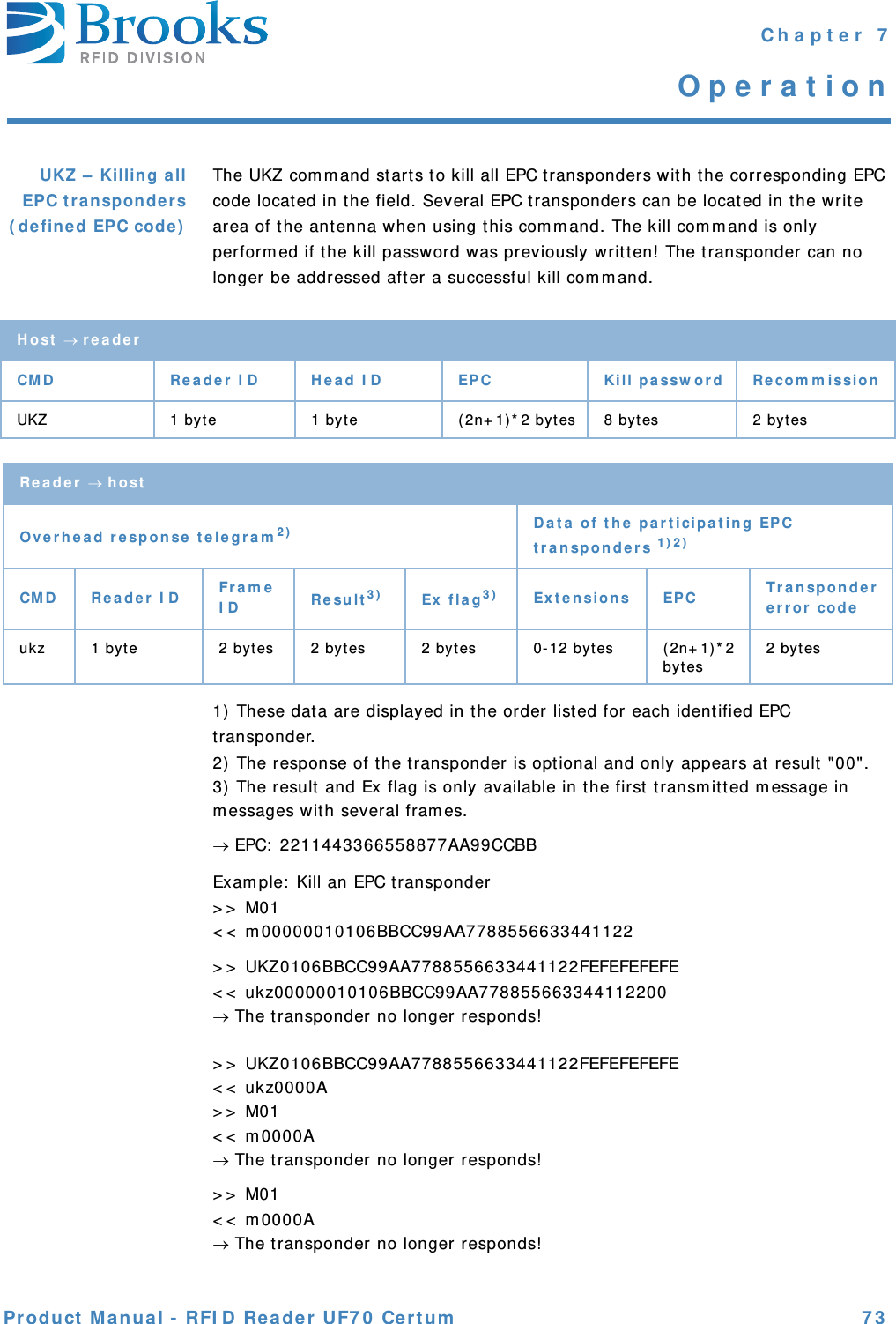
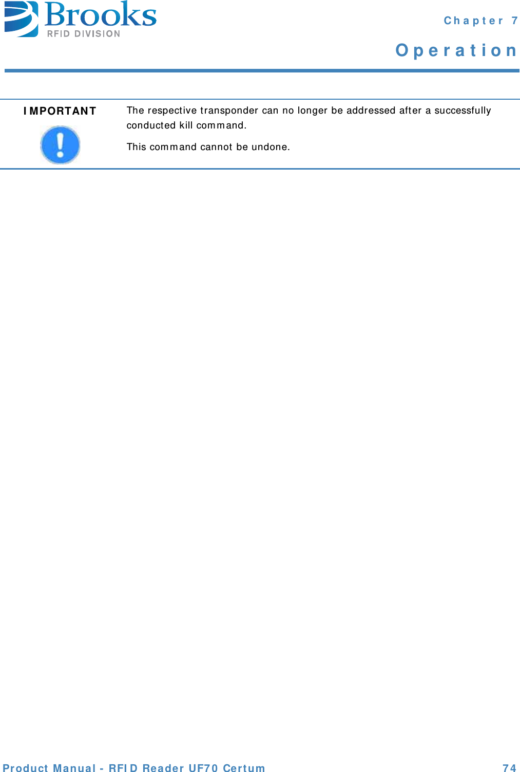
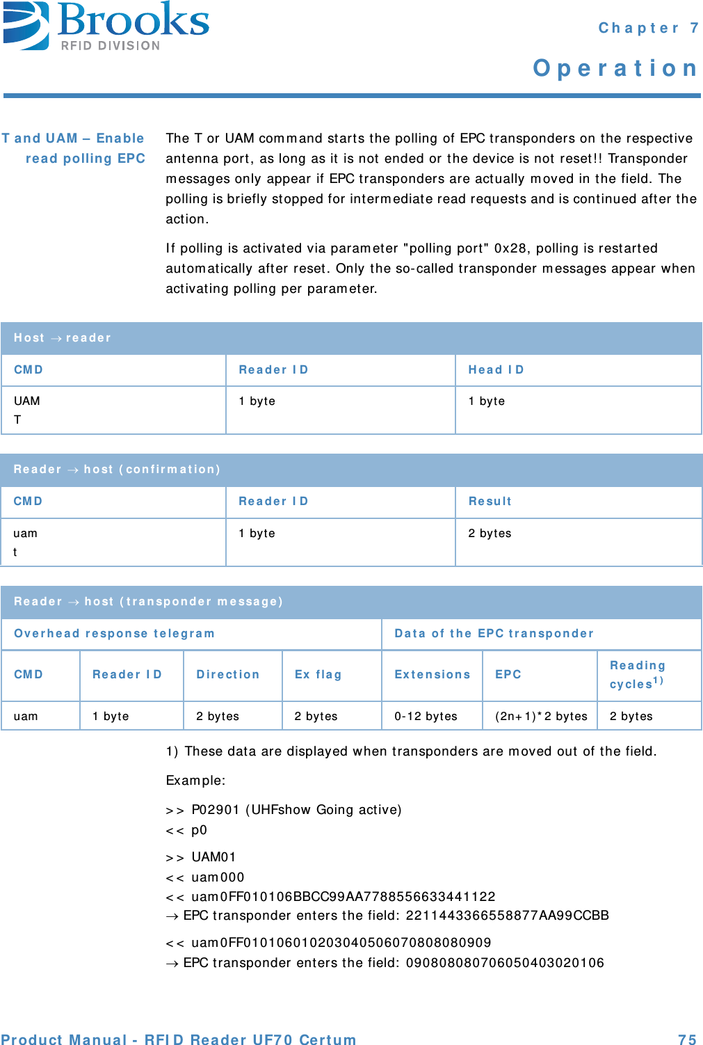
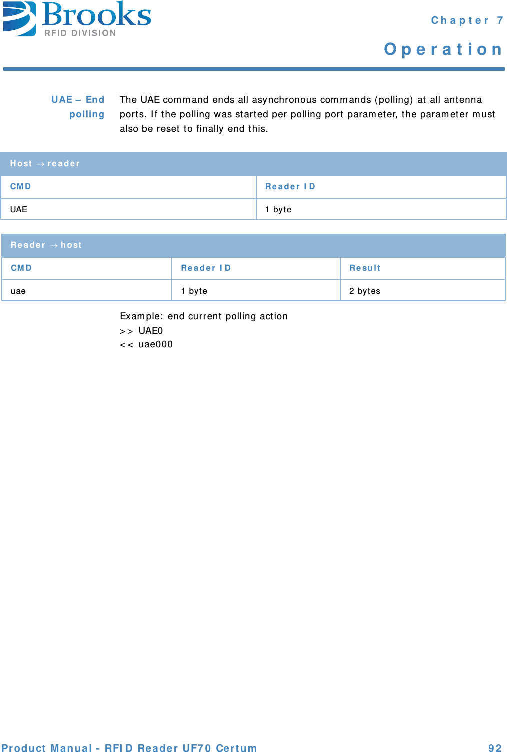
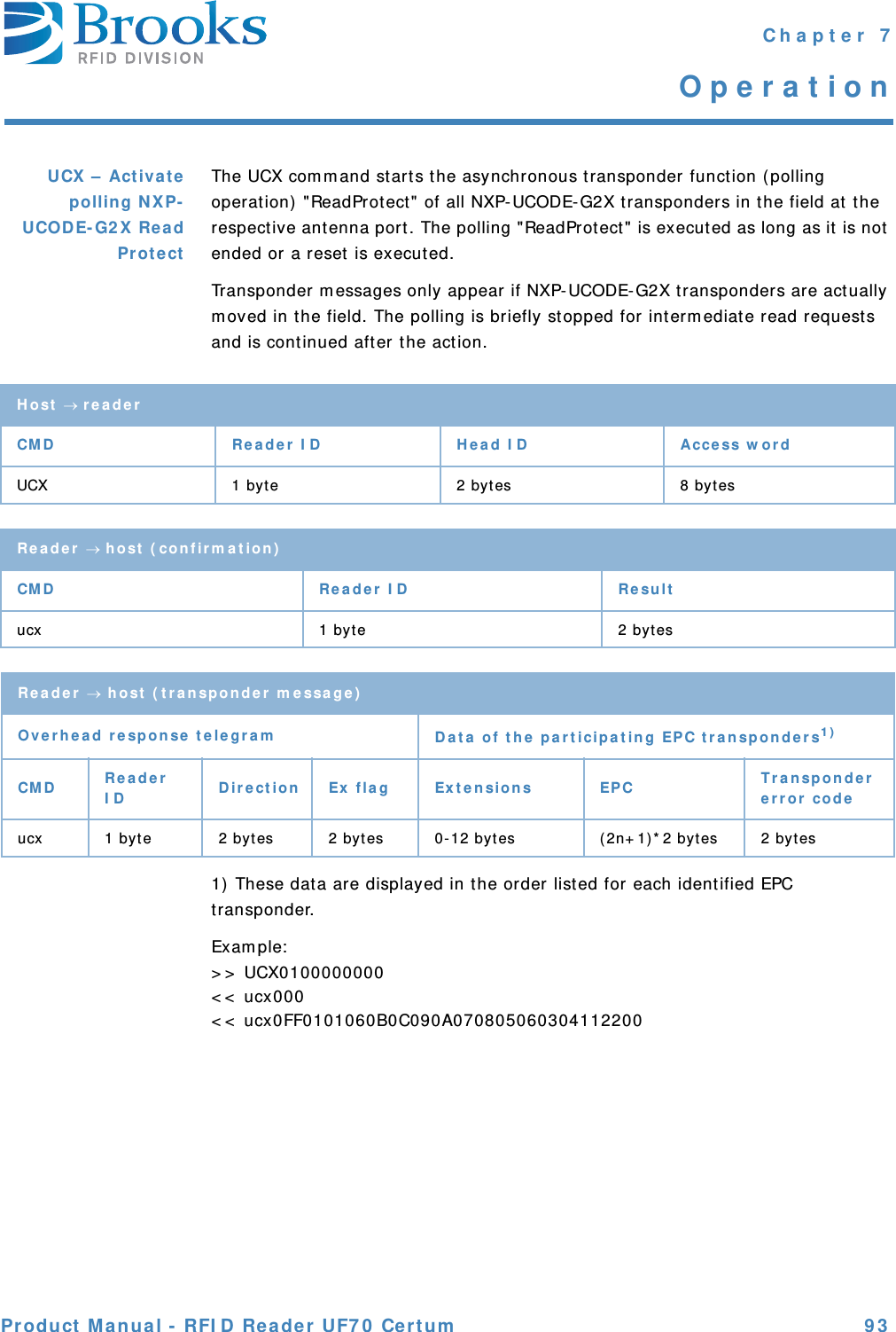
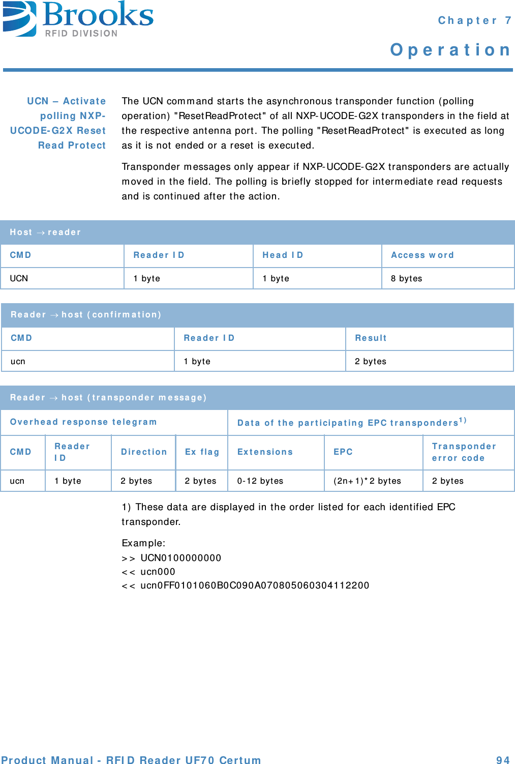
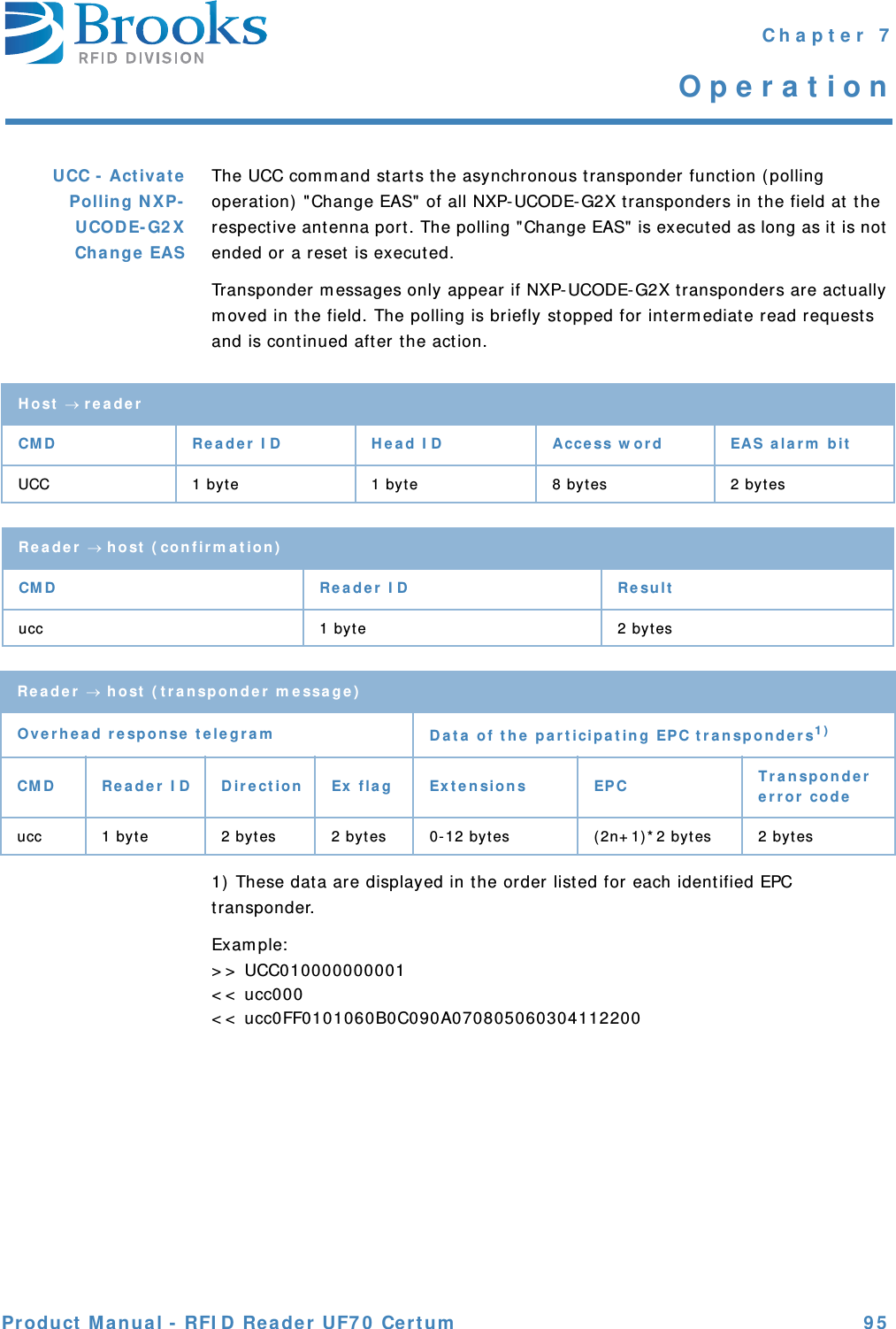
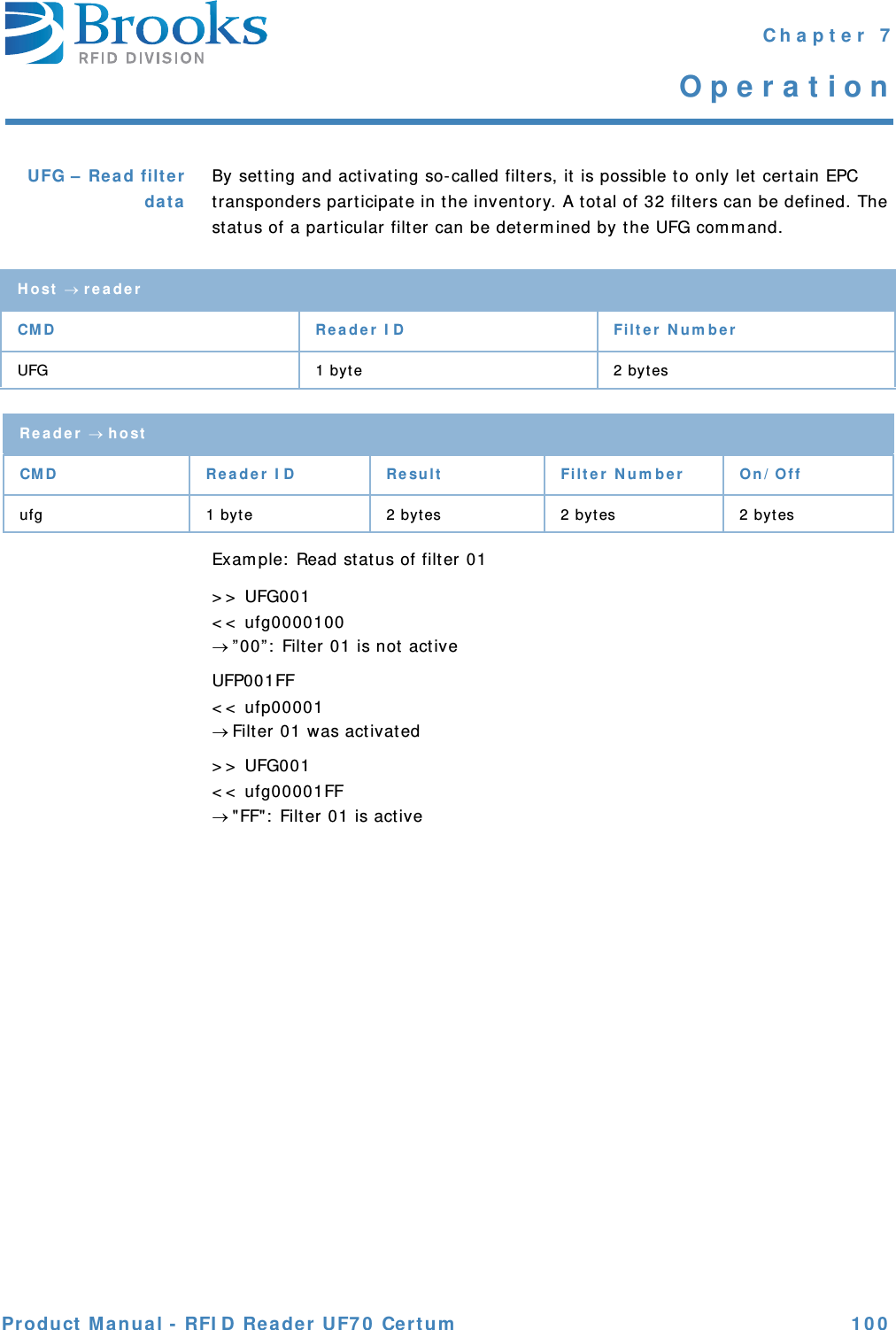
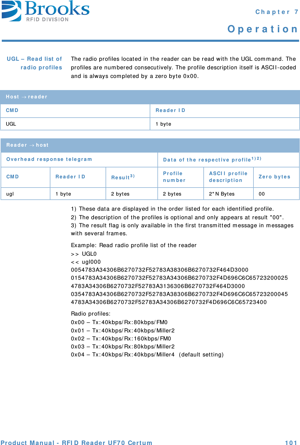
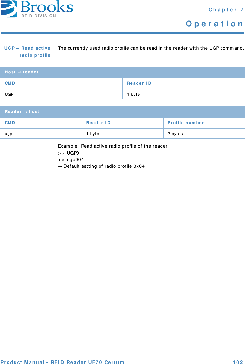
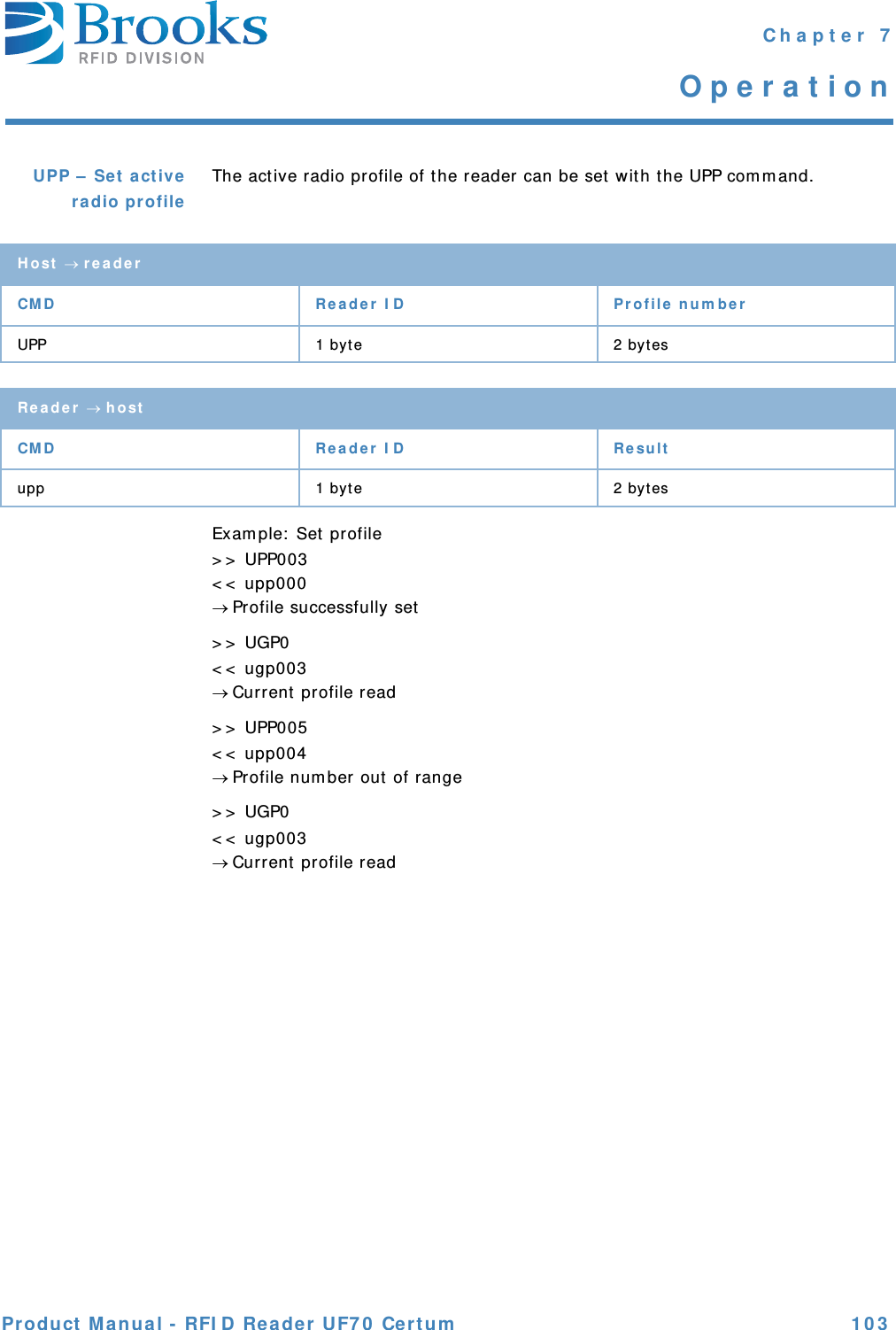
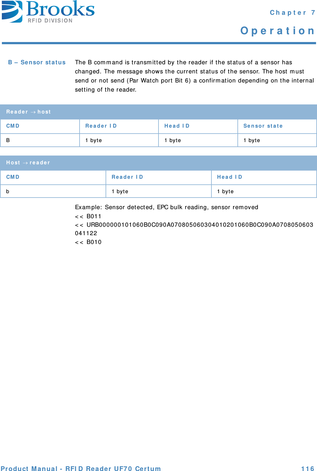
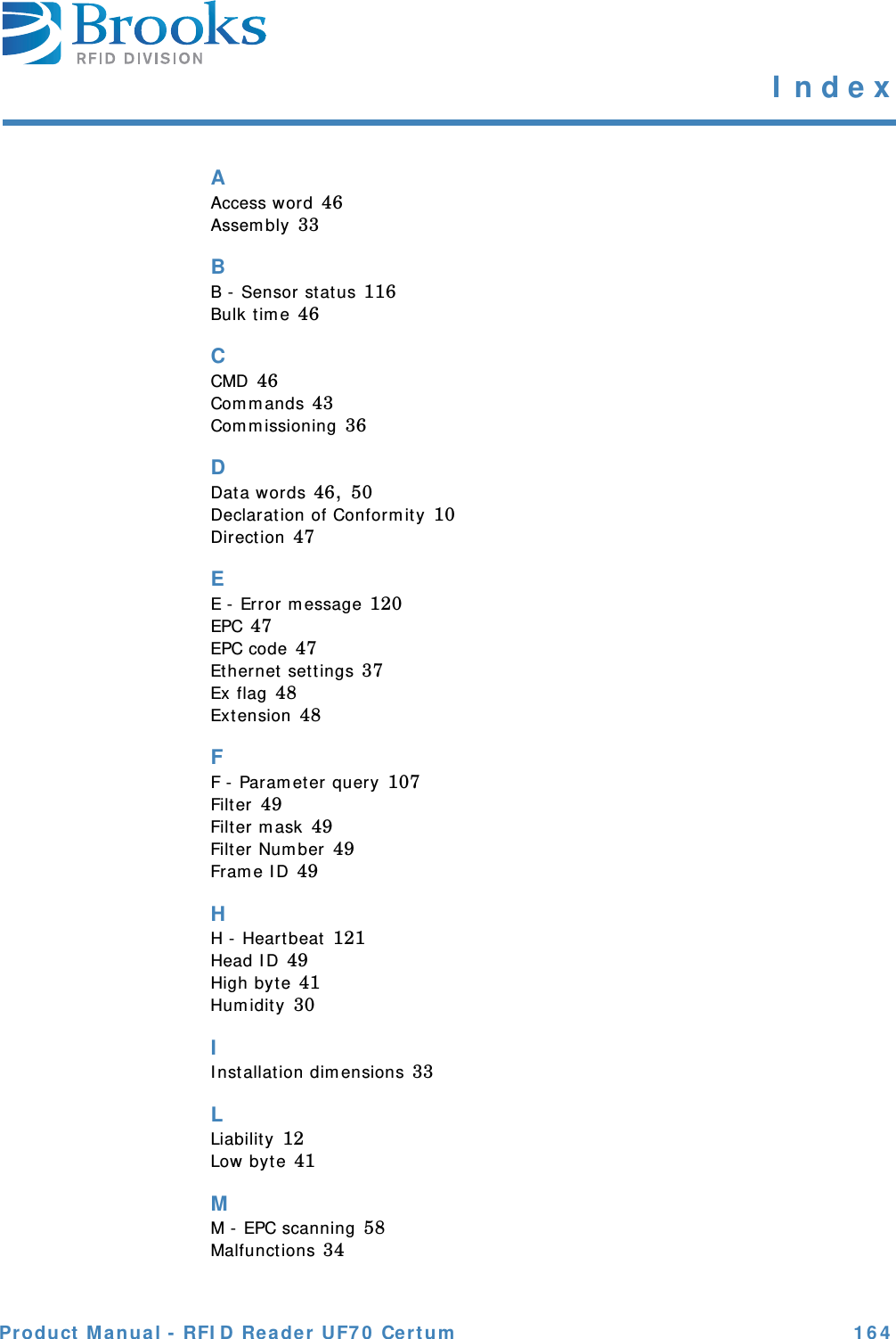
![Product M an ua l - RFI D Rea de r UF7 0 Cert um 1 3 1 Cha pt er 7Ope ra t ionPar a m e t er 0 4( 0 x 0 4 )MsgRe pe at De la y Tim e I f a confirm at ion is not sent by t he host , t he device waits t his t im e span before it sends t he m essage t o t he host again. The num ber of repet it ions is defined in param et er 6 ( MsgMaxRepeat ) .10 .. 250 [ 0.1 s]Default : 0x32 ( 5 s)Par a m e t er 0 6( 0 x 0 6 )MsgM a xRe pea t I f a confirm at ion is not sent by the host, the device repeat s t he m essage according t o t he set value. Only t hen is an error m essage sent .0 – 31Default : 0x03Par a m e t er 0 7( 0 x 0 7 )First byt e of t he se ria l nu m be r ( r e a d on ly)Represent s t he first byte of t he serial num ber Device label.This value is writ e prot ect ed!Par a m e t er 0 8( 0 x 0 8 )Secon d byt e of t h e ser ia l nu m be r ( re a d on ly)Represent s t he second byt e of t he serial num ber Device label.This value is writ e prot ect ed!Par a m e t er 1 1( 0 x 0 B)Re a de r I D This param et er defines t he addr ess of t he device in t he ASC-I 1 protocol.0 .. EDefault : 0x00Par a m e t er 1 2( 0 x 0 C)Ack n ow le dgm ent Err or M essage This param et er defines whether an error m essage m ust be confirm ed or not .0 – No confirm at ion expect ed1 – a confirm at ion is expectedDefault : 0x01](https://usermanual.wiki/Brooks-Automation/UF70.User-Manual/User-Guide-1710606-Page-131.png)