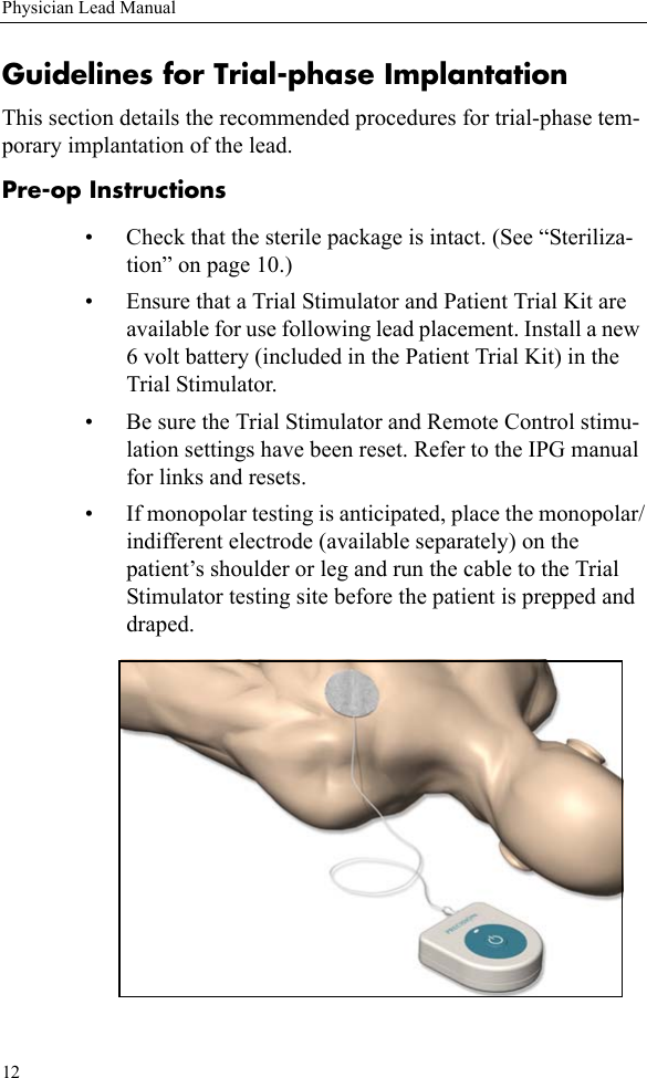
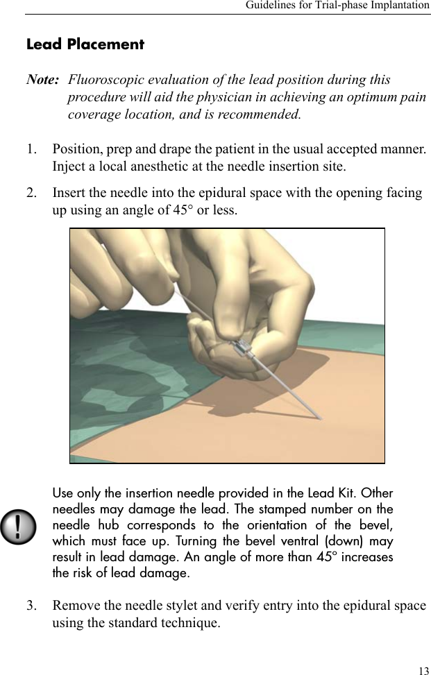
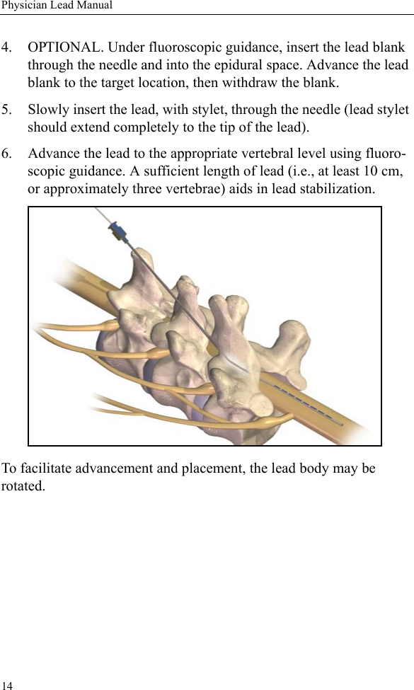
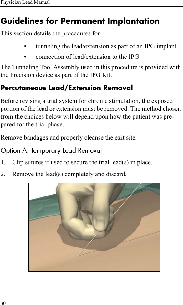
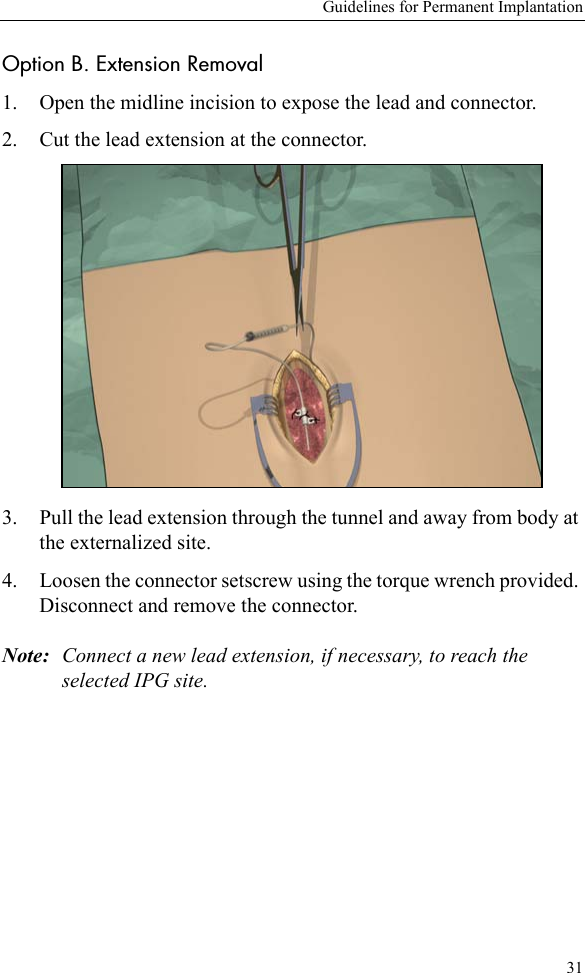
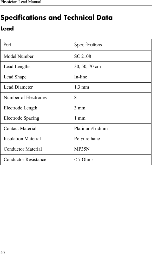
Boston Scientific Neuromodulation SC-5100 SCS Implant System External Trial Stimulator User Manual SCS Dr Covers
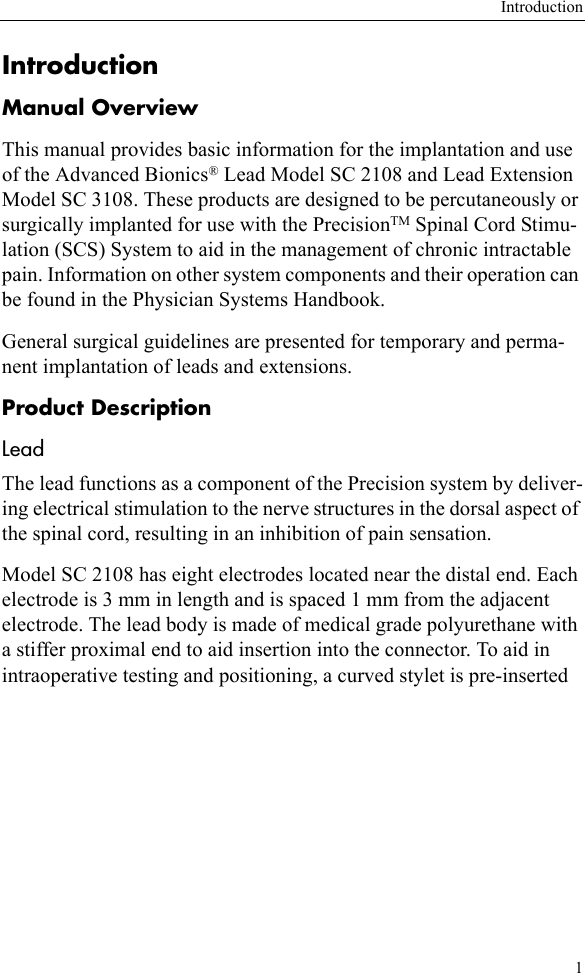
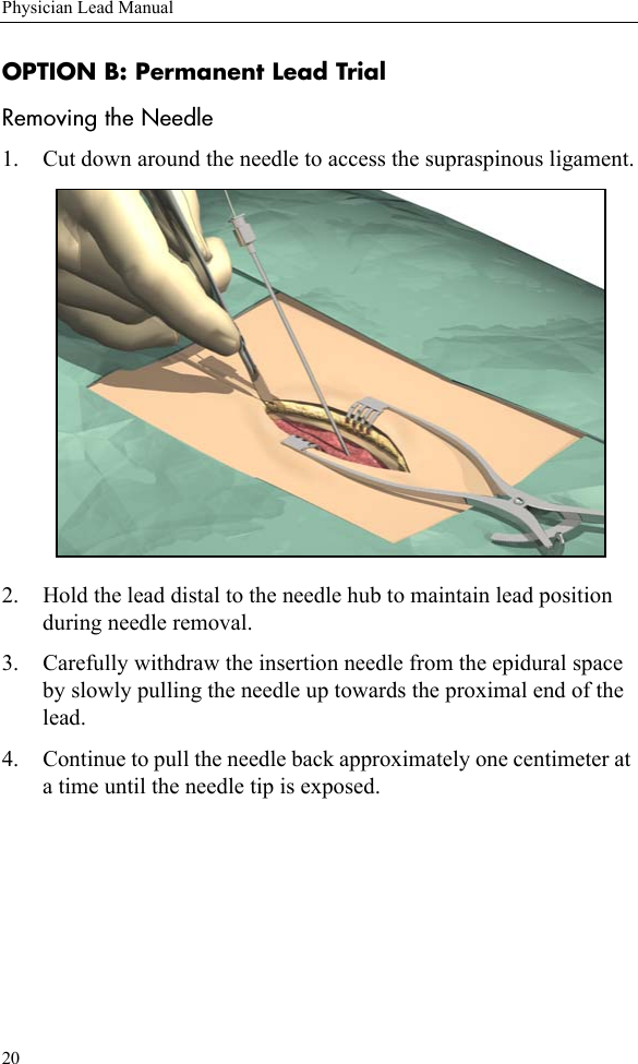
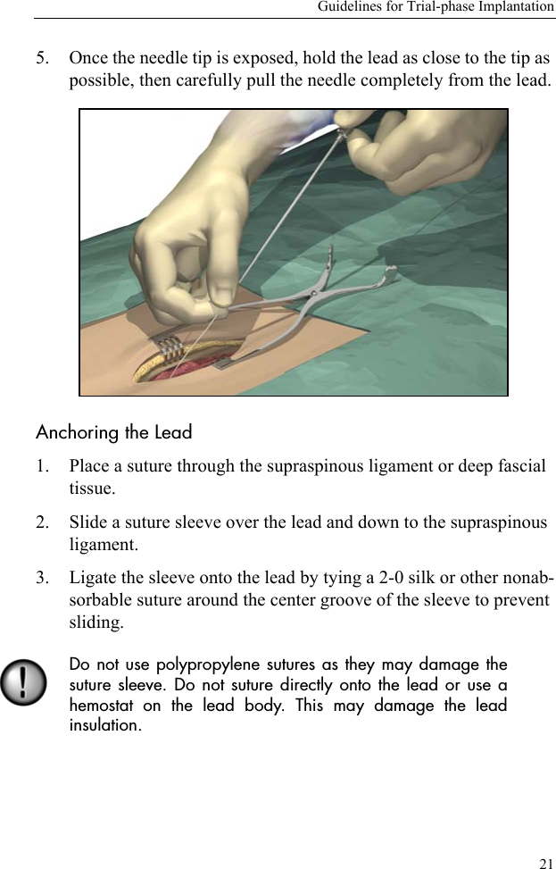
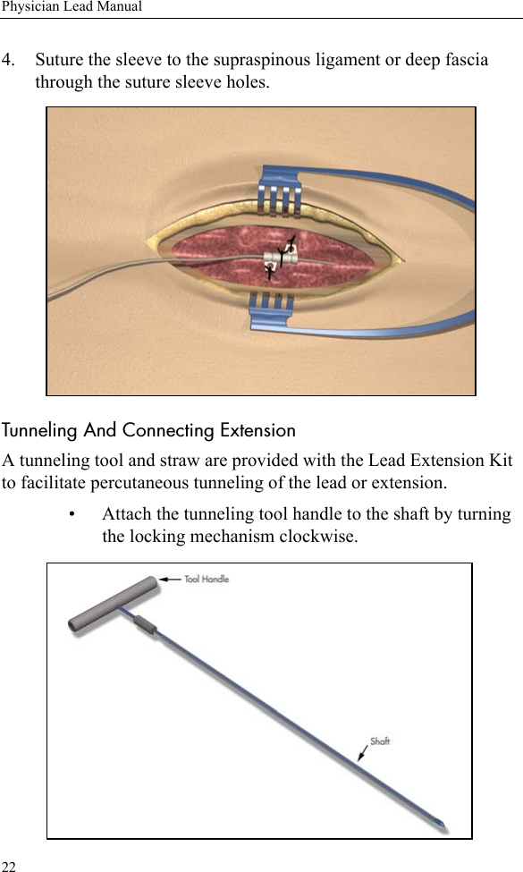
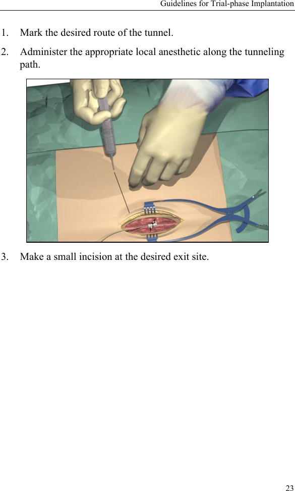
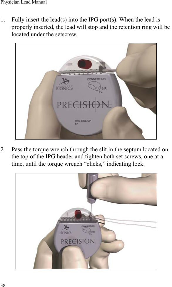
Boston Scientific Neuromodulation Corporation SCS Implant System External Trial Stimulator SCS Dr Covers
Contents
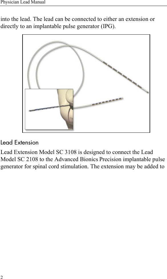
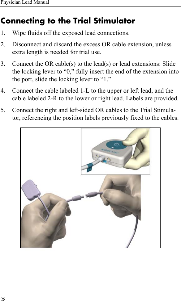
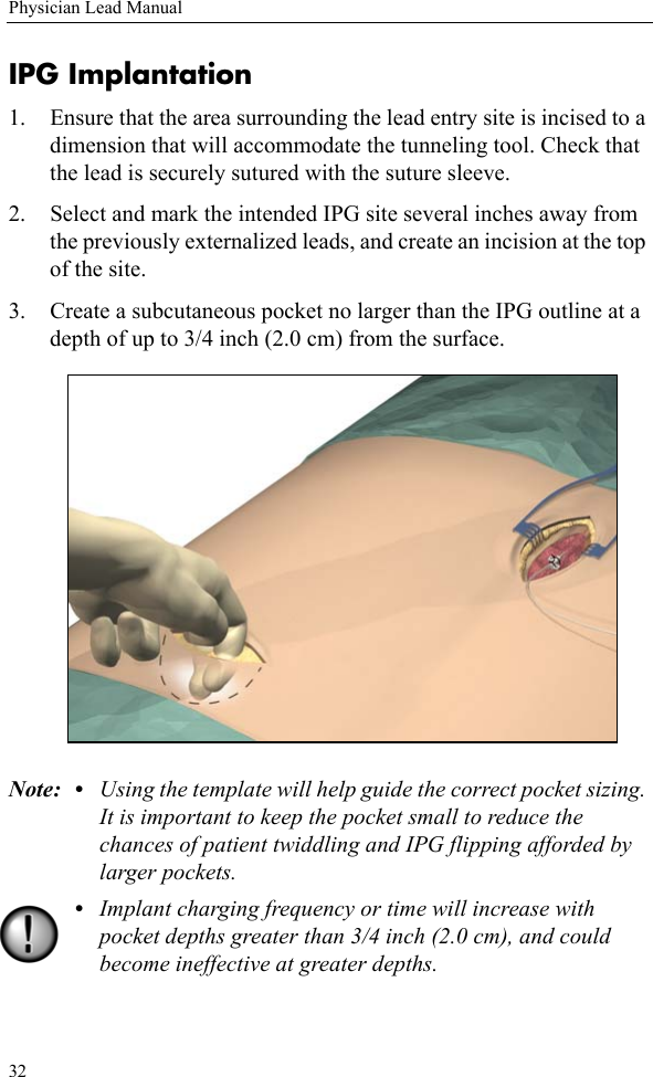
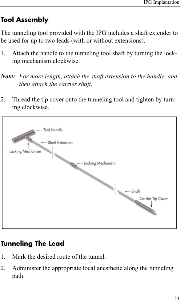
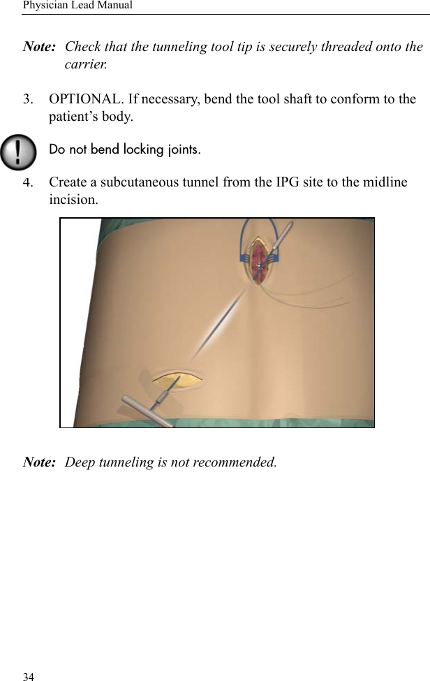
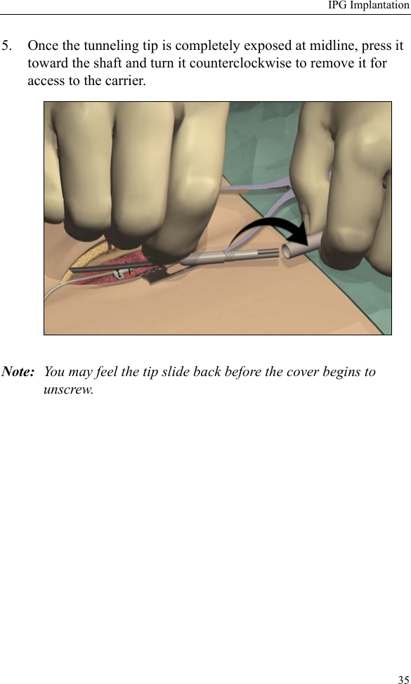
- 1. patient system handbook
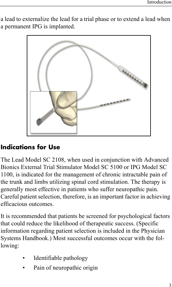
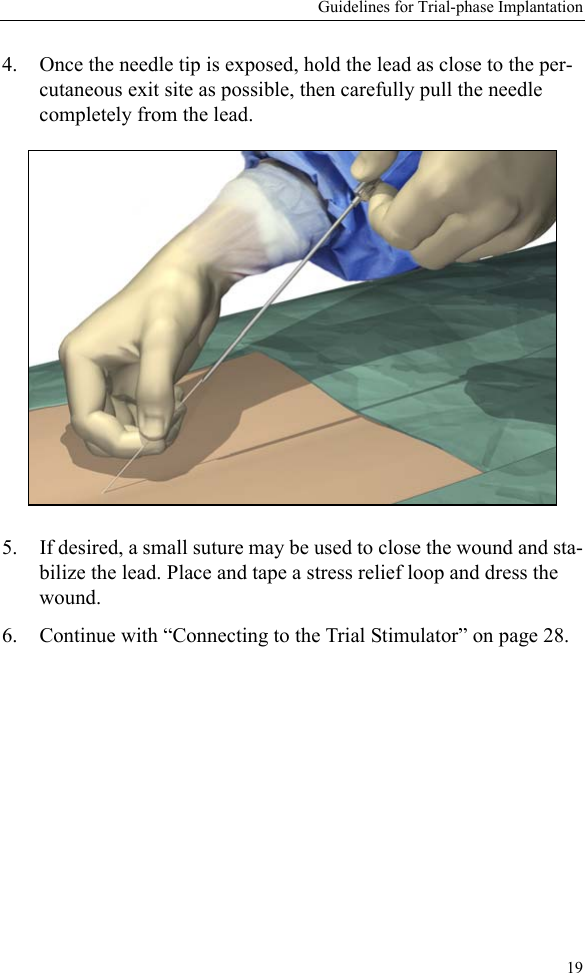
- 2. patient trial handbook
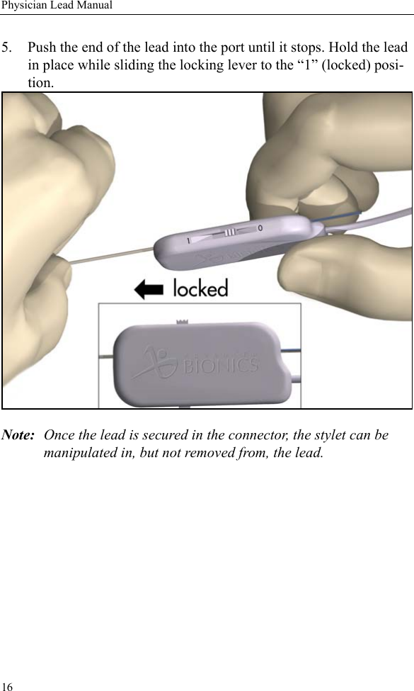
- 3. manual insert
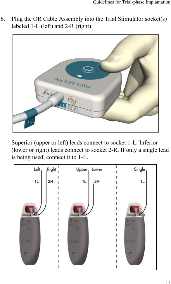
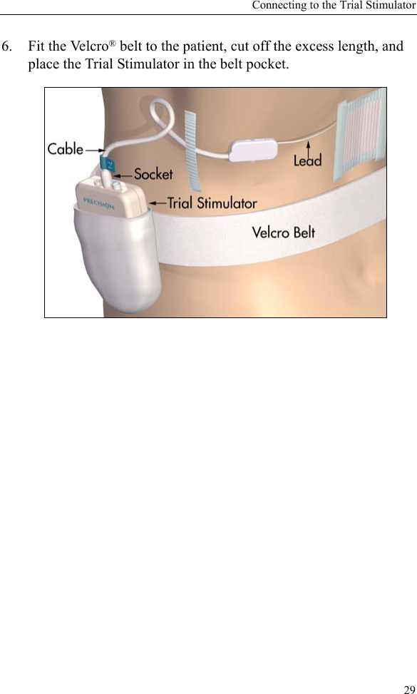
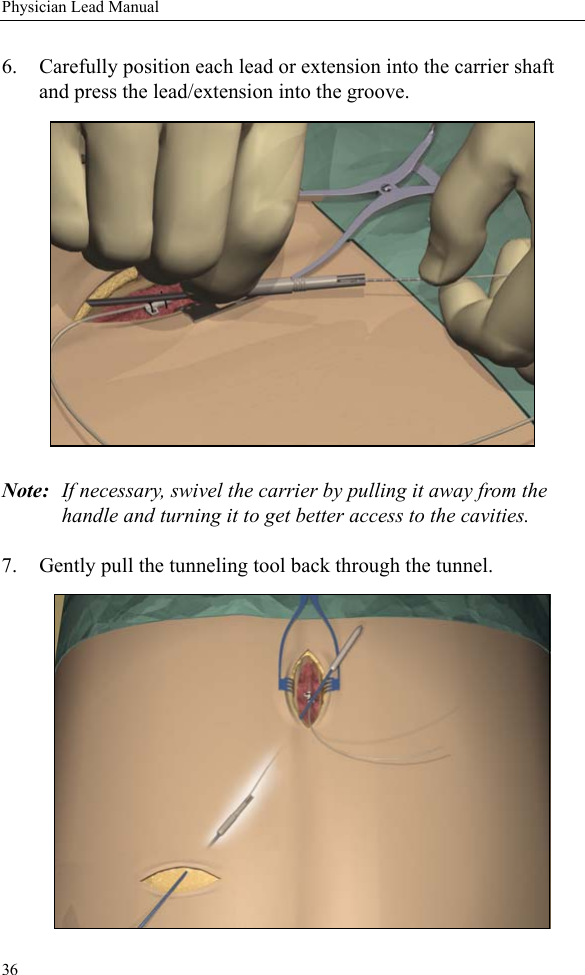
- 4. physician lead manual
- 5. physician implant manual
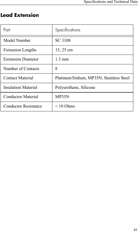
physician lead manual