Boston Scientific Neuromodulation SC-5100 SCS Implant System External Trial Stimulator User Manual SCS Dr Covers
Boston Scientific Neuromodulation Corporation SCS Implant System External Trial Stimulator SCS Dr Covers
Contents
- 1. patient system handbook
- 2. patient trial handbook
- 3. manual insert
- 4. physician lead manual
- 5. physician implant manual
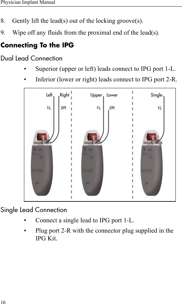
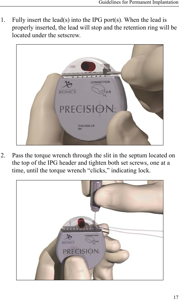
physician implant manual


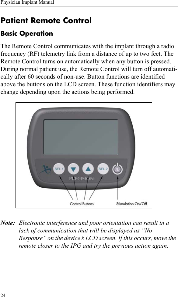
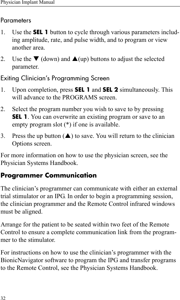
![Patient Remote Control25Basic ProgrammingStimulation On/OffThe stimulation is turned on and off with a dedicated power switch on the Remote Control keypad. Simply press the stimulation power but-ton at any time to change the on/off state of the implant. Stimulation Amplitude Press the T or S button from the main screen to decrease or increase amplitude. Coverage Area SelectionPress the SEL 1 [SEL] button from the main screen to cycle to a spe-cific stimulation coverage area. Press the T or S button to adjust the amplitude of the selected area. Program SelectionPress the SEL 2 [NEXT] button to display the program screen. Press the SEL 1 [SEL] button to cycle through saved programs. Program selections can be either activated (press T) or saved (press S) from this screen.](https://usermanual.wiki/Boston-Scientific-Neuromodulation/SC-5100.physician-implant-manual/User-Guide-356450-Page-32.png)
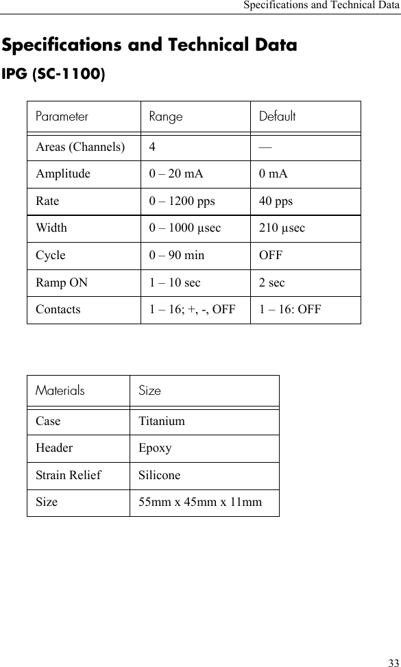
![26Physician Implant ManualOptions Press and hold the SEL 2 button for 3 seconds to access the Rate and (Pulse) Width parameters and the program restore function. Use the SEL 1 button to highlight the desired option, then press S [GO]. Note: Rate and Pulse Width are blocked from patient access by default, but may be made available using the Clinician’s Programmer.](https://usermanual.wiki/Boston-Scientific-Neuromodulation/SC-5100.physician-implant-manual/User-Guide-356450-Page-33.png)
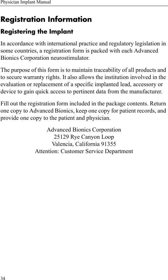
![Patient Remote Control27For Rate and Pulse Width: When the desired option screen is dis-played, first use the SEL 1 button to find the desired area, then use the T or S button to decrease or increase the parameter setting for that area. To restore a program: Press SEL 1 to highlight the desired program, then press SEL 2 [RESTR]. The restore function returns a program to the last clinic programmed settings.Physician ModePatient-restricted physician screens provide access to these advanced programming and interrogation functions:• Communication with the clinician programmer • Electrode and stimulation parameter programming • Electrode impedance monitoring • Remote Control and trial stimulator resetting/re-linkingEntering Physician Mode1. To access physicians screens, press SEL 1 and SEL 2 simulta-neously.2. The Remote Control will request a code. (To obtain the code, refer to the Physician Systems Handbook.) Use the S and T buttons to scroll through the characters, and the SEL 1 [SEL] but-ton to advance to the next entry. After entering the code, press SEL 2 [ENTER]. Once the code is entered, the screen will appear as shown.](https://usermanual.wiki/Boston-Scientific-Neuromodulation/SC-5100.physician-implant-manual/User-Guide-356450-Page-34.png)
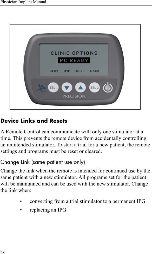
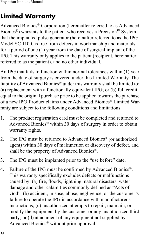
![Patient Remote Control29Change Patient When a Remote Control is to be used with a different patient than was previously using the remote, reset the system. This will clear all pre-viously stored programs and will allow you the option of resetting a trial stimulator when one is detected. Always reset the system when using a remote with a different patient, such as when:• Programming an IPG or trial stimulator of a new or dif-ferent patientChanging Links and Resets1. Access the physician mode and enter the code.2. When the screen displays “CLINIC OPTIONS PC READY” press S [RSET] to access the links and resets.3. Use SEL 1 to select “Link” or “Patient” from the following screen, and press S [RSET].](https://usermanual.wiki/Boston-Scientific-Neuromodulation/SC-5100.physician-implant-manual/User-Guide-356450-Page-36.png)
![30Physician Implant ManualThe Remote Control will turn off after breaking the existing link and/or clearing the programs. Press any button to turn on the remote and re-establish the link. Reading Lead ImpedancesFrom the physician OPTIONS screen, press T [IMP] to check lead electrode impedances. It will take a few seconds to display the detected values. Note: Failed electrodes that are not currently assigned will not be displayed on the programming screen. Otherwise, failed anodes will be displayed H+. Failed cathodes will be displayed H-. You may wish to make note of problem contacts from this screen to serve as a programming reference.Stimulation Set Up (Programming)Note: When using the Remote Control for a new or different patient, be sure it has been reset. See “Change Patient” on page 29 for instructions.1. Enter the physician mode (see “Entering Physician Mode” on page 27) and press SEL 1 [CLIN] to access the programming screen. 2. The SEL 2 button toggles between the electrode configuration and the parameters.The screen displays the settings and configuration for one program-mable area at a time. Up to four independent areas can be configured for each of the four programs available with the IPG.When there are separately controlled areas of stimulation, thestimulation rates for the individual areas must be in descendingorder or be equal. This means that Area 1 must have a ratehigher than or equal to Area 2, and Area 2 must have a ratehigher than or equal to Area 3, and so forth. (Coverage areasare separate groups of electrodes, with independent](https://usermanual.wiki/Boston-Scientific-Neuromodulation/SC-5100.physician-implant-manual/User-Guide-356450-Page-37.png)