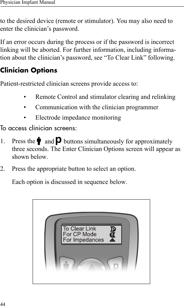
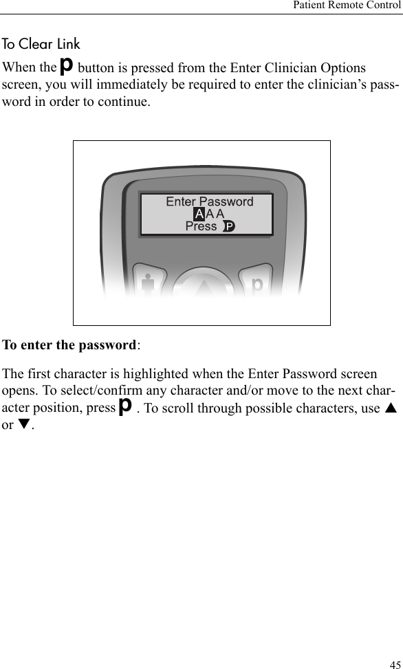
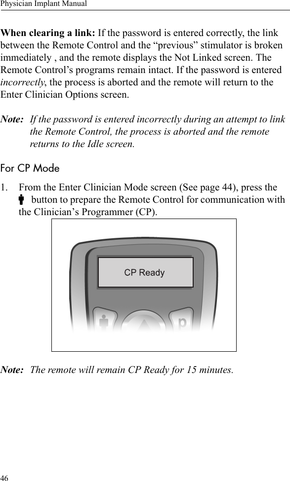
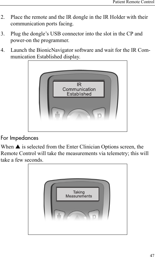
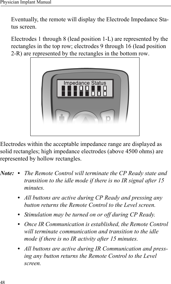
Boston Scientific Neuromodulation PSC1110W Precision SCS System Implantable Pulse Generator User Manual II Physicans Implant
Boston Scientific Neuromodulation Corporation Precision SCS System Implantable Pulse Generator II Physicans Implant
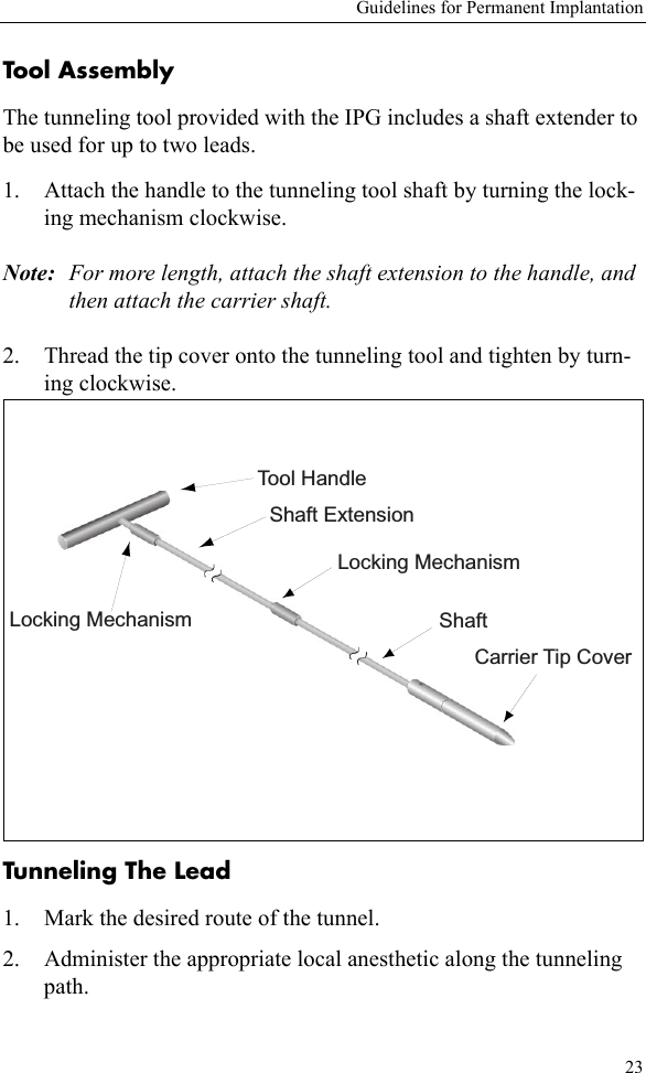
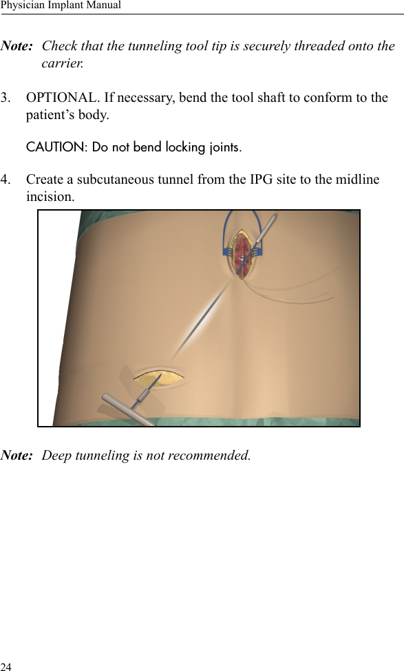
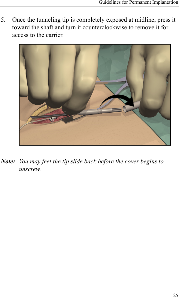
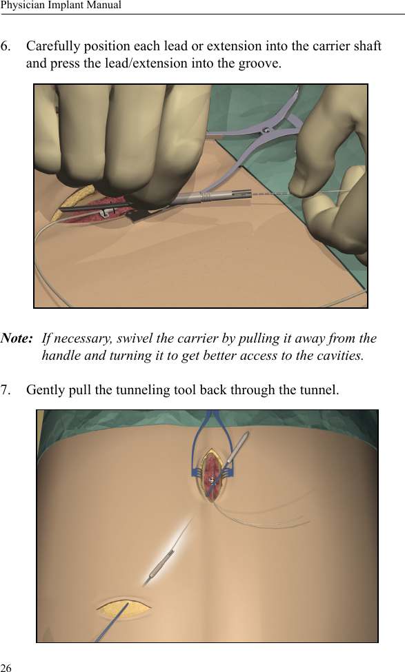
Contents
- 1. Patient Handbook
- 2. Patient Trial Guide
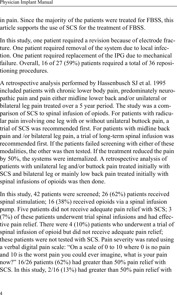
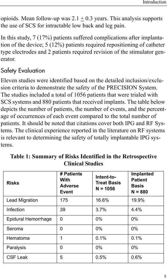
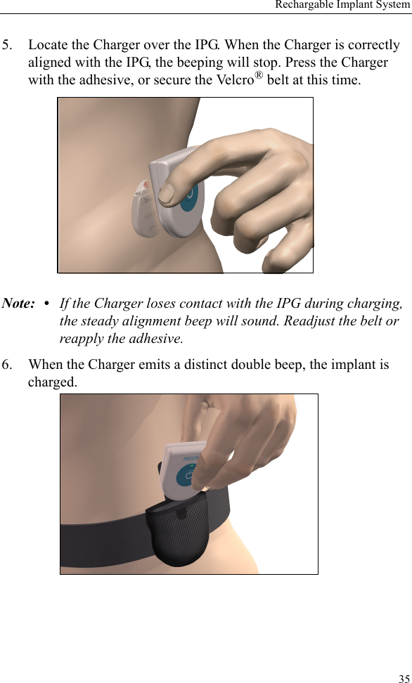
- 3. Physicians Implant Manual
- 4. Physician Trial Kit Insert
- 5. Lead Manual
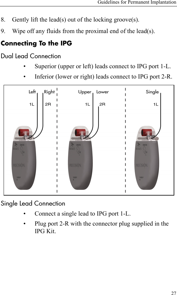
Physicians Implant Manual