Blue Tower Communications EM915CV1 Electric Meter Reading Transmitter User Manual Part 2
Blue Tower Communications Ltd Electric Meter Reading Transmitter Part 2
UserManual.wiki
>
Blue Tower Communications
>
EM915CV1 User Manual
>
Part 2
Contents
1.
Part 1
2.
Part 2
Part 2
Navigation menu
Upload a User Manual
Namespaces
Wiki Guide
HTML
PDF
Info
Views
User Manual
Discussion / Help
Navigation
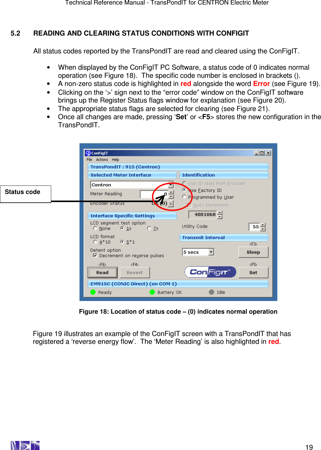
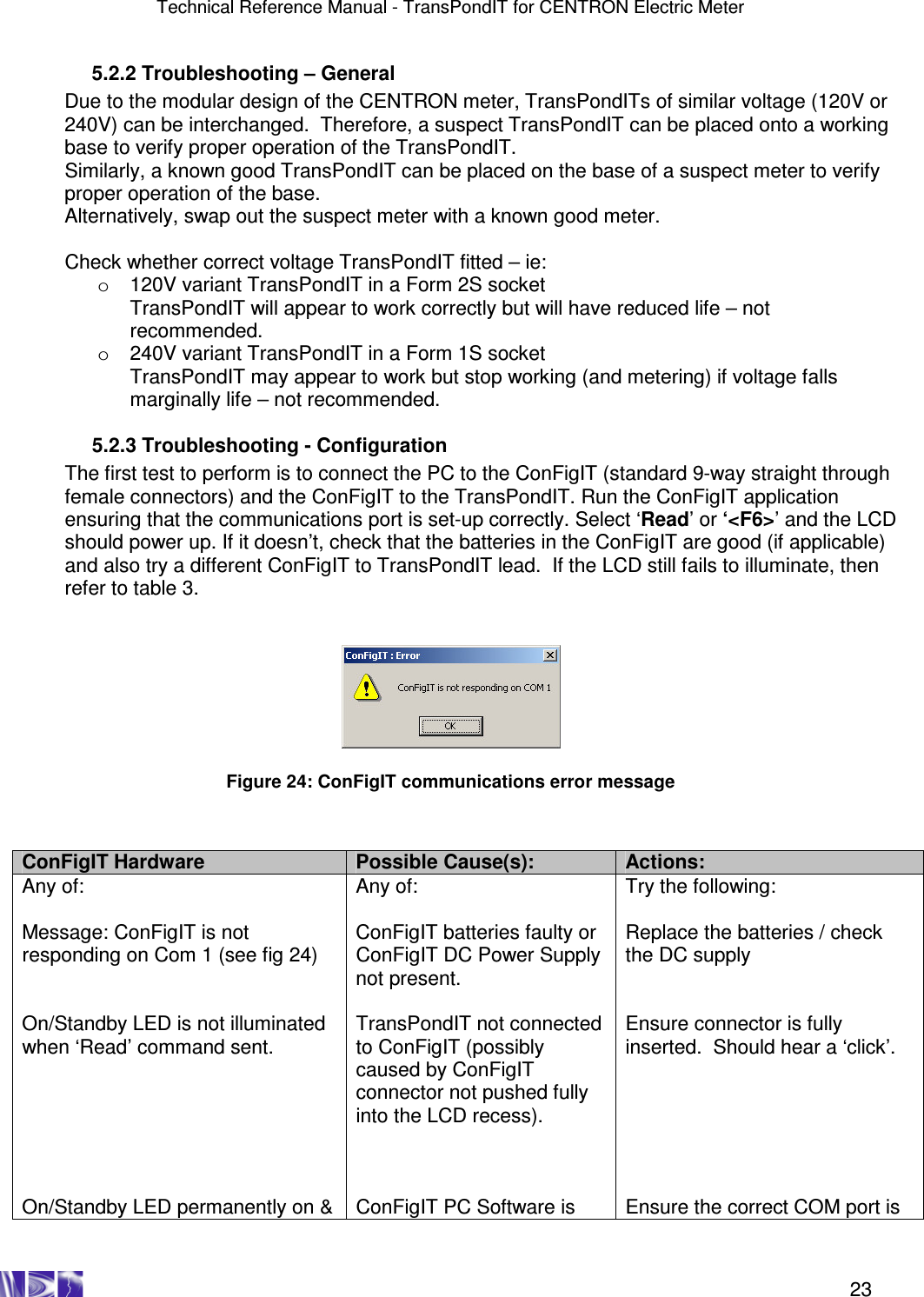
![Technical Reference Manual - TransPondIT for CENTRON Electric Meter 27 APPENDIX C: STATUS CODE TROUBLESHOOTING It is expected that all of these troubleshooting operations are performed in the meter shop – after the meter is withdrawn. Figure C-1 Reverse energy flow Note: the reverse energy flow flag is for information purposes. It does not mean that the TransPondIT is faulty.Was the meter fitted upside down? Follow utility procedures for removing and re-fitting meter in the correct orientation If appropriate, clear the status code and check that TransPondIT is counting correctly. Refer to chapters 3 & 5 END Report finding to appropriate utility personnel Call RAMAR Technical Support 1-888-987-2627 YES NO NO YES YES NO Reverse Energy Flow [01] Confirm metrology board function by substituting another TransPondIT and checking for correct operation. Working OK? YES Is there any physical damage? NO Confirm correct operation of the meter. (i.e. Meter reading increments. LCD reading and radio reading are as set by configuration). Note: If the LCD is configured for 4*10, then the radio reading will be 10x greater](https://usermanual.wiki/Blue-Tower-Communications/EM915CV1.Part-2/User-Guide-495804-Page-18.png)
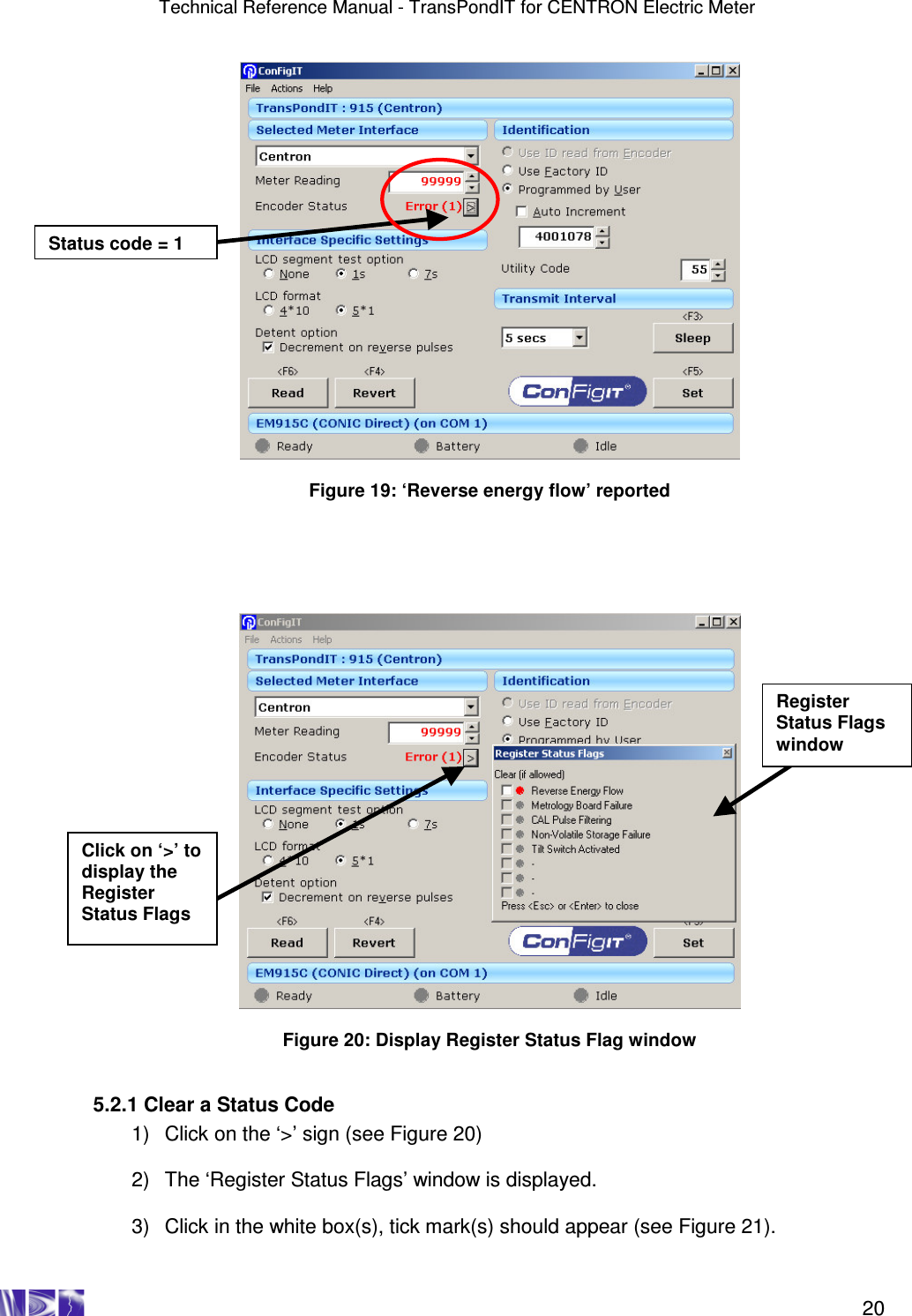
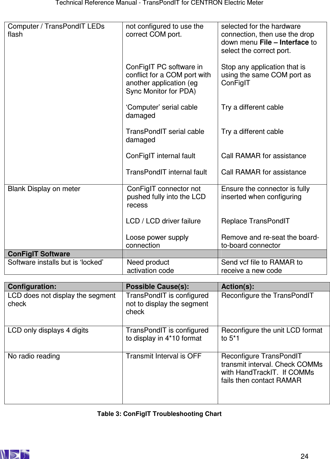
![Technical Reference Manual - TransPondIT for CENTRON Electric Meter 28 Figure C-2 Reverse meteorology board error Metrology Board Error [02] TransPondIT is operating correctly (i.e. LCD and radio readings are identical and non-zero) Follow utility procedures for swapping out meter base and fit TransPondIT to new meter Using ConFigIT clear the status code and check that TransPondIT is counting correctly. Refer to Chapters 3 and 5. Call RAMAR Technical Support 1-888-987-2627 END NO YES Note: If the LCD format is 4*10, then the radio reading will be 10x greater Confirm correct operation of the meter. (i.e. Meter reading increments. LCD reading and radio reading are as set by configuration). Note: If the LCD is configured for 4*10, then the radio reading will be 10x greater](https://usermanual.wiki/Blue-Tower-Communications/EM915CV1.Part-2/User-Guide-495804-Page-19.png)
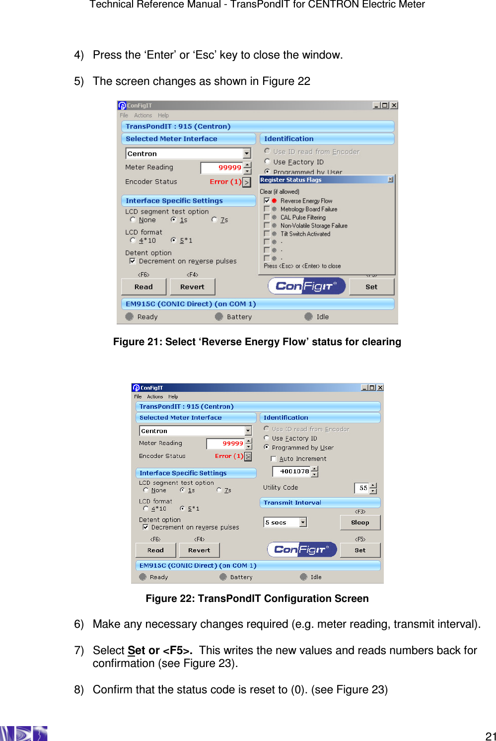
![Technical Reference Manual - TransPondIT for CENTRON Electric Meter 29 CAL Filtering [04] This status code is displayed when the TransPondIT records an instantaneous event of signals counted from the metrology board at a rate > 32 per second – this corresponds to >115kW . This is NOT a TransPondIT fault. It is for information purposes only. Report this event to the appropriate utility personnel. Refer to the CENTRON Meter Technical Reference Guide for more information on the meter.](https://usermanual.wiki/Blue-Tower-Communications/EM915CV1.Part-2/User-Guide-495804-Page-20.png)
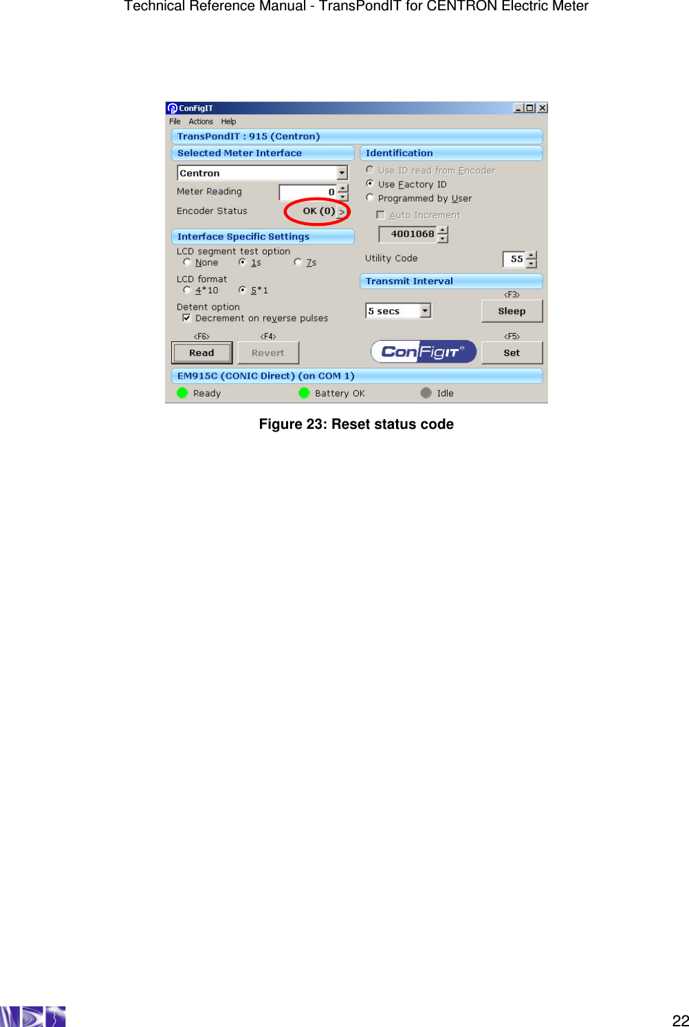
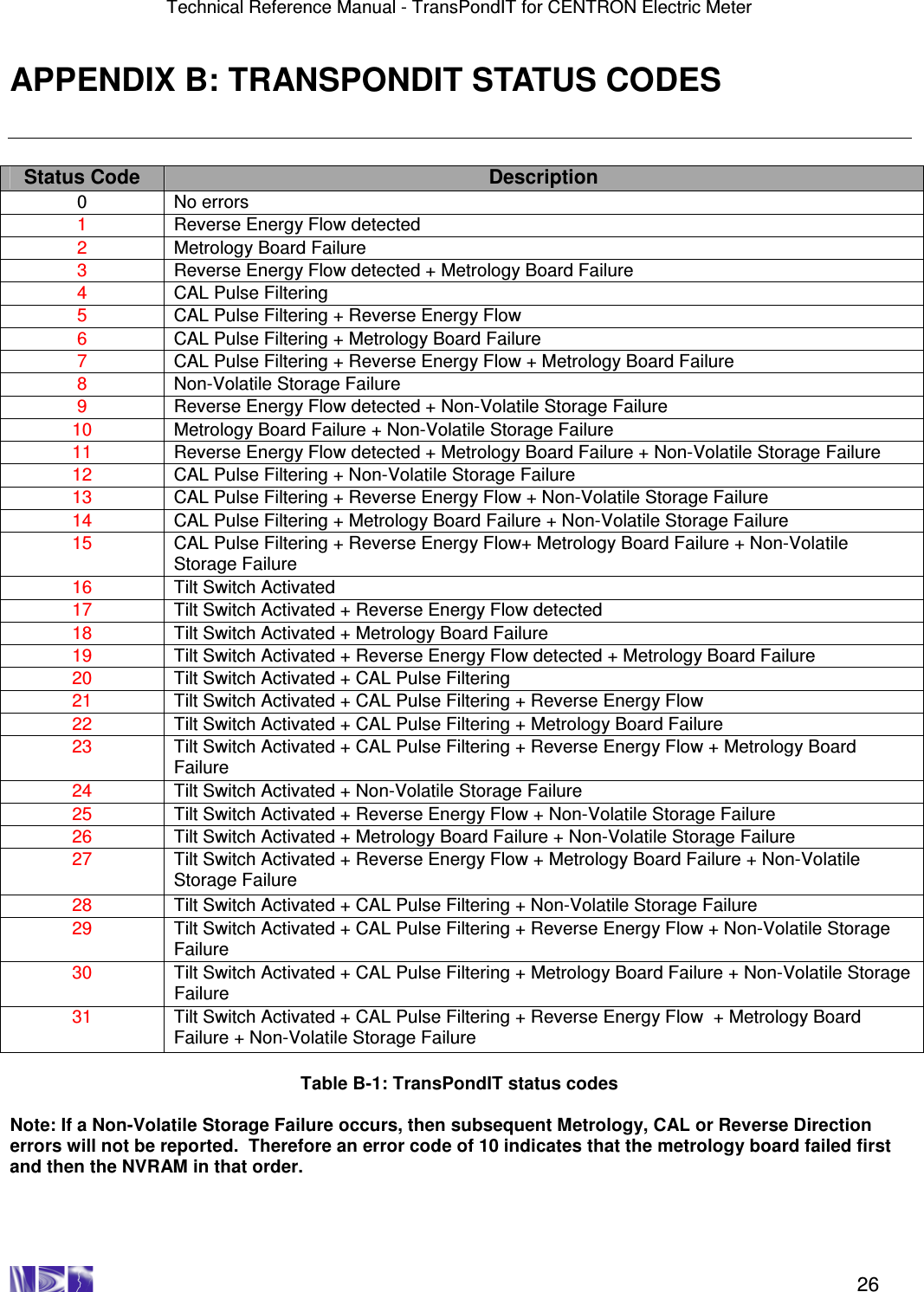
![Technical Reference Manual - TransPondIT for CENTRON Electric Meter 30 Figure C-3 NVRAM failure Call RAMAR Technical Support 1-888-987-2627 END Non Volatile Memory Fault [08] TransPondIT is faulty Replace Fit a new TransPondIT into the existing or new meter base. Configure the TransPondIT as required. (See chapters 3 & 5) Install new meter at customer site Return faulty TransPondIT to RAMAR Confirm correct operation of the meter. (i.e. Meter reading increments. LCD reading and radio reading are as set by configuration). Note: If the LCD is configured for 4*10, then the radio reading will be 10x greater](https://usermanual.wiki/Blue-Tower-Communications/EM915CV1.Part-2/User-Guide-495804-Page-21.png)
![Technical Reference Manual - TransPondIT for CENTRON Electric Meter 31 Tilt Switch Activated [16] Is the meter fitted upside down? Follow utility procedures for removing and re-fitting meter in the correct orientation. Report findings Using ConFigIT clear the status code and check that TransPondIT is counting correctly. Refer to chapters 3 & 5 END Is there any obvious physical damage? Report finding to appropriate utility personnel Call RAMAR Technical Support 1-888-987-2627 YES NO NO YES YES NO Figure C-4: Tilt switch Confirm correct operation of the meter. (i.e. Meter reading increments. LCD reading and radio reading are as set by configuration). Note: If the LCD is](https://usermanual.wiki/Blue-Tower-Communications/EM915CV1.Part-2/User-Guide-495804-Page-22.png)