Billion Electric BIL-8920AX Dual-lines VDSL2/ADSL2+ Wireless-AC 3G/4G LTE VPN Firewall Router User Manual 1 revised 0902

Billion Electric Co., Ltd. Dual-lines VDSL2/ADSL2+ Wireless-AC 3G/4G LTE VPN Firewall Router Users Manual 1 revised 0902
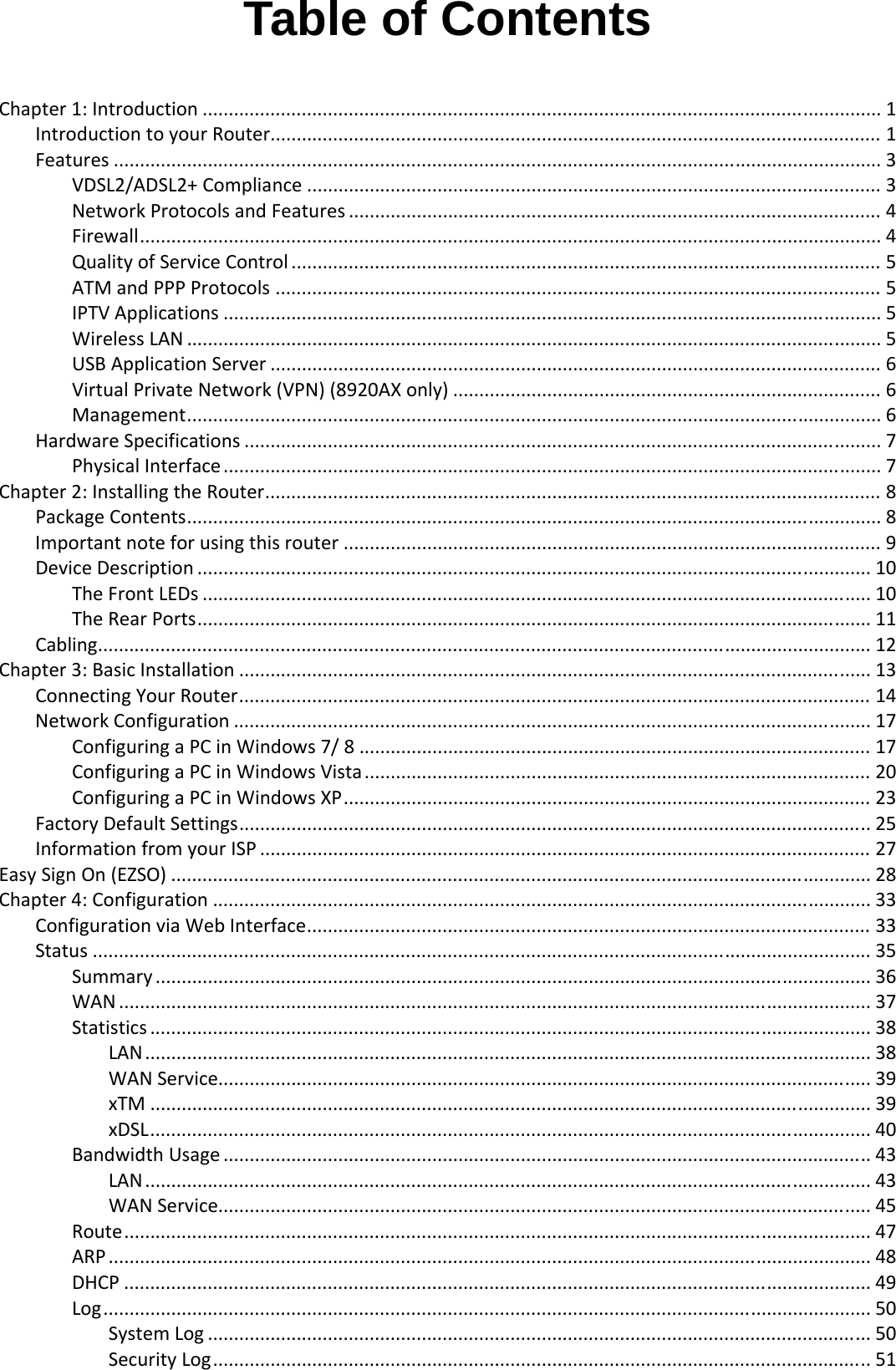
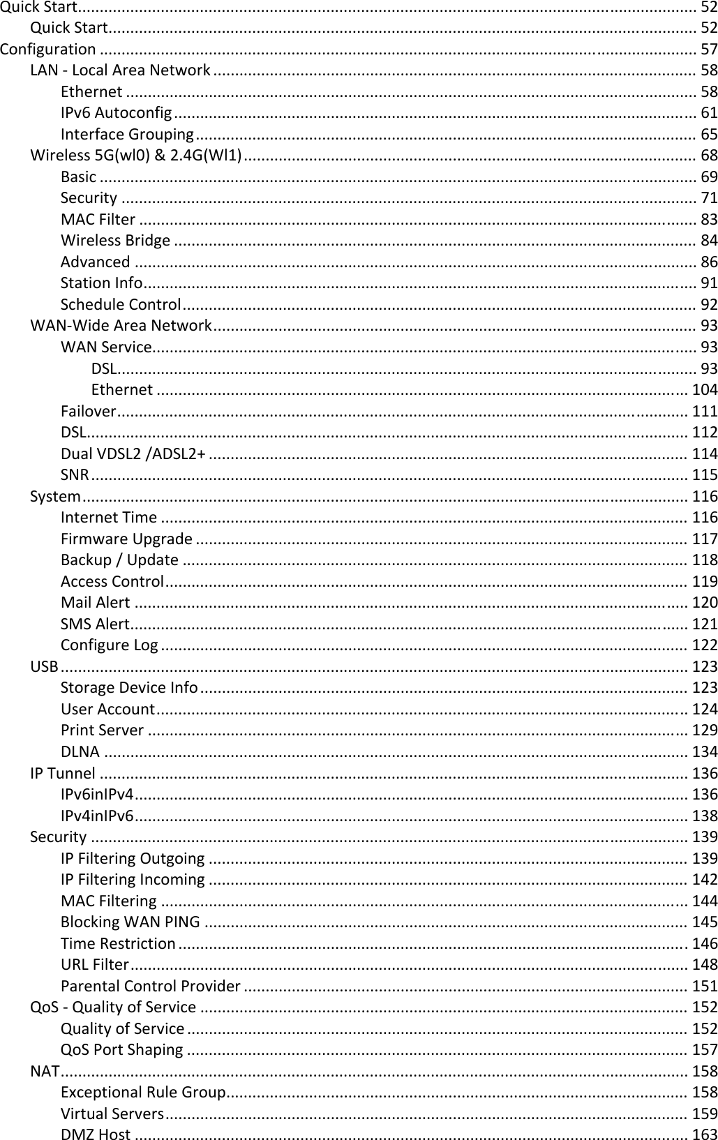
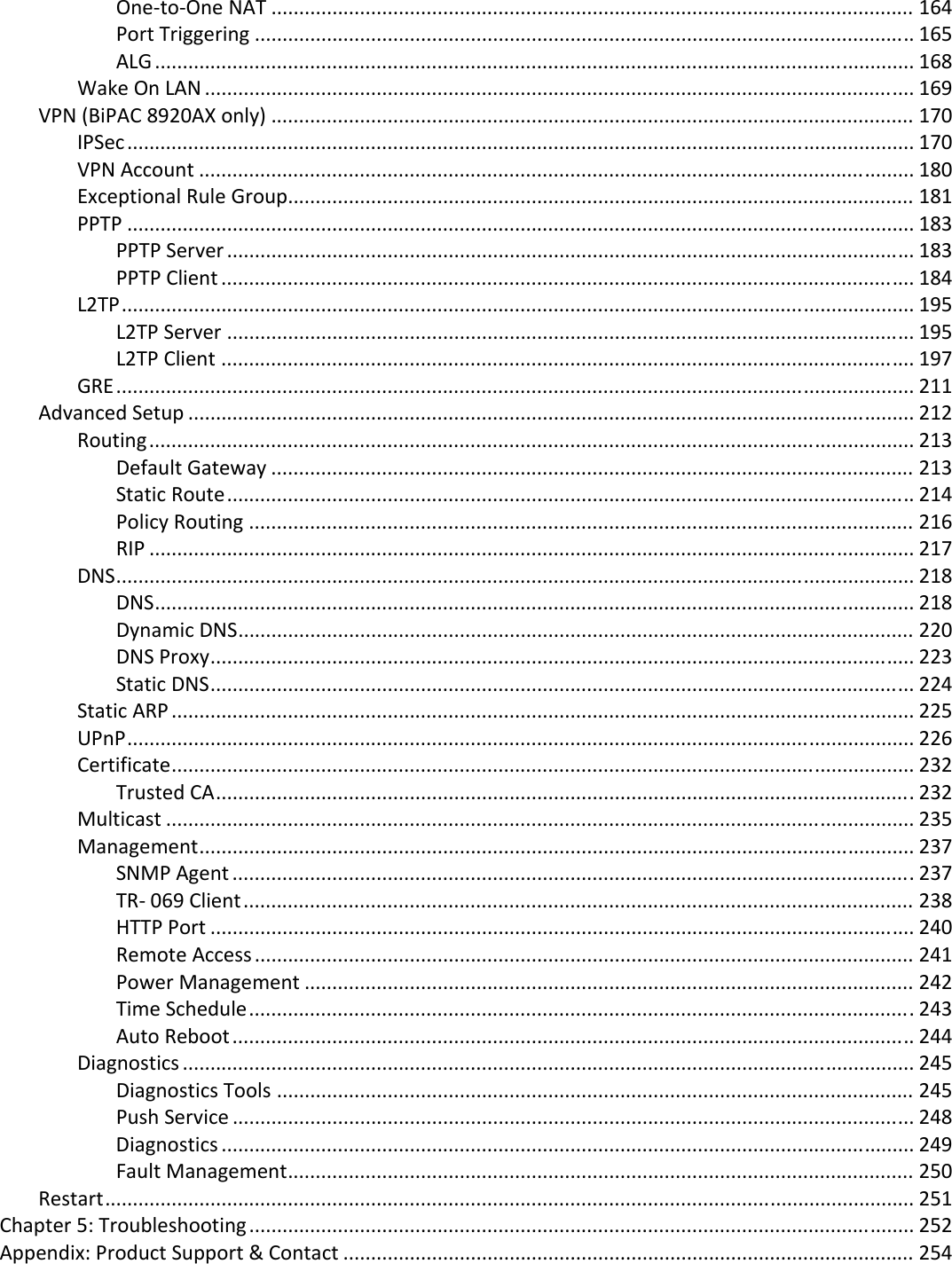
Contents

Users Manual-1-revised 0902

                   BiPAC 8920AX(L)       Dual-lines VDSL2/ADSL2+  Wireless-AC  (VPN) Firewall Router     User Manual                      Version Released: 2.50a.dl8  Last revised date:  September 1, 2015
Table of Contents  Chapter1:Introduction .................................................................................................................................. 1IntroductiontoyourRouter..................................................................................................................... 1Features ................................................................................................................................................... 3VDSL2/ADSL2+Compliance .............................................................................................................. 3NetworkProtocolsandFeatures ...................................................................................................... 4Firewall.............................................................................................................................................. 4QualityofServiceControl ................................................................................................................. 5ATMandPPPProtocols .................................................................................................................... 5IPTVApplications .............................................................................................................................. 5WirelessLAN ..................................................................................................................................... 5USBApplicationServer ..................................................................................................................... 6VirtualPrivateNetwork(VPN)(8920AXonly) .................................................................................. 6Management..................................................................................................................................... 6HardwareSpecifications .......................................................................................................................... 7PhysicalInterface.............................................................................................................................. 7Chapter2:InstallingtheRouter...................................................................................................................... 8PackageContents..................................................................................................................................... 8Importantnoteforusingthisrouter ....................................................................................................... 9DeviceDescription ................................................................................................................................. 10TheFrontLEDs ................................................................................................................................ 10TheRearPorts................................................................................................................................. 11Cabling.................................................................................................................................................... 12Chapter3:BasicInstallation ......................................................................................................................... 13ConnectingYourRouter......................................................................................................................... 14NetworkConfiguration .......................................................................................................................... 17ConfiguringaPCinWindows7/8 .................................................................................................. 17ConfiguringaPCinWindowsVista................................................................................................. 20ConfiguringaPCinWindowsXP..................................................................................................... 23FactoryDefaultSettings......................................................................................................................... 25InformationfromyourISP ..................................................................................................................... 27EasySignOn(EZSO) ...................................................................................................................................... 28Chapter4:Configuration .............................................................................................................................. 33ConfigurationviaWebInterface............................................................................................................ 33Status ..................................................................................................................................................... 35Summary ......................................................................................................................................... 36WAN ................................................................................................................................................ 37Statistics .......................................................................................................................................... 38LAN........................................................................................................................................... 38WANService............................................................................................................................. 39xTM .......................................................................................................................................... 39xDSL.......................................................................................................................................... 40BandwidthUsage ............................................................................................................................ 43LAN........................................................................................................................................... 43WANService............................................................................................................................. 45Route............................................................................................................................................... 47ARP.................................................................................................................................................. 48DHCP ............................................................................................................................................... 49Log................................................................................................................................................... 50SystemLog ............................................................................................................................... 50SecurityLog.............................................................................................................................. 51
QuickStart.............................................................................................................................................. 52QuickStart....................................................................................................................................... 52Configuration ......................................................................................................................................... 57LAN‐LocalAreaNetwork ............................................................................................................... 58Ethernet ................................................................................................................................... 58IPv6Autoconfig........................................................................................................................ 61InterfaceGrouping................................................................................................................... 65Wireless5G(wl0)&2.4G(Wl1)........................................................................................................ 68Basic ......................................................................................................................................... 69Security .................................................................................................................................... 71MACFilter ................................................................................................................................ 83WirelessBridge ........................................................................................................................ 84Advanced ................................................................................................................................. 86StationInfo............................................................................................................................... 91ScheduleControl...................................................................................................................... 92WAN‐WideAreaNetwork............................................................................................................... 93WANService............................................................................................................................. 93DSL..................................................................................................................................... 93Ethernet .......................................................................................................................... 104Failover................................................................................................................................... 111DSL.......................................................................................................................................... 112DualVDSL2/ADSL2+ .............................................................................................................. 114SNR......................................................................................................................................... 115System........................................................................................................................................... 116InternetTime ......................................................................................................................... 116FirmwareUpgrade ................................................................................................................. 117Backup/Update .................................................................................................................... 118AccessControl........................................................................................................................ 119MailAlert ............................................................................................................................... 120SMSAlert................................................................................................................................ 121ConfigureLog ......................................................................................................................... 122USB................................................................................................................................................ 123StorageDeviceInfo................................................................................................................ 123UserAccount.......................................................................................................................... 124PrintServer ............................................................................................................................ 129DLNA ...................................................................................................................................... 134IPTunnel ....................................................................................................................................... 136IPv6inIPv4............................................................................................................................... 136IPv4inIPv6............................................................................................................................... 138Security ......................................................................................................................................... 139IPFilteringOutgoing .............................................................................................................. 139IPFilteringIncoming .............................................................................................................. 142MACFiltering ......................................................................................................................... 144BlockingWANPING ............................................................................................................... 145TimeRestriction .....................................................................................................................146URLFilter................................................................................................................................ 148ParentalControlProvider ...................................................................................................... 151QoS‐QualityofService................................................................................................................ 152QualityofService ................................................................................................................... 152QoSPortShaping ................................................................................................................... 157NAT................................................................................................................................................ 158ExceptionalRuleGroup.......................................................................................................... 158VirtualServers........................................................................................................................ 159DMZHost ............................................................................................................................... 163
One‐to‐OneNAT .................................................................................................................... 164PortTriggering ....................................................................................................................... 165ALG ......................................................................................................................................... 168WakeOnLAN ................................................................................................................................ 169VPN(BiPAC8920AXonly) .................................................................................................................... 170IPSec.............................................................................................................................................. 170VPNAccount ................................................................................................................................. 180ExceptionalRuleGroup................................................................................................................. 181PPTP .............................................................................................................................................. 183PPTPServer ............................................................................................................................ 183PPTPClient ............................................................................................................................. 184L2TP............................................................................................................................................... 195L2TPServer ............................................................................................................................ 195L2TPClient ............................................................................................................................. 197GRE................................................................................................................................................ 211AdvancedSetup ................................................................................................................................... 212Routing.......................................................................................................................................... 213DefaultGateway .................................................................................................................... 213StaticRoute............................................................................................................................ 214PolicyRouting ........................................................................................................................ 216RIP .......................................................................................................................................... 217DNS................................................................................................................................................ 218DNS......................................................................................................................................... 218DynamicDNS.......................................................................................................................... 220DNSProxy............................................................................................................................... 223StaticDNS............................................................................................................................... 224StaticARP ...................................................................................................................................... 225UPnP.............................................................................................................................................. 226Certificate...................................................................................................................................... 232TrustedCA..............................................................................................................................232Multicast ....................................................................................................................................... 235Management................................................................................................................................. 237SNMPAgent ...........................................................................................................................237TR‐069Client......................................................................................................................... 238HTTPPort ............................................................................................................................... 240RemoteAccess ....................................................................................................................... 241PowerManagement .............................................................................................................. 242TimeSchedule........................................................................................................................243AutoReboot........................................................................................................................... 244Diagnostics .................................................................................................................................... 245DiagnosticsTools ................................................................................................................... 245PushService ........................................................................................................................... 248Diagnostics ............................................................................................................................. 249FaultManagement................................................................................................................. 250Restart.................................................................................................................................................. 251Chapter5:Troubleshooting ........................................................................................................................ 252Appendix:ProductSupport&Contact ....................................................................................................... 254 
1 Chapter 1: Introduction  Introduction to your Router The Billion BiPAC 8920AX(L) , a multi service VDSL2 Dual-lines (30a) Router over comparable single-port model. It features fibre-ready dual-WAN VDSL2 supports backward compatibility to ADSL2+ for a longer reach distance, an all-in-one advanced device including concurrent dual-band 802.11ac (5GHz) 1300Mbps and 802.11n (2.4GHz) 300Mbps, Gigabit Ethernet. As well as being IPv6-capable, the BiPAC 8920AX(L) VDSL2 router supports superfast fibre connections via a Gigabit Ethernet WAN port. It also has one USB port, allowing the device to act as a print server as well as a NAS (Network Attached Storage) device with DLNA (Digital Living Network Alliance) and FTP (File Transfer Protocol) access. With an array of advanced features, the Billion BiPAC 8920AX(L) delivers a future-proof solution for VDSL2 connections, superfast FTTC and ultra-speed FTTH (Fibre-To-The-Home) network deployment and services.    Flexible Deployment Options  The BiPAC 8920AX(L) provides users with flexible, scalable deployment options optimized to both reduce costs and provide the longest possible lifespan for the investment. The BiPAC8920AX(L) integrates dual WAN options; a VDSL2/ADSL2+ interface and a second 10/100/1000 Ethernet WAN interface which can be used for broadband connectivity to any other Ethernet broadband device. Operators can now deploy one device to support current and future network migration.   Maximum wireless performance  Featured with simultaneous dual-band technology, the BiPAC 8920AX(L) can run both 2.4GHz and 5GHz frequency bands at the same time, offering ultra-fast wireless speeds of up to 1600Mbps (1300+300 )and multiple SSIDs on both bands. The BiPAC 8920AX(L), by adopting this state-of-the-art technology, allows for multiple-demand applications, such as streaming HD videos and multiplayer gaming simultaneously. The Wireless Protected Access (WPA-PSK/WPA2-PSK) and Wireless Encryption Protocol (WEP) features enhance the level of transmission security and access control over wireless LAN. The router also supports the Wi-Fi Protected Setup (WPS) standard, allowing users to establish a secure wireless network by simply pushing a button. If your network requires wider coverage, the built-in Wireless Distribution System (WDS) repeater function allows you to expand your wireless network without the need for any external wires or cables.   Experience Gigabit The BiPAC 8920AX(L) has five Gigabit LAN ports and port #5 can be configured as an Ethernet WAN port. This EWAN offers another broadband connectivity option for connecting to a cable, DSL, fibre modem. The BiPAC8920AX(L) again offers users convenience and optimal network performance with data rates reaching up to 1Gbps.   IPv6 supported Internet Protocol version 6 (IPv6) is a version of the Internet Protocol that is designed to succeed IPv4. IPv6 has a vastly larger address space than IPv4. This results from the use of a 128-bit address, whereas IPv4 uses only 32 bits. The new address space thus supports 2128 (about 3.4×1038) addresses. This expansion provides flexibility in allocating addresses and routing traffic and eliminates the primary need for network address translation (NAT), which gained widespread deployment as an effort to alleviate IPv4 address exhaustion.
2 IPv6 also implements new features that simplify aspects of address assignment (stateless address autoconfiguration) and network renumbering (prefix and router announcements) when changing Internet connectivity providers. The IPv6 subnet size has been standardized by fixing the size of the host identifier portion of an address to 64 bits to facilitate an automatic mechanism for forming the host identifier from Link Layer media addressing information (MAC address). Network security is integrated into the design of the IPv6 architecture. Internet Protocol Security (IPsec) was originally developed for IPv6, but found widespread optional deployment first in IPv4 (into which it was back-engineered). The IPv6 specifications mandate IPsec implementation as a fundamental interoperability requirement.   Virtual AP A “Virtual Access Point” is a logical entity that exists within a physical Access Point (AP). When a single physical AP supports multiple “Virtual APs”, each Virtual AP appears to stations (STAs) to be an independent physical AP, even though only a single physical AP is present. For example, multiple Virtual APs might exist within a single physical AP, each advertising a distinct SSID and capability set. Alternatively, multiple Virtual APs might advertise the same SSID but a different capability set – allowing access to be provided via Web Portal, WEP, and WPA simultaneously. Where APs are shared by multiple providers, Virtual APs provide each provider with separate authentication and accounting data for their users, as well as diagnostic information, without sharing sensitive management traffic or data between providers. You can enable the virtual AP.    Web Based GUI It supports web based GUI for configuration and management. It is user-friendly and comes with online help. It also supports remote management capability for remote users to configure and manage this product.   Firmware Upgradeable  Device can be upgraded to the latest firmware through the WEB based GUI.
 3 Features  • Compliant with all ADSL2+/VDSL2 standards  • IPv6 ready (IPv4/IPv6 dual stack) • Dual- WAN approach – VDSL2/ADSL2+, and Ethernet WAN for Broadband Connectivity  • 5-port Gigabit Ethernet switch • 1-port (Port#5) Gigabit Ethernet WAN (EWAN) port for broadband connectivity. • Compliant with IEEE 802.11a/b/g/n/ac standards • Ultimate wireless speed 300+1300Mbps • WPS (Wi-Fi Protected Setup) for easy setup • Wireless security with WPA-PSK/WPA2-PSK • Supports WDS repeater function • Multiple wireless SSIDs with wireless guest access and client isolation • Secured IPSec VPN with powerful DES/ 3DES/ AES (BiPAC 8920AX only) • PPTP VPN with Pap/ Chap/ MS-CHAPv2 authentication (BiPAC 8920AX only) • Pure L2TP and L2TP over IPSec (BiPAC 8920AX only) • GRE tunnel (BiPAC 8920AX only) • SNR adjustments to achieve highest sync speeds • Monitoring of individual LAN/WAN traffic • Universal Plug and Play (UPnP) Compliance • QoS for traffic prioritization and bandwidth management • SOHO firewall security • Auto failover and failback • Supports IPTV application*2 • Ease of use with quick installation wizard (EZSO) • Broadcom chipset for better stability • Ideal for Home and SOHO users   VDSL2/ADSL2+ Compliance • Compliant with xDSL Standard - ITU-T G.993.2 (VDSL2) - ITU-T G.998.4 (G.inp) - ITU-T G.993.5 (G.vector) - ITU-T G.992.5 (G.dmt.bis plus, Annex M )  (ADSL2+ Annex M, available for BiPAC  8920AX(L)A model only) - ITU-T G.992.3 (G.dmt.bis, Annex M, ADSL2
 4 Annex M, available for BiPAC 8920AX(L)A model only) - Full-rate ANSI T1.413 Issue 2 - ITU-T G.992.1 (G.dmt) - ITU-T G.992.2 (G.lite) - ITU-T G.994.1 (G.hs) • Supports VDSL2 band plan: 997 and 998  • ADSL/2/2+ fallback modes • Supports VDSL2 profiles: 8a, 8b, 8c, 8d, 12a, 12b, 17a and 30a in single line mode  •  Supports ATM and PTM modes  Network Protocols and Features • IPv4 or IPv4 / IPv6 Dual Stack • NAT, static (v4/v6) routing and RIP-1 / 2 • IPv6 Stateless / Stateful Address Auto-configuration • IPv6 Router Advertisement • IPv6 over PPP • DHCPv6 • IP Tunnel IPv6 in IPv4(6RD) • IP Tunnel IPv4 in IPv6(DS-Lite) • Universal Plug and Play (UPnP) Compliant • Dynamic Domain Name System (DDNS) • Virtual Server, DMZ  • SNTP, DNS relay, IGMP snooping and IGMP proxy for video service • MLD snooping and MLD proxy for video service • Management based-on IP protocol, port number and address • Support port-based Interface Grouping (VLAN)  Firewall • Built-in NAT Firewall • Stateful Packet Inspection (SPI) • DoS attack prevention • Packet Filtering (v4/v6) - port, source IP address, destination IP address • MAC Filter • URL Content Filtering (v4/v6) – string or domain name detection in URL string • Remote access control for web base access • Packet filtering (v4/v6) - port, source IP address, destination IP address, MAC address • URL content filtering (v4/v6) - string or domain name detection in URL string
 5 • MAC filtering • Password protection for system management   Quality of Service Control • Supports the DiffServ approach •  Traffic prioritization and bandwidth management based-on IPv4/IPv6 protocol, port number and address  ATM and PPP Protocols • ATM Adaptation Layer Type 5 (AAL5) • Multiple Protocol over ALL5 (RFC 268, formerly RFC 1483) • Bridged or routed Ethernet encapsulation • VC and LLC based multiplexing • PPP over Ethernet (PPPoE) • PPP over ATM (RFC 2364) • Classical IP over ATM (RFC 1577) • MAC Encapsulated Routing (RFC 1483 MER) • OAM F4 / F5  IPTV Applications*2 • IGMP Snooping and IGMP Proxy • MLD Snooping and MLD Proxy • Interface Grouping (VLAN) • Quality of Service (QoS)  • VLAN MUX support   Wireless LAN • Compliant with IEEE 802.11 a/ b/ g/ n/ac standards • 2.4 GHz and 5GHz frequency range  • Up to 300+1300 Mbps wireless operation rate • 64 / 128 bits WEP supported for encryption • WPS (Wi-Fi Protected Setup) for easy setup • Supports WPS v2 • Wireless Security with WPA-PSK / WPA2-PSK support • Multiple wireless SSIDs with wireless guest access and client isolation • WDS repeater function support • Wireless LAN Schedule control
 6   USB Application Server • Storage/NAS: FTP server, Samba server,DLNA • Printer Server   Virtual Private Network (VPN) (8920AX only) • IKE key management • DES, 3DES and AES encryption for IPSec  • L2TP over IPSec • Pap/ Chap/ MS-CHAPv2 authentication for PPTP • IPSec pass-through • GRE tunnel  Management • Easy Sign-on (EZSO) • Web-based GUI for remote and local management (IPv4/IPv6) • Firmware upgrades and configuration data upload and download via web-based GUI • Embedded Telnet server for remote and local management • Supports DHCP server / client / relay • Supports SNMP v1,v2, MIB-I and MIB-II  • TR-069*1 supports remote management • Available Syslog • Mail alert for WAN IP changed • Auto failover and fallback • Push Service for diagnostics and debug usage    1. On request for Telco / ISP projects 2. IPTV application may require subscription to IPTV services from a Telco / ISP. 3. Specifications on this datasheet are subject to change without prior notice.
 7 Hardware Specifications  Physical Interface • WLAN: 3 external antennas • DSL: VDSL port • USB 2.0: 1-port USB 2.0 interface for storage service and printer server  • Ethernet: 5-port 10 / 100 / 1000Mbps auto-crossover (MDI / MDI-X) Switch •  EWAN: 1 Gigabit Ethernet port (port#5) connecting directly to Fiber/ xDSL/ Cable modem, also serving as a Ethernet port#5 when not in EWAN use • Wireless on/off  and WPS push button • Power jack • Power switch • Factory default reset button
 8 Chapter 2: Installing the Router  Package Contents  • BiPAC 8920AX(L) Dual-lines VDSL2/ADSL2+ Wireless-AC (VPN) Firewall Router • Quick Start Guide • CD containing the on-line manual • Vertical Stand • RJ-45 Cat. 5e STP Ethernet cable • RJ-11 telephone cable • Power adapter • Splitter / Micro-filter (Optional)
 9  Important note for using this router     Warning 1. Do not use the router in high humidity or high temperatures. 2. Do not use the same power source for the router as other equipment. 3. Do not open or repair the case yourself. If the router is too hot, turn off the power immediately and have it repaired at a qualified service center. 4. Avoid using this product and all accessories outdoors.     Attention 1. Place the router on a stable surface. 2. Only use the power adapter that comes with the package. Using a different voltage rating power adapter may damage the router.
 10 Device Description   The Front LEDs     LED  Status  Meaning Red  Boot failure or in emergency mode Power Green  System ready Green  Connected to an Gigabit Ethernet device or to a broadband connection device. Orange  Connect to an 10/100Mbps Ethernet device Gigabit Ethernet Port 5/EWAN Blinking  Data being transmitted / received Green  Successfully connected to a 1000Mbos LAN device  Orange  Successfully connected to a 10/100Mbos LAN device Gigabit Ethernet Port 1-4 Blinking  Data being transmitted / received USB  Green   USB connection established Green   Wireless connection established Wireless  Blinking   Data being transmitted / received Green   Wireless device(s) being connected successfully via WPS mode Blinking  WPS configuration being in progress WPS Off  WPS is off Green  Successfully connected to an xDSL DSLAM (Line Synced) Green Blinking  DSL synchronizing or waiting for DSL synchronizing DSL 1 /2 Off  DSL cable unplugged  Green  IP connected and traffic is passing through the device Blinking  Data being transmitted / received Red  BiPAC 8920AX(L) fails to obtain and IP. Internet Off  BiPAC 8920AX(L) is either in bridged mode or WAN/DSL connection is not ready
 11 The Rear Ports      Port  Meaning 1  ON/OFF  Power ON / OFF switch. 2   PWR  Connect the supplied power adapter to this jack.  3  WPS /Wireless on/off button By controlling the pressing time, users can achieve two different effects:  (1) WPS: Press &hold the button for less than 6 seconds to trigger WPS function.  (2) Wireless ON/OFF button: Press & hold the button for more than 6 seconds to On/Off the wireless. 4 Reset Push and hold the reset button for five (5) seconds to restore to its factory default settings (this is used when you cannot login to the router, e.g. forgot your password) 5  E (Gb EWAN) Connect to Fiber/ Cable/ xDSL Modem with a RJ-45 cable, for broadband connectivity.  Note: LAN 5 automatically becomes an EWAN port when EWAN internet interface is being selected in the GUI 6  GB LAN Ethernet (1-5) Connect PCs, Laptops or any other office/home LAN devices with the supplied RJ-45 Ethernet cable (Cat-5 or Cat-5e) to any of the five LAN ports.  Note: Port 5 is a LAN / WAN Configurable Port. 7 USB  Connect with a hard driver for mobile connectivity. 8  DSL  Connect the device to an ADSL/VDSL telephone jack or splitter using a RJ-11 telephone cable / Y-Cable for xDSL Dual-lines       1234568 7
 12 Cabling  One of the most common causes of problems is bad cabling or ADSL line(s). Make sure that all connected devices are turned on. On the front panel of your router is a bank of LEDs. Verify that the LAN Link and ADSL line LEDs are all lit. If they are not, verify if you are using the proper cables. If the error persists, you may have a hardware problem. In this case, you should contact technical support.  Make sure you have a line filter with all devices (e.g. telephones, fax machines, analogue modems) connected to the same telephone line and the wall socket (unless you are using a Central Splitter or Central Filter installed by a qualified and licensed electrician), and ensure that all line filters are correctly installed and the right way around. Missing line filters or line filters installed the wrong way around can cause problems with your ADSL connection, including causing frequent disconnections. If you have a back-to-base alarm system you should contact your security provider for a technician to make any necessary changes.
 13 Chapter 3: Basic Installation   The router can be configured through your web browser. A web browser is included as a standard application in the following operating systems: Linux, Mac OS / Windows 8, Windows 7 / 98 / NT / 2000 / XP / Me / Vista, etc. The product provides an easy and user-friendly interface for configuration.   Please check your PC network components. The TCP/IP protocol stack and Ethernet network adapter must be installed. If not, please refer to your Windows-related or other operating system manuals.  There are ways to connect the router, either through an external repeater hub or connect directly to your PCs. However, make sure that your PCs have an Ethernet interface installed properly prior to connecting the router device. You ought to configure your PCs to obtain an IP address through a DHCP server or a fixed IP address that must be in the same subnet as the router. The default IP address of the router is 192.168.1.254 and the subnet mask is 255.255.255.0 (i.e. any attached PC must be in the same subnet, and have an IP address in the range of 192.168.1.1 to 192.168.1.253). The best and easiest way is to configure the PC to get an IP address automatically from the router using DHCP. If you encounter any problem accessing the router web interface it is advisable to uninstall your firewall program on your PCs, as they can cause problems accessing the IP address of the router. Users should make their own decisions on what is best to protect their network.  Please follow the following steps to configure your PC network environment.    Any TCP/IP capable workstation can be used to communicate with or through this router. To configure other types of workstations, please consult your manufacturer documentation.
 14 Connecting Your Router  Users can connect the ADSL2+ router as the following.   DSL Router mode:  - Single Pair
 15 - two-paired
 16 Broadband Router mode:
 17   Network Configuration  Configuring a PC in Windows 7/ 8                   1. Go to Start. Click on Control Panel. Then click on Network and Internet. 2. When the Network and Sharing Center window pops up, select and click on Change adapter settings on the left window panel. 3. Select  the  Local Area Connection, and right click the icon to select Properties.
 18   IPv4:     4. Select  Internet Protocol Version 4 (TCP/IPv4) then click Properties  5. In the TCP/IPv4 properties window, select the Obtain an IP address automatically and Obtain DNS Server address automatically radio buttons. Then click OK to exit the setting.  6. Click OK again in the Local Area Connection Properties window to apply the new configuration.
 19   IPv6:      4. Select  Internet Protocol Version 6 (TCP/IPv6) then click Properties     5. In the TCP/IPv6 properties window, select the Obtain an IPv6 address automatically and  Obtain DNS Server address automatically radio buttons. Then click OK to exit the setting.  6. Click OK again in the Local Area Connection Properties window to apply the new configuration.
 20  Configuring a PC in Windows Vista  1. Go to Start. Click on Network.  2. Then click on Network and Sharing Center at the top bar. 3. When the Network and Sharing Center window pops up, select and click on Manage network connections on the left window pane. 4. Select  the  Local Area Connection, and right click the icon to select Properties.
 21 IPv4:      5. Select  Internet Protocol Version 4 (TCP/IPv4) then click Properties.  6. In  the  TCP/IPv4 properties window, select the Obtain an IP address automatically and Obtain DNS Server address automatically radio buttons. Then click OK to exit the setting.  7. Click OK again in the Local Area Connection Properties window to apply the new configuration.
 22 IPv6:          8. Select  Internet Protocol Version 6 (TCP/IPv6) then click Properties.  9. In  the  TCP/IPv6 properties window, select the Obtain an IPv6 address automatically and Obtain DNS Server address automatically radio buttons. Then click OK to exit the setting.  10. Click OK again in the Local Area Connection Properties window to apply the new configuration.
 23 Configuring a PC in Windows XP     IPv4:  1.  Go to Start / Control Panel (in Classic View). In the Control Panel, double-click on Network Connections 2.  Double-click Local Area Connection.  3.  In the Local Area Connection Status window, click Properties. 4.  Select  Internet Protocol (TCP/IP) and click Properties.  5.  Select the Obtain an IP address automatically  and the  Obtain DNS server address automatically radio buttons.  6.  Click OK to finish the configuration.
 24 IPv6:  IPv6 is supported by Windows XP, but you should install it first. Act as shown below: 1. On the desktop, Click Start > Run, type cmd, then press Enter key in the keyboard, the following screen appears.   2. Key in command ipv6 install    Configuration is OK now, you can test whether it works ok.
 25 Factory Default Settings  Before configuring your router, you need to know the following default settings.   Web Interface (Username and Password)  Three user levels are provided by this router, namely Administrator,  Remote and Local respectively. See Access Control .   Administrator     Username: admin    Password: admin   Local     Username: user    Password: user   Remote      Username: support    Password: support    Attention If you have forgotten the username and/or password of the router, you can restore the device to its default setting by pressing the Reset Button more than 5 seconds.   Device LAN IPv4 settings     IPv4 Address: 192.168.1.254    Subnet Mask: 255.255.255.0   Device LAN IPv6 settings     IPv6 Address / prefix: Default is a link-local address and is different from each other as MAC address is different from one to one. For example: fe80:0000:0000:0000:0204:edff:fe01:0001 / 64, the prefix initiates by fe80::   DHCP server for IPv4     DHCP server is enabled.    Start IP Address: 192.168.1.254    IP pool counts: 100
 26 LAN and WAN Port Addresses The parameters of LAN and WAN ports are pre-set in the factory.  The default values are shown in the table.  IPv4  LAN Port WAN Port IPv4 address 192.168.1.254 Subnet Mask 255.255.255.0 DHCP server function Enabled  IP addresses for distribution to PCs 100 IP addresses continuing from 192.168.1.100 through 192.168.1.199   The PPPoE function is enabled to automatically get the WAN port configuration from the ISP.   IPv6  LAN Port WAN Port IPv6 address/prefix  Default is a link-local address and is different from each other as MAC address is different from one to one.For example :fe80::204:edff:fe01:1/64,  the prefix initiates by fe80:: DHCP server function Enabled   The PPPoE function is enabled to automatically get the WAN port configuration from the ISP.
 27 Information from your ISP   Before configuring this device, you have to check with your ISP (Internet Service Provider) to find out what kind of service is provided.  Gather the information as illustrated in the following table and keep it for reference.  PPPoE(RFC2516)   VPI/VCI, VC / LLC-based multiplexing, Username, Password, Service Name, and Domain Name System (DNS) IP address (it can be automatically assigned by your ISP when you connect or be set manually). PPPoA(RFC2364)   VPI/VCI, VC / LLC-based multiplexing, Username, Password and Domain Name System (DNS) IP address (it can be automatically assigned by your ISP when you connect or be set manually). DHCP Client VPI/VCI, VC / LLC-based multiplexing, Domain Name System (DNS) IPaddress (it can be automatically assigned by your ISP when you connect or be set manually). IPoA(RFC1577)  VPI/VCI, VC / LLC-based multiplexing, IP address, Subnet mask, Gateway address, and Domain Name System (DNS) IP address (it is a fixed IP address). Pure Bridge   VPI/VCI, VC / LLC-based multiplexing to use Bridged Mode.
 28 Easy Sign On (EZSO)  This special feature makes it easier for you to configure your router so that you can connect to the internet in a matter of seconds without having to logon to the router GUI for any detail configuration. This configuration method is usually auto initiated if user is to connect to the internet via Billion's router for the first time.  After setting up the router with all the appropriate cables plugged-in, open up your IE browser, the EZSO WEB GUI will automatically pop up and request that you enter some basic information that you have obtained from your ISP. By following the instructions given carefully and through the information you provide, the router will be configured in no time and you will find yourself surfing the internet sooner than you realize.  EZSO window pops up: Step1: Set the administration password.   Step 2: Set the Time Zone.   Step 3: Configure the WAN interface.  DSL mode (ADSL mode, please choose ATM; VDSL, please choose PTM) Here take ADSL for example. Before configuring with DSL mode, please confirm you have correctly connected the DSL line, and it is now synchronized.  Select DSL, press Continue to go on to next step, press “Done” to quit the setting.  1. Enter the username, password from your ISP, for IP and DNS settings; also refer to your ISP. Here IPv6 service is enabled by default.
 29   If the DLS line doesn’t synchronize, the page will pop up warning of the DSL connection failure.   3. Wait while the device is configured (DSL synchronized).   4. WAN port configuration is success and next to wireless, if you want skip wireless setting, click Done.   Click Done, web configuration will be loaded, you will enter the web configuration page.    5. After the configuration is successful, click Next to Wireless button and you may proceed to configure the Wireless setting. The 8920AX(L) supports dual-band wireless, here you can set to activate wireless on which band or both and set the SSID and encryption Key. (1. Leave it empty to disable the wireless security; 2. Fill in the Key, and the encryption mode will be WPA2-PSK/AES).
 30    6. Continue to set 2.4GHz wireless.    7. Success in configuring the EZSO.
 31 Ethernet mode 1. Select Ethernet, press Continue to go on to next step.   2.  Enter the username, password from your ISP, for IP and DNS settings, also refer to your ISP. Here IPv6 service is enabled by default.    3. Wait while the device is configured.   4. WAN port configuration is success.   Click Done, web configuration will be loaded, you will enter the web configuration page.
 32 5. After the configuration is successful, click Next to Wireless button and you may proceed to configure the Wireless setting. The 8920AX(L) supports dual-band wireless, here you can set to activate wireless on which band or both and set the SSID and encryption Key (1. Leave it empty to disable the wireless security; 2. Fill in the Key, and the encryption mode will be WPA2-PSK/AES).    6. Continue to set 2.4GHz wireless.    7.  Success in configuring the EZSO.
 33  Chapter 4: Configuration  Configuration via Web Interface  Open your web browser; enter the IP address of your router, which by default is 192.168.1.254, and click   or press ‘Enter’ key on the keyboard, a login prompt window will appear. The default root username and password are “admin” and “admin” respectively.        Congratulations! You are now successfully logged in to the VDSL2+ Router!
 34 Once you have logged on to your BiPAC 8920AX(L) Router via your web browser, you can begin to set it up according to your requirements. On the configuration homepage, the left navigation pane links you directly to the setup pages, which include:    Status (Summary, WAN, Statistics, Bandwidth Usage, Route, ARP, DHCP, Log,)  Quick Start (Quick Start)  Configuration (LAN, Wireless 2.4G(wl0), Wireless 5G(wl1), WAN, System, USB, IP Tunnel, Security, Quality of Service, NAT, Wake On LAN)  VPN (IPSec, VPN Account, Exceptional Rule Group, PPTP, L2TP, GRE)  Advanced  Setup  (Routing, DNS, Static ARP, UPnP, Certificate, Multicast, Management, Diagnostics)
 35 Status  This Section gives users an easy access to the information about the working router and access to view the current status of the router. Here Summary, WAN, Statistics, Bandwidth Usage, Route, ARP, DHCP , and Log subsections are included.
 36 Summary  The basic information about the device is provided here (the following is a configured screenshots to let users understand clearly).    Device Information Model Name: Displays the model name. Host Name: Displays the name of the router. System Up-Time: Displays the elapsed time since the device is on. Date/Time: Displays the current exact date and time. Sync button is to synchronize the Date/Time with your PC time without regard to connecting to internet or not. Software Version: Firmware version.  LAN IPv4 Address: Displays the LAN IPv4 address. LAN IPv6 Address: Displays the LAN IPv6 address. Default is a Link-Local address, but when connects to ISP, it will display the Global Address, like above figure. MAC Address: Displays the MAC address. DSL PHY and Driver Version: Display DSL PHY and Driver version. Wireless Driver Version: Displays wireless driver version.   WAN Line Rate – Upstream (Kbps): Displays Upstream line Rate in Kbps. Line Rate – Downstream (Kbps): Displays Downstream line Rate in Kbps. Default Gateway/IPv4 Address: Display Default Gateway and the IPv4 address. Connection Time: Displays the elapsed time since ADSL connection is up. Primary DNS Server: Displays IPV4 address of Primary DNS Server. Secondary DNS Server: Displays IPV4 address of Secondary DNS Server. Default IPv6 Gateway/IPv6 Address: Display the IPv6 Gateway and the obtained IPv6 address.
 37 WAN  This table displays the information of the WAN connections, users can turn here for WAN connection information.   Interface: The WAN connection interface.  Description: The description of this connection. Type: The protocol used by this connection.  Status: To disconnect or connect the link. Connection Time: The WAN connection time since WAN is up. IPv4 Address: The WAN IPv4 Address the device obtained. IPv6 Address: The WAN IPv6 Address the device obtained. DNS: The DNS address the device obtained.
 38 Statistics  LAN The table shows the statistics of LAN.  Note: P5 can be configured as EWAN, and when the device is in EWAN profile, there is no P5/EWAN interface as P5 is working as a WAN port.  (DSL)   (EWAN) Interface: List each LAN interface. P1-P4 indicates the four LAN interfaces. Bytes: Display the Received and Transmitted traffic statistics in Bytes. Packets: Display the Received and Transmitted traffic statistics in Packets. Errors: Display the statistics of errors arising in Receiving or Transmitting data. Drops: Display the statistics of drops arising in Receiving or Transmitting data.   Reset: Press this button to refresh the statistics.
 39 WAN Service The table shows the statistics of WAN.    Interface: Display the connection interface. Description: the description for the connection. Bytes: Display the WAN Received and Transmitted traffic statistics in Bytes. Packets: Display the WAN Received and Transmitted traffic statistics in Packests. Errors: Display the statistics of errors arising in Receiving or Transmitting data. Drops: Display the statistics of drops arising in Receiving or Transmitting data.   Reset: Press this button to refresh the statistics.  xTM The Statistics-xTM screen displays all the xTM statistics   Port Number: Shows number of the port for xTM. In Octets: Number of received octets over the interface. Out Octets: Number of transmitted octets over the interface. In Packets: Number of received packets over the interface. Out Packets: Number of transmitted packets over the interface. In OAM Cells: Number of OAM cells received. Out OAM Cells: Number of OAM cells transmitted. In ASM Cells: Number of ASM cells received. Out ASM Cells: Number of ASM cells transmitted. In Packet Errors: Number of received packets with errors. In Cell Errors: Number of received cells with errors. Reset: Click to reset the statistics.
 40  xDSL    Mode: Modulation protocol, including G.dmt, G.lite, T1.413, ADSL2, AnnexL, ADSL2+ and AnnexM. Traffic Type: Transfer mode, here supports ATM and PTM. Status: Show the status of DSL link.
 41 Link Power State: Show link output power state. Line Coding (Trellis): Trellis on/off. SNR Margin (dB): Show the Signal to Noise Ratio(SNR) margin. Attenuation (dB): This is estimate of average loop attenuation of signal. Output Power (dBm): Show the output power. Attainable Rate (Kbps): The sync rate you would obtain. Rate (Kbps): Show the downstream and upstream rate in Kbps. MSGc (#of bytes in overhead channel message): The number of bytes in overhead channel message. B (# of bytes in Mux Data Frame): The number of bytes in Mux Data frame. M (# of Mux Data Frames in FEC Data Frame): The number of Mux Data frames in FEC frame. T (Mux Data Frames over sync bytes): The number of Mux Data frames over all the sync bytes. R (# of check bytes in FEC Data Frame): The number of check bytes in FEC frame. S (ratio of FEC over PMD Data Frame length): The ratio of FEC over PMD Data frame length L (# of bits in PMD Data Frame): The number of bit in PMD Data frame D (interleaver depth): Show the interleaver depth. Delay (msec): Show the delay time in msec.  INP (DMT symbol): Show the DMT symbol. Super Frames: The total number of super frames. Super Frame Errors: the total number of super frame errors. RS Words: Total number of Reed-Solomon code errors. RS Correctable Errors: Total number of RS with correctable errors. RS Uncorrectable Errors: Total number of RS words with uncorrectable errors. HEC Errors: Total number of Header Error Checksum errors. OCD Errors: Total number of out-of-cell Delineation errors. LCD Errors: Total number of Loss of Cell Delineation. Total Cells: Total number of cells. Data Cells: Total number of data cells. Bit Errors: Total number of bit errors. Total ES: Total Number of Errored Seconds. Total SES: Total Number of Severely Errored Seconds. Total UAS: Total Number of Unavailable Seconds. xDSL BER Test: Click this button to start a bit Error Rate Test. The ADSL Bit Error Rate (BER) test determines the quality of the ADSL connection. The test is done by transferring idle cells containing a known pattern and comparing the received data with this known pattern to check for any errors.
 42  Select the Tested Time(sec), press Start to start test.    When it is OK, the following test result window will appear. You can view the quality of ADSL connection. Here the connection is OK.  Reset: Click this button to reset the statistics.
 43 Bandwidth Usage Bandwidth Usage provides users direct view of bandwidth usage with simple diagram. Bandwidth usage shows the use of the bandwidth from two angles: Transmitted and Received, giving users a clear idea of the usage.  LAN Note: P5 can be configured as EWAN, and when the device is in EWAN profile, there is no P5/EWAN interface as P5 is working as a WAN port.  (EWAN)  Press View LAN Transmitted button to change the diagram to the statistics from a Received Bytes of view. (Note:  means Ethernet port #1, and the traffic information of the port #1 is identified with green, the same color with eth1 in the diagram; other ports all take the same mechanism.)
 44 When you press View WAN Traffic concurrently button, the WAN Bandwidth Usage pops up so that users can view the WAN traffic concurrently.
 45 WAN Service   Press View WAN Transmitted button to change the diagram to the statistics from a Received Bytes of view.
 46 Press View LAN Traffic concurrently button to directly switch to the LAN Bandwidth Usage page to view the LAN traffic concurrently.
 47 Route    Destination: The IP address of destination network. Gateway: The IP address of the gateway this route uses. Subnet Mask: The destination subnet mask. Flag: Show the status of the route.  U: Show the route is activated or enabled.  H (host): destination is host not the subnet.  G: Show that the outside gateway is needed to forward packets in this route.  R: Show that the route is reinstated from dynamic routing.   D:  Show that the route is dynamically installed by daemon or redirecting.  M: Show the route is modified from routing daemon or redirect. Metric: Display the number of hops counted as the Metric of the route. Service: Display the service that this route uses. Interface: Display the existing interface this route uses.
 48 ARP  This section displays the router’s ARP (Address Resolution Protocol) Table, which shows the mapping of Internet (IP) addresses to Ethernet (MAC) addresses. This is useful as a quick way of determining the MAC address of the network interface of your PCs to use with the router’s Security –  MAC Filtering function. Here IPv6 Neighbor Table, listed with IPv6 address-MAC mapping, is supported.    ARP table IP Address: Shows the IP Address of the device that the MAC address maps to. Flag: Shows the current status of the ARP entries.   Complete: the route resolving is processing well.   M(Marked as permanent entry): the route is permanent.   P (publish entry): publish this route item. MAC Address: Shows the MAC address that is corresponded to the IP address of the device it is mapped to. Device: here refers to the physical interface, it is a concept to identify Clients from LAN or WAN. For example, the Clients in LAN, here displays “br0”. Mark: Show clearly the SSID (WLAN) the device is in.   Neighbor Cache Table  IPv6 address: Shows the IPv6 Address of the device that the MAC address maps to. MAC Address: Shows the MAC address that is corresponded to the IPv6 address of the device it is mapped to. Device: here refers to the physical interface, it is a concept to identify Clients from LAN or WAN. For example, the Clients in LAN, here displays “br0”. Mark: Show clearly the SSID (WLAN) the device is in.
 49 DHCP   The DHCP Table lists the DHCP lease information for all IP addresses assigned by the DHCP server in the device.    Host Name: The Host Name of DHCP client. MAC Address: The MAC Address of internal DHCP client host. IP Address: The IP address which is assigned to the host with this MAC address. Expires in: Show the remaining time after registration.  Mark: Show clearly the SSID (WLAN) the device is in.
 50 Log  System Log Display system logs accumulated up to the present time. You can trace historical information with this function. And the log policy can be configured in Configure Log section.   Refresh: Click to update the system log. Clear: Click to clear the current log from the screen.
 51 Security Log Security log displays the message logged about security, like filter messages and some firewall message. You can turn to IP Filtering Outgoing, IP Filtering Incoming, URL Filter to determine if you want to log this information. Also you can turn to Configure Log section below to determine the level to log the message. You can use this to track potential threats to your system and network.  Refresh: Click to update the system log. Clear: Click to clear the current log from the screen.
 52 Quick Start  Quick Start  This part allows you to quickly configure and connect your router to internet.  DSL mode (ADSL mode, please choose ATM; VDSL, please choose PTM) Here take ADSL for example.  Select DSL, press Continue to go on to next step. Enter the username, password from your ISP, for IP and DNS settings; also refer to your ISP. Here IPv6 service is enabled by default.   If the DLS line is not synchronized, the page will pop up warning of the DSL connection failure.
 53 3. Wait while the device is configured.   4. WAN port configuration is successful.   5. After the configuration is successful, click Next to Wireless button and you may proceed to configure the Wireless setting. The 8920AX(L)  supports dual-band wireless, here you can set to activate wireless on which band or both and set the SSID and encryption Key (1. Leave it empty to disable the wireless security; 2. Fill in the Key, and the encryption mode will be WPA2-PSK/AES).    6. Continue to set 2.4GHz wireless.    7. Success.
 54  Go back to Status > Summary for more information.
 55 Ethernet mode 1. Select Ethernet, press Continue to go on to next step.   2.  Enter the username, password from your ISP, for IP and DNS settings; also refer to your ISP. Here IPv6 service is enabled by default.    3. Wait while the device is configured.   4. WAN port configuration is successful.
 56  5. After the configuration is successful, click Next to Wireless button and you may proceed to configure the Wireless setting. The device supports dual-band wireless connections, in Quick Start part, users can only enable or disable the wireless on the band and the exact SSID and encryption Key (1. Leave it empty to disable the wireless security; 2. Fill in the Key, and the encryption mode will be WPA2-PSK/AES). For detail setting, please go to the Wireless part in this Manual.    6. Continue to set 2.4GHz wireless.    7.  Success.   Go back to Status > Summary for more information
 57 Configuration  When you click this item, the column will expand to display the sub-items that will allow you to further configure your router.  LAN,  Wireless 2.4G (wl0),  Wireless 5G (wl1),  WAN,  System,  IP Tunnel, Security,  Quality of Service, NAT and Wake On LAN.    The function of each configuration sub-item is described in the following sections.
 58 LAN - Local Area Network  A Local Area Network (LAN) is a shared communication system network where many computers are connected. This type of network is area defined and is usually limited to a confined region within a building.  Ethernet    Parameters Group Name: This refers to the group you set in Interface Grouping section; you can set the parameters for the specific group. Select the group via the drop-down box. For more information please refer to Interface Grouping of this manual.  IP address: the IP address of the router. Default is 192.168.1.254.  Subnet Mask: the default Subnet mask on the router. IGMP Snooping: Enable or disable the IGMP Snooping function. Without IGMP snooping, multicast traffic is treated in the same manner as broadcast traffic - that is, it is forwarded to all ports. With IGMP snooping, multicast traffic of a group is only forwarded to ports that have members of that group.”  When enabled, you will see two modes:  Standard Mode: In standard mode, multicast traffic will flood to all bridge ports when no client subscribes to a multicast group.  Blocking Mode: In blocking mode, the multicast data will be blocked when there are no client subscribes to a multicast group, it won’t flood to the bridge ports.
 59 IGMP LAN to LAN Multicast: Check to determine whether to support LAN to LAN (Intra LAN) Multicast. If user want to have a multicast data source on LAN side and he wants to get IGMP snooping enabled, then this LAN-to-LAN multicast feature should be enabled.  LAN side firewall: Enable to drop all traffic from the specified LAN group interface. After activating it, all incoming packets by default will be dropped, and the user on the specified LAN group interface can't access CPE anymore. But, you can still access the internet service. If user wants to manage the CPE, please turn to IP Filtering Incoming to add the allowing rules. Note that all incoming packets by default will be dropped if the LAN side firewall is enabled and user cannot manage this CPE from the specified LAN group.  DHCP Server You can disable or enable the DHCP (Dynamic Host Configuration Protocol) server or enable the router’s DHCP relay functions. The DHCP protocol allows your router to dynamically assign IP addresses to PCs on your network if they are configured to obtain IP addresses automatically.   Disable   Disable the DHCP Server function.   Enable Enable the DHCP function, enter the information wanted. Here as default.    Start IP Address: The start IP address of the range the DHCP Server used to assign to the Clients.  End IP Address: The end IP address f the range the DHCP Server used to assign to the Clients. Leased Time (hour): The leased time for each DHCP Client. Option 66:  Click Enable to activate DHCP option 66 for some special devices, like IPTV Set Box. The devices can get firmware or some special service from the TFTP server. User needs to set the IP or hostname of the TFTP server. User Router’s setting as DNS server: Select whether to enable use router’s setting as DNS server, if enabled, the PCs on the LAN side obtain the router’s setting as DNS server. If disabled, please specify exactly the primary/secondary DNS server. Primary/Secondary DNS server: Specify your primary/secondary DNS server for your LAN devices.   DHCP Server Relay
 60 DHCP Server IP Address: Please enter the DHCP Server IP address.   Static IP List The specified IP will be assigned to the corresponding MAC Address listed in the following table when DHCP Server assigns IP Addresses to Clients.   Press Add to the Static IP List.  Enter the MAC Address, IP Address, and then click Apply to confirm your settings. But the IP assigned should be outside the range of 192.168.1.100-192.168.1.199.    IP Alias  This function allows the creation of multiple virtual IP interfaces on this router. It helps to connect two or more local networks to the ISP or remote node.    IP Alias: Check whether to enable this function. IP Address: Specify an IP address on this virtual interface. Subnet Mask: Specify a subnet mask on this virtual interface.   Click Apply to apply your settings.
 61 IPv6 Autoconfig  The IPv6 address composes of two parts, the prefix and the interface ID.  There are two ways to dynamically configure IPv6 address on hosts. One is “stateful” configuration, for example using DHCPv6 (which resembles its counterpart DHCP in IPv4.) In the stateful auto-configuration model, hosts obtain interface addresses and/or configuration information and parameters from a DHCPv6 server. The Server maintains a database that keeps track of which addresses have been assigned to which hosts.   The second way is “stateless” configuration. Stateless auto-configuration requires no manual configuration of hosts, minimal (if any) configuration of routers, and no additional servers. The stateless mechanism allows a host to generate its own addresses using a combination of locally available information (MAC address) and information (prefix) advertised by routers. Routers advertise prefixes that identify the subnet(s) associated with a link, while hosts generate an "interface identifier" that uniquely identifies an interface on a subnet. An address is formed by combining the two. When using stateless configuration, you needn’t configure anything on the client.    Group Name: Here group refers to the group you set in Interface Grouping section, you can set the parameters for the specific group. Select the group by the drop-down box. For more information please refer to Interface Grouping of this manual.   Static LAN IPv6 Address Configuration Interface Address / Prefix Length: Enter the static LAN IPv6 address.  IPv6 LAN application DHCPv6 Server: Check whether to enable DHCPv6 server.
 62 DHCPv6 Server Type: Select Stateless or Stateful. When DHCPv6 is enabled, this parameter is available. Stateless: If selected, the PCs in LAN are configured through RA mode, thus,  the PCs in LAN are configured through RA mode, to obtain the prefix message and generate an address using a combination of locally available information (MAC address) and information (prefix) advertised by routers, but they can obtain such information like DNS from DHCPv6 Server. Stateful: if selected, the PCs in LAN will be configured like in IPv4 mode, thus obtain addresses and DNS information from DHCPv6 server. Start interface ID: Enter the start interface ID. The IPv6 address composed of two parts, thus, the prefix and the interface ID. Interface is like the Host ID compared to IPv4. End interface ID: Enter the end interface ID. Note: Interface ID does NOT support ZERO COMPRESSION "::". Please enter the complete information. For example: Please enter "0:0:0:2" instead of "::2". Leased Time (hour): The leased time, similar to leased time in DHCPv4, is a time limit assigned to clients, when expires, the assigned ID will be recycled and reassigned. Issue Router Advertisement: Check whether to enable issue Router Advertisement feature. It is to send Router Advertisement messages periodically. ULA Prefix Advertisement: Enable this parameter to include the ipv6 ULA address in the RA messages. ULA, unique local address, is an IPv6 address in the block fc00::/7. It is approximately the IPv6 counterpart of the IPv4 private address. They are not routable in the global IPv6 Internet.  RADVD Type: The way that ULA prefix is generated.  Randomly Generated   Statically Configured: select to set manually in the following parameters. Prefix: Set the prefix manually. Preferred Life Time: The ULA prefix life time. When the time is over, the ULA prefix is invalid any more, -1 means no limit. Valid Life Time: It is a time threshold, when the time is over, clients should obtain new IPv6 address from the router through RA; -1 means to be limitless. MLD snooping: Similar to IGMP snooping, listens in on the MLD conversation between hosts and routers by processing MLD packets sent in a multicast  network, and it analyzes all MLD packets between hosts and the connected multicast routers in the network. Without MLD snooping, multicast traffic is treated in the same manner as broadcast traffic - that is, it is forwarded to all ports. With MLD snooping, multicast traffic of a group is only forwarded to ports that have members of that group.  Standard Mode: In standard mode, multicast traffic will flood to all bridge ports when no client subscribes to a multicast group.  Blocking Mode: In blocking mode, the multicast data will be blocked when there is no client subscribes to a multicast group, it won’t flood to the bridge ports. MLD LAN to LAN Multicast: Check to determine whether to support LAN to LAN (Intra LAN) Multicast. If user want to have a multicast data source on LAN side and he want to get MLD snooping enabled, then this LAN-to-LAN multicast feature should be enabled
 63 Stateless and Stateful IPv6 address Configuration   Stateless: Two methods can be carried.   With DHCPv6 disabled, but Issue Router Advertisement Enabled  With this method,  the PCs in LAN are configured through RA mode, thus,  the PCs in LAN are configured through RA mode, to obtain the prefix message and generate an address using a combination of locally available information (MAC address) and information (prefix) advertised by routers.   With both DHCPv6 and Issue Router Advertisement Enabled  With this method, the PCs’ addresses in LAN are configured like above method, but they can obtain such information like DNS from DHCPv6 Server.
 64 Stateful: two methods can be adopted.   With only DHCPv6 enabled  With this method, the PCs’ addresses are configured the same as in IPv4, that is addresses are assigned by DHCPv6 server.    With both DHCPv6 and Issue Router Advertisement Enabled   With this method, the PCs’ addresses are configured the same like above, and the address information in RA packets will be neglected.
 65 Interface Grouping   Interface grouping is a function to group interfaces, known as VLAN. A Virtual LAN, commonly known as a VLAN, is a group of hosts with the common set of requirements that communicate as if they were attached to the same broadcast domain, regardless of the physical location. A VLAN has the same attributes as a physical LAN, but it allows for end stations to be grouped together even if they are not located on the same network switch.  Each group will perform as an independent network. To support this feature, you must create mapping groups with appropriate LAN and WAN interfaces using the Add button.  (Please Note: P5 can be configured as EWAN, and when the device is in EWAN profile, there is no P5/EWAN interface as P5 is working as a WAN port.)    Groups Isolation: If enabled, devices in one group are not able to access those in the other group.
 66 Click Add to add groups.   Group Name: Type a group name. Grouped WAN Interfaces: Select from the box the WAN interface you want to applied in the group. Grouped LAN Interfaces: Select the LAN interfaces you want to group as a single group from Available LAN Interfaces.  Automatically Add Clients with following DHCP Vendor IDs: Enter the DHCP Vendor IDs for which you want the Clients automatically added into the group. DHCP vendor ID (DHCP 60) is an Authentication for DHCP Messages.  Click Apply to confirm your settings and your added group will be listed in the Interface Grouping table below.
 67 In group "test", P2 and PPP0.1 are grouped in one group, they have their only network , see LAN.   If you want to remove the group, check the box as the following and press Remove.    Note: If you like to automatically add LAN clients to a WAN Interface in the new group add the DHCP vendor ID string.             By configuring a DHCP vendor ID string any DHCP client request with the specified vendor ID (DHCP option 60) will be denied an IP address from the local DHCP server.             If  a  vendor  ID  is configured for a specific client device, please REBOOT the client device attached to the modem to allow it to obtain an appropriate IP address.             Each LAN interface can only be added into one group and one WAN interface can only be used in one group.
 68 Wireless 5G(wl0) & 2.4G(Wl1)  BiPAC 8920AX(L) is a simultaneous dual-band (2.4G and 5G) wireless router support 11b/g/n/a/ac wireless standards. It allows multiple wireless users in 2.4G and 5G radio bands to surf the Internet, checking e-mail, watching video, listening to music over the Internet concurrently.  You can choose the optimum radio band wireless connection base on your environment.
 69 Basic  It let you determine whether to enable Wireless function and set the basic parameters of an AP and the Virtual APs.    Wireless:  Default setting is set to Enable.  If you do not have any wireless devices, check the checkbox again to unselect. Hide SSID: It is function in which transmits its SSID to the air so that when wireless client searches for a network, router can then be discovered and recognized. Check the checkbox to determine whether you want to hide SSID. Clients Isolation: if you enabled this function, then each of your wireless clients will not be able to communicate with each other. Disable WMM Advertise: Stop the router from ‘advertising’ its Wireless Multimedia (WMM) functionality, which provides basic quality of service for time-sensitive applications (e.g. VoIP, Video). Check to disable or enable this function. Wireless multicast Forwarding (WMF): check to enable or disable wireless multicast forwarding. SSID: The SSID is the unique name of a wireless access point (AP) to be distinguished from another. For security purpose, change the default wlan-ap-5g to a unique ID name to the AP already built-in to the router’s wireless interface. It is case sensitive and must not excess 32 characters. Make sure your wireless clients have exactly the SSID as the device, in order to get connected to your network. Note: SSID is case sensitive and must not exceed 32 characters. BSSID: Basic Set Service Identifier, it is a local managed IEEE MAC address, and is 48 bits value. Country:  Different countries have different wireless band resources, so you can select the appropriate Country according to your location. Max Clients: enter the number of max clients the wireless network can supports,1-16. Guest/virtual Access Points: A “Virtual Access Point” is a logical entity that exists within a physical Access Point (AP). When a single physical AP supports multiple “Virtual APs”, each Virtual AP appears to stations (STAs) to be an independent physical AP, even though only a single physical AP is present. For example, multiple Virtual APs might exist within a single physical AP, each advertising a distinct SSID and capability set. Alternatively, multiple Virtual APs might advertise the same SSID
 70 but a different capability set – allowing access to be provided via Web Portal, WEP, and WPA simultaneously. Where APs are shared by multiple providers, Virtual APs provide each provider with separate authentication and accounting data for their users, as well as diagnostic information, without sharing sensitive management traffic or data between providers. You can enable the virtual AP.  Here you can enable some Virtual APs according to the request. And the other parameters of virtual APs are the same to the above.   Click Apply to apply your settings.
 71 Security Wireless security prevents unauthorized access or damage to computers using wireless network.    Note:  The WPS feature will also be unavailable when the security setting is not WPA2 or OPEN. So, if you manually set the wireless security setting, you should give notice to it, but you can find prompt indicating configuration.  Manual Setup AP Select SSID: select the SSID you want these settings apply to. Network Authentication  Open   WEP Encryption: Select to enable or disable WEP Encryption. Here select Enable. Encryption Strength: Select the strength, 128-bit or 64-bit. Current Network Key: Select the one to be the current network key. Please refer to key 1- 4 below. Network Key (1- 4): Enter 13 ASCII characters or 26 hexadecimal digits for 128-bit encryption keys. Enter 5 ASCII characters or 10 hexadecimal digits for 64-bit encryption keys.
 72  Shared  This is similar to network authentication ‘Open’. But here the WEP Encryption must be enabled.    802.1x   RADIUS Server IP Address: RADIUS( Remote Authentication Dial In User Service), Enter the IP address of RADIUS authentication server. RADIUS Server Port: Enter the port number of RADIUS authentication server here. RADIUS Key: Enter the password of RADIUS authentication server. WEP Encryption: Select to enable or disable WEP Encryption. Here select Enable. Current Network Key: Select the one to be the current network key. Please refer to key 2- 3 below. Network Key (1- 4): Enter 13 ASCII characters or 26 hexadecimal digits for 128-bit encryption keys. Enter 5 ASCII characters or 10 hexadecimal digits for 64-bit encryption keys.
 73  WPA  WPA Group ReKey Internal: The period of renewal time for changing the security key automatically between wireless client and Access Point (AP). This is in seconds. RADIUS Server IP Address: RADIUS( Remote Authentication Dial In User Service), Enter the IP address of RADIUS authentication server. RADIUS Server Port: Enter the port number of RADIUS authentication server here. RADIUS Key: Enter the password of RADIUS authentication server. WPA/WAPI Encryption: There are two Algorithms, AES (Advanced Encryption Standard) and TKIP(Temporal Key Integrity Protocol) which help to protect the wireless communication.   WPA-PSK / WPA2-PSK  WPA/WAPI passphrase: Enter the WPA.WAPI passphrase; you can click here to display to view it. WPA Group ReKey Internal: The period of renewal time for changing the security key automatically between wireless client and Access Point (AP). This is in seconds. WPA/WAPI Encryption: There are two Algorithms, AES (Advanced Encryption Standard) and TKIP(Temporal Key Integrity Protocol) which help to protect the wireless communication.
 74  WPA2  WPA2 Preauthentication: When a wireless client wants to handoff to another AP, with preauthentication, it can perform 802.1X authentication to the new AP, and when handoff happens, this mode will help reduce the association time. Network Re-auth Interval: the interval for network Re-authentication. This is in seconds. WPA Group ReKey Internal: The period of renewal time for changing the security key automatically between wireless client and Access Point (AP). This is in seconds. RADIUS Server IP Address: RADIUS( Remote Authentication Dial In User Service), Enter the IP address of RADIUS authentication server. This is in seconds. RADIUS Server Port: Enter the port number of RADIUS authentication server here. RADIUS Key: Enter the password of RADIUS authentication server. WPA/WAPI Encryption: There are two Algorithms, AES (Advanced Encryption Standard) and TKIP(Temporal Key Integrity Protocol) which help to protect the wireless communication.   Mixed WPA2/WPA  WPA2 Preauthentication: When a wireless client wants to handoff to another AP, with preauthentication, it can perform 802.1X authentications to the new AP, and when handoff happens, this mode will help reduce the association time used. Network Re-auth Interval: the interval for network Re-authentication. The unit is second. WPA Group ReKey Internal: The period of renewal time for changing the security key automatically between wireless client and Access Point (AP). This is in seconds. RADIUS Server IP Address: RADIUS( Remote Authentication Dial In User Service), Enter the IP address of RADIUS authentication server. RADIUS Server Port: Enter the port number of RADIUS authentication server here. RADIUS Key: Enter the password of RADIUS authentication server. WPA/WAPI Encryption: There are two Algorithms, AES (Advanced Encryption Standard) and
 75 TKIP(Temporal Key Integrity Protocol) which help to protect the wireless communication.   Mixed WPA2/WPA-PSk  WPA/WAPI passphrase: enter the WPA.WAPI passphrase, you can click here to display to view it. WPA Group ReKey Internal: The period of renewal time for changing the security key automatically between wireless client and Access Point (AP). The unit is second. WPA/WAPI Encryption: There are two Algorithms, AES (Advanced Encryption Standard) and TKIP(Temporal Key Integrity Protocol) which help to protect the wireless communication.
 76 WPS Setup WPS (Wi-Fi Protected Setup) feature is a standard protocol created by Wi-Fi Alliance. WPS is used to exchange the AP setting with Station and configure Ap settings. This feature greatly simplifies the steps needed to create a Wi-Fi network for a residential or an office setting. The commonly known PIN method is supported to configure WPS. WPS:  Select enable to enable WPS function. Please note that WPS can only be available when WPA2-PSK or OPEN mode is configured.  Note:  1) WPS feature is only available when in WPA2 or OPEN mode in security settings. 2) Here wireless can be configured as Registrar  and  Enrollee mode respectively. When AP is configured as Registrar, you should select “Configured” in the WPS AP Mode below, and default WPS AP Mode is “Configured”. When AP is configured as Enrollee, the WPS AP Mode below should be changed to “Unconfigured”. Follow the following steps.
 77 Configure AP as Registrar  Add Enrollee with PIN method  1.  Select radio button “Enter STA PIN”. 2.  Input PIN from Enrollee Station (16837546 in this example), Or else users can alternatively enter the authorized station MAC Help: it is to help users to understand the concept and correct operation.  3.  Click  .   (Station PIN)   (Station MAC)  Note: Users can alternatively input PIN from Enrollee Station or enter the authorized station MAC.
 78 4.  Operate Station to start WPS Adding Enrollee. Launch the wireless client’s WPS utility (eg.Ralink Utility). Set the Config Mode as Enrollee, press the WPS button on the top bar, select the AP (eg. Wlan-ap-2.4g) from the WPS AP List column. Then press the PIN button located on the middle left of the page to run the scan.
 79 4. The client’s SSID and security settings will now be configured to match the SSID and security settings of the registrar.    You can check the message in the red ellipse with the security parameters you set, here we all use the default.
 80 Configure AP as Enrollee   Add Registrar with PIN Method  1. Set AP to “Unconfigured Mode”.
 81  2. Launch the wireless client’s WPS utility (eg. Ralink Utility). Set the Config Mode as Registrar. Enter the PIN number (10864111 (device) for example) in the PIN Code column then choose the correct AP (eg. wlan-ap-2.4g) from the WPS AP List section before pressing the PIN button to run the scan.
 82  3. The router’s (AP’s) SSID and security setting will now be configured to match the SSID and security setting of the registrar.   4. Do Web Page refresh after ER complete AP Configuration to check the new parameters setting.
 83 MAC Filter   Select SSID: select the SSID you want this filter applies to. MAC Restrict Mode:  Disable: disable the MAC Filter function.  Allow: allow the hosts with the following listed MACs to access the wireless network.  Deny: deny the hosts with the following listed MACs to access the wireless network.  Click Add to add the MACs.  MAC Address: enter the MAC address(es). The format of MAC address could be: xx:xx:xx:xx:xx:xx or xx-xx-xx-xx-xx-xx. Click Apply to apply your settings and the item will be listed below.  To delete entries , check the remove checkbox and press Remove to delete it. To make changes, click Edit of a MAC address to reconfigure the MAC as needed.

Navigation menu