Beckman Coulter Biomedical B40421 B40421 RFID module User Manual B40420 B40421 RFID Modules
Beckman Coulter Biomedical GmbH B40421 RFID module B40420 B40421 RFID Modules
UserManual.wiki
>
Beckman Coulter Biomedical
>
B40421 User Manual
User Manual
Navigation menu
Upload a User Manual
Namespaces
Wiki Guide
HTML
PDF
Info
Views
User Manual
Discussion / Help
Navigation

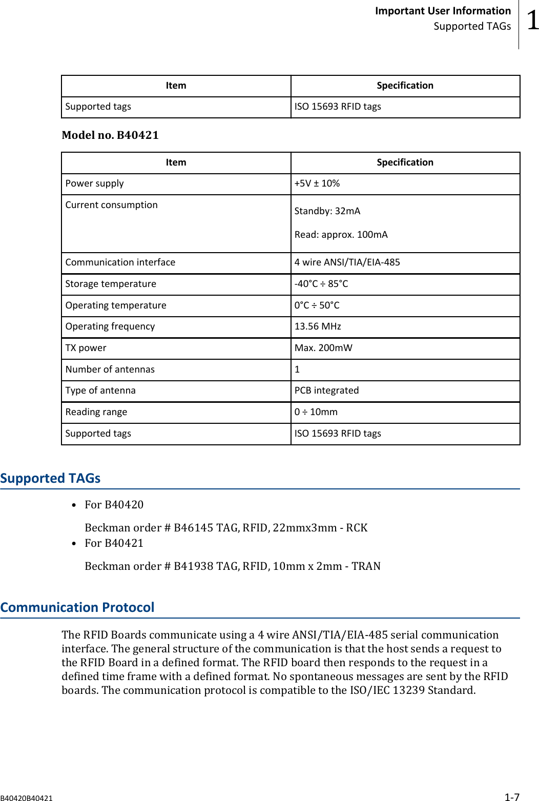
![Field name Size DescriptionCommand 1 Byte Command to execute from the Client. See CommandDescriptionParameter Size 2 Bytes Amount of bytes used in the parameter sectionParameter n Byte(s) Parameter bytes depending on the CommandCRC 2 Bytes Checksum value CRC-16 (a.k.a. CRC-CCITT) as per definition inISO/IEC 13239. See [3.1.1.7] for a detailed descriptionEnd Flag 1 Byte Fixed value of '0xF7'.Response FormatGeneral response formatStart Flag Address Command Data Size Data CRC End FlagThe definition for the fields is in the following table.Field name Size DescriptionStart Flag 1 Byte Fixed value of '0x80'.Address 1 Byte Address of the Client that responds to the host's request.0x00 - 0xFE : Client Address RangeCommand 1 Byte Command that has been executed and that the client isresponding toData Size 2 Bytes Amount of bytes used in the Return sectionData n Byte(s) Data bytes depending on the Command. Contains the ReturnCode.CRC 2 Bytes Checksum value CRC-16 (a.k.a. CRC-CCITT) as per definition inISO/IEC 13239.End Flag 1 Byte Fixed value of '0xF8'.The RFID boards Serial Communication Interface supports the following (request andresponse) commands:• Initialization—Purpose: Initialize the hardware and firmware of the client.—Command Code: 0x01—Format: Return Code / Board ID / Firmware Version Major / Firmware VersionMinor—Input: NA—Output: RFID Board ID, Firmware Version• Set Communication Parameters—Purpose: Sets the communication parameters for the serial communication port.Important User InformationCommunication Protocol 1B40420B40421 1-9](https://usermanual.wiki/Beckman-Coulter-Biomedical/B40421/User-Guide-2705861-Page-13.png)