BIOTRONIK SE and KG TACHNXT implantable cardioverter defibrillator User Manual
BIOTRONIK SE & Co. KG implantable cardioverter defibrillator
UserManual.wiki
>
BIOTRONIK SE and KG
>
TACHNXT User Manual
>
15b_TACHNXT UserMan_Iforia
Contents
1.
15a_TACHNXT UserMan_Ilesto
2.
15b_TACHNXT UserMan_Iforia
15b_TACHNXT UserMan_Iforia
Navigation menu
Upload a User Manual
Namespaces
Wiki Guide
HTML
PDF
Info
Views
User Manual
Discussion / Help
Navigation
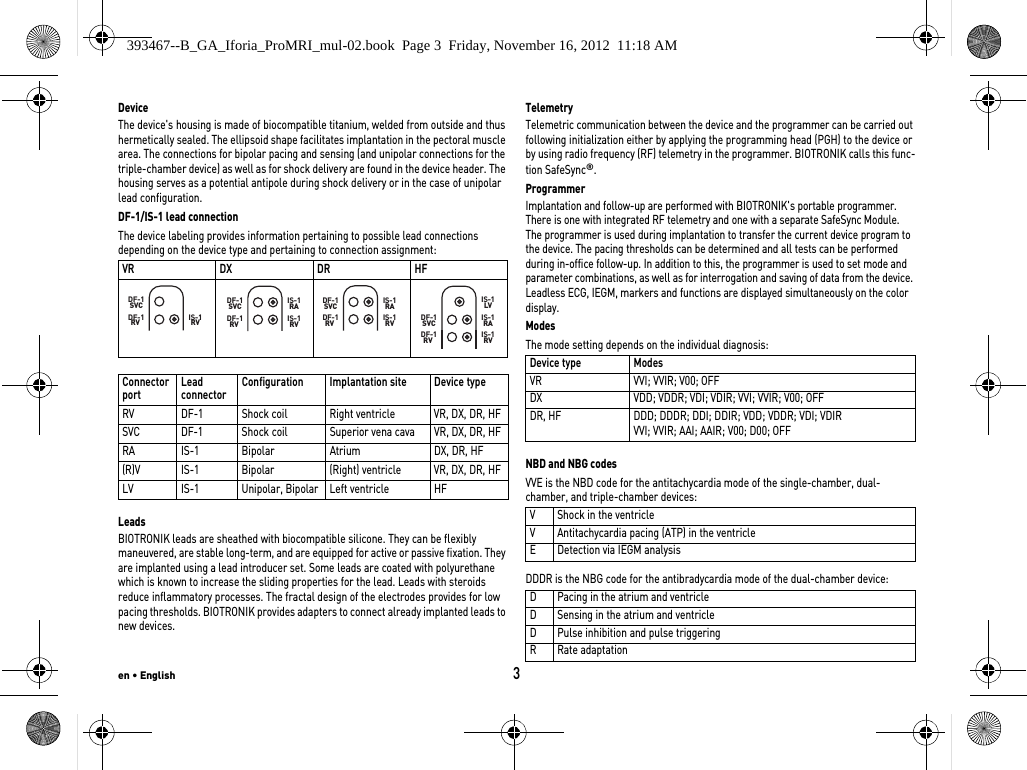
![en • English21Battery DataBattery characteristicsThe following data is provided by the manufacturers: Storage periodThe storage period affects the battery service time.•Devices should be implanted within 19 months between the date of manufacture and the use by date (indicated on the package).•If the ICD is implanted shortly before the use by date, the expected service time may be reduced by up to 16 months.Calculation of service times•The services times have been calculated as follows – in all chambers depending on the device type:—Pulse amplitude: 2.5 V—Pulse width: 0.4 ms—Pacing impedance: 500 Ω—Basic rate: 60 bpm—Home Monitoring: ON, 1 device message each day and 12 transmissions of an IEGM online HD per year—Diagnostic functions and recordings: permanently set•Capacitor reforming is performed 4 times per year and therefore at least 4 maximum charges for shocks have to be assumed per year even if less than 4 are delivered.Calculation of the number of shocksCalculation of the number of shocks: Longevity [in years] x number of shocks per yearIforia 3/5 VR-TService times with GB 2992 or LiS 3410 RA battery: Iforia 5 VR-T DXService times with GB 2992 or LiS 3410 RA battery: Manufacturer GREATBATCH, INC. Clarence, NY 14031 LITRONIK GmbH & Co01796 Pirna, GermanyBattery type GB 2992 LiS 3410 RABattery ID number shown on the programmer34Device type VR, (DX), DR, HFBattery voltage at ERI 2.5 V 2.85 VCharge time at BOS 8 s 8 sCharge time at ERI 10 s 10 sUsable capacity until ERI Iforia 3/5: 1390 mAh Iforia 7: 1600 mAh 1390 mAhUsable capacity until EOS 1730 mAh 1520 mAhStimulation Longevity [in years] at number of shocks per year4 8 1216200%10.42 8.39 7.01 6.03 5.2815%10.14 8.20 6.89 5.93 5.2150%9.55 7.81 6.60 5.72 5.05100%8.81 7.31 6.24 5.45 4.83Stimulation Longevity [in years] at number of shocks per year4 8 1216200%9.48 7.76 6.57 5.70 5.0315%9.24 7.61 6.46 5.61 4.9650%8.75 7.26 6.21 5.42 4.81100%8.12 6.83 5.89 5.17 4.62393467--B_GA_Iforia_ProMRI_mul-02.book Page 21 Friday, November 16, 2012 11:18 AM](https://usermanual.wiki/BIOTRONIK-SE-and-KG/TACHNXT.15b-TACHNXT-UserMan-Iforia/User-Guide-1879843-Page-23.png)
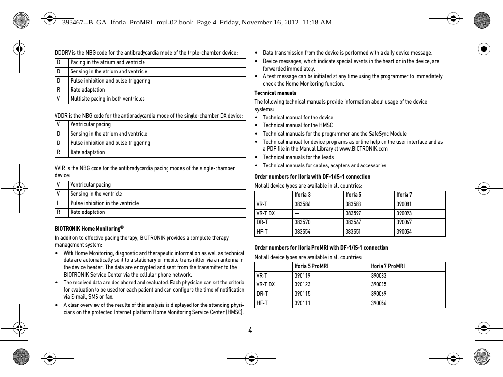
![22Iforia 3/5 DR-TService times with GB 2992 or LiS 3410 RA battery: Iforia 3/5 HF-TService times with GB 2992 or LiS 3410 RA battery: Iforia 7 VR-TService times with GB 2992 battery: Iforia 7 VR-T DXService times with GB 2992 battery: Iforia 7 DR-TService times with GB 2992 battery: Iforia 7 HF-TService times with GB 2992 battery: Stimulation Longevity [in years] at number of shocks per year481216200%9.48 7.76 6.57 5.70 5.0315%9.02 7.45 6.35 5.53 4.8950%8.10 6.81 5.88 5.17 4.61100%7.08 6.07 5.32 4.73 4.26Stimulation Longevity [in years] at number of shocks per year481216200%8.78 7.29 6.23 5.44 4.8215%8.21 6.89 5.94 5.21 4.6550%7.14 6.12 5.35 4.76 4.28100%6.01 5.27 4.69 4.23 3.85Stimulation Longevity [in years] at number of shocks per year481216200%11.78 9.52 7.98 6.87 6.0315%11.48 9.32 7.84 6.76 5.9550%10.81 8.87 7.52 6.53 5.76100%9.99 8.31 7.11 6.21 5.52Stimulation Longevity [in years] at number of shocks per year481216200%10.73 8.82 7.48 6.50 5.7415%10.48 8.65 7.36 6.40 5.6650%9.92 8.26 7.08 6.19 5.50100%9.22 7.77 6.71 5.91 5.27Stimulation Longevity [in years] at number of shocks per year481216200%10.73 8.82 7.48 6.50 5.7415%10.22 8.47 7.23 6.31 5.5950%9.20 7.76 6.70 5.90 5.27100%8.05 6.92 6.07 5.40 4.87Stimulation Longevity [in years] at number of shocks per year481216200%9.96 8.29 7.10 6.20 5.5115%9.33 7.85 6.77 5.95 5.3150%8.12 6.97 6.11 5.43 4.89100%6.85 6.01 5.36 4.83 4.40393467--B_GA_Iforia_ProMRI_mul-02.book Page 22 Friday, November 16, 2012 11:18 AM](https://usermanual.wiki/BIOTRONIK-SE-and-KG/TACHNXT.15b-TACHNXT-UserMan-Iforia/User-Guide-1879843-Page-24.png)
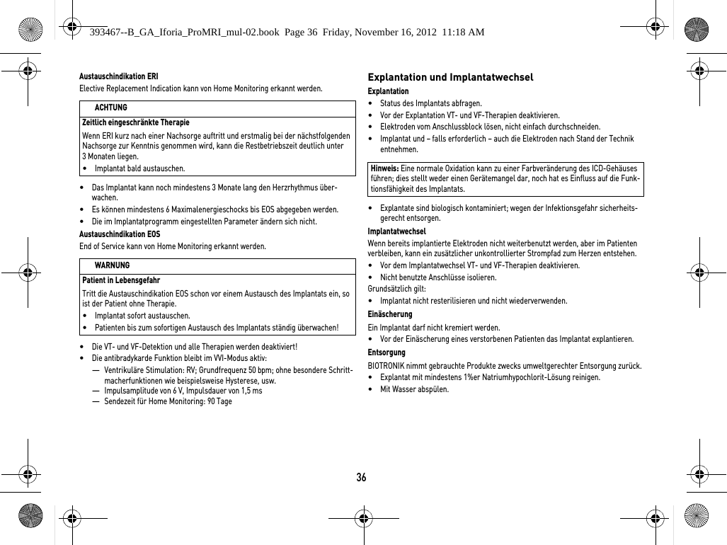
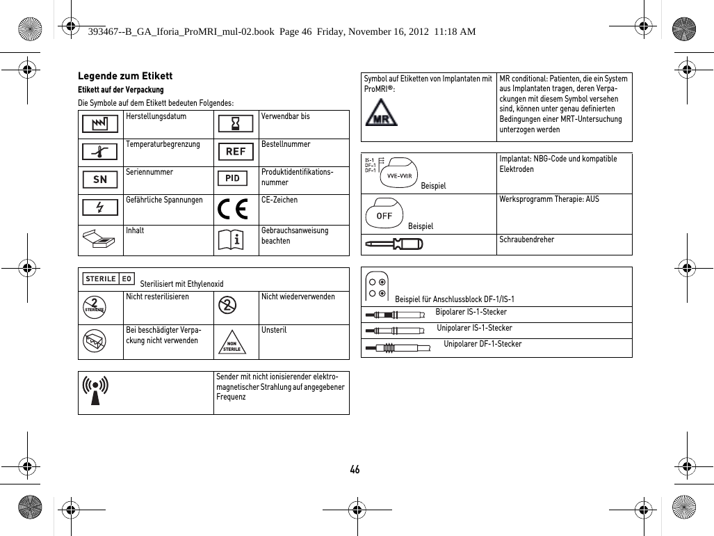
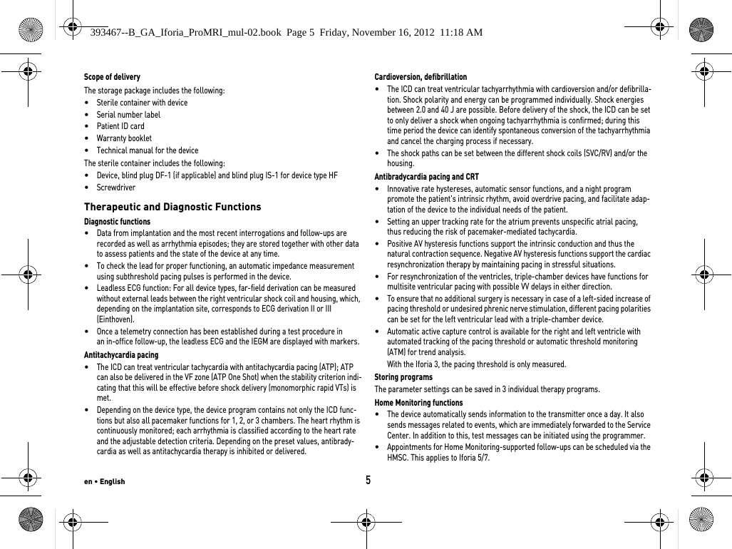
![44LagerdauerDie Lagerdauer beeinflusst die Betriebszeit der Batterie.•Implantate sollen innerhalb von 19 Monaten zwischen Herstellungs- und Haltbar-keitsdatum (Angabe auf der Verpackung) implantiert werden.•Wenn der ICD kurz vor dem Ende des Haltbarkeitsdatums implantiert wird, kann sich die erwartete Betriebszeit um bis zu 16 Monate reduzieren.Berechnung der Betriebszeiten•Die Betriebszeiten wurden wie folgt berechnet – je nach Implantattyp in allen Kammern:—Impulsamplitude: 2,5 V—Impulsdauer: 0,4 ms—Stimulationsimpedanz: 500 Ω—Grundfrequenz: 60 bpm—Home Monitoring: EIN, täglich 1 Implantatnachricht und jährlich 12 Übertragungen eines IEGM-Online-HD—Diagnostikfunktionen und Aufzeichnungen: permanent eingestellt•Es werden 4 Kondensatorformierungen pro Jahr durchgeführt; deshalb müssen mindestens 4 maximale Aufladungen für Schocks pro Jahr angenommen werden, auch wenn weniger als 4 abgegeben werden.Berechnung der SchockanzahlBerechnung der maximalen Schockanzahl: Lebensdauer [Jahre] * Schockanzahl/JahrIforia 3/5 VR-TBetriebszeiten mit Batterie GB 2992 oder LiS 3410 RA: Iforia 5 VR-T DXBetriebszeiten mit Batterie GB 2992 oder LiS 3410 RA: Iforia 3/5 DR-TBetriebszeiten mit Batterie GB 2992 oder LiS 3410 RA: Stimulation Lebensdauer [Jahre] bei Schockanzahl/Jahr481216200 %10,42 8,39 7,01 6,03 5,2815 %10,14 8,20 6,89 5,93 5,2150 %9,55 7,81 6,60 5,72 5,05100 %8,81 7,31 6,24 5,45 4,83Stimulation Lebensdauer [Jahre] bei Schockanzahl/Jahr481216200 %9,48 7,76 6,57 5,70 5,0315 %9,24 7,61 6,46 5,61 4,9650 %8,75 7,26 6,21 5,42 4,81100 %8,12 6,83 5,89 5,17 4,62Stimulation Lebensdauer [Jahre] bei Schockanzahl/Jahr481216200 %9,48 7,76 6,57 5,70 5,0315 %9,02 7,45 6,35 5,53 4,8950 %8,10 6,81 5,88 5,17 4,61100 %7,08 6,07 5,32 4,73 4,26393467--B_GA_Iforia_ProMRI_mul-02.book Page 44 Friday, November 16, 2012 11:18 AM](https://usermanual.wiki/BIOTRONIK-SE-and-KG/TACHNXT.15b-TACHNXT-UserMan-Iforia/User-Guide-1879843-Page-46.png)
![de • Deutsch45Iforia 3/5 HF-TBetriebszeiten mit Batterie GB 2992 oder LiS 3410 RA: Iforia 7 VR-TBetriebszeiten mit Batterie GB 2992: Iforia 7 VR-T DXBetriebszeiten mit Batterie GB 2992: Iforia 7 DR-TBetriebszeiten mit Batterie GB 2992: Iforia 7 HF-TBetriebszeiten mit Batterie GB 2992: Stimulation Lebensdauer [Jahre] bei Schockanzahl/Jahr4 8 12 16 200 %8,78 7,29 6,23 5,44 4,8215 %8,21 6,89 5,94 5,21 4,6550 %7,14 6,12 5,35 4,76 4,28100 %6,01 5,27 4,69 4,23 3,85Stimulation Lebensdauer [Jahre] bei Schockanzahl/Jahr4 8 12 16 200 %11,78 9,52 7,98 6,87 6,0315 %11,48 9,32 7,84 6,76 5,9550 %10,81 8,87 7,52 6,53 5,76100 %9,99 8,31 7,11 6,21 5,52Stimulation Lebensdauer [Jahre] bei Schockanzahl/Jahr4 8 12 16 200 %10,73 8,82 7,48 6,50 5,7415 %10,48 8,65 7,36 6,40 5,6650 %9,92 8,26 7,08 6,19 5,50100 %9,22 7,77 6,71 5,91 5,27Stimulation Lebensdauer [Jahre] bei Schockanzahl/Jahr4 8 1216200 %10,73 8,82 7,48 6,50 5,7415 %10,22 8,47 7,23 6,31 5,5950 %9,20 7,76 6,70 5,90 5,27100 %8,05 6,92 6,07 5,40 4,87Stimulation Lebensdauer [Jahre] bei Schockanzahl/Jahr4 8 1216200 %9,96 8,29 7,10 6,20 5,5115 %9,33 7,85 6,77 5,95 5,3150 %8,12 6,97 6,11 5,43 4,89100 %6,85 6,01 5,36 4,83 4,40393467--B_GA_Iforia_ProMRI_mul-02.book Page 45 Friday, November 16, 2012 11:18 AM](https://usermanual.wiki/BIOTRONIK-SE-and-KG/TACHNXT.15b-TACHNXT-UserMan-Iforia/User-Guide-1879843-Page-47.png)