BIG KING HORN SPEAKER ENT PROPL4TX TRANSMITTER User Manual 500 550 Manual RFID New TX ICONS p65

BIG KING HORN SPEAKER ENT. CO., LTD. TRANSMITTER 500 550 Manual RFID New TX ICONS p65

User Manual Part 5

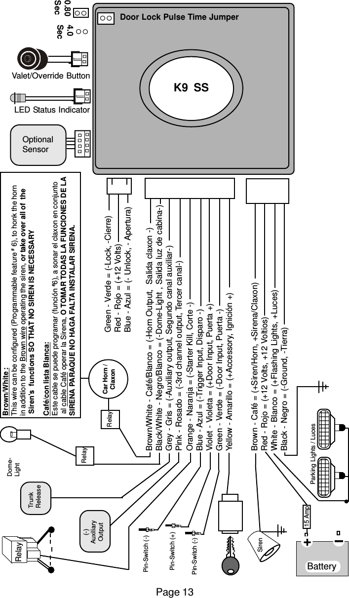
Brown/White :This wire can be configured (Programmable feature # 6), to honk the hornin addition to the Brown wire operating the siren, or take over all of  the Siren’s  functions SO THAT NO SIREN IS NECESSARYCafé/con lista Blanca:Este cable se puede programar (función #6), a sonar el claxon en conjunto al cable Café operar la Sirena, O TOMAR TODAS LA FUNCIONES DE LASIRENA PARAQUE NO HAGA FALTA INSTALAR SIRENA.Brown/White - Café/Blanco = (-Horn Output,  Salida claxon -)Black/White - Negro/Blanco = (-Dome-Light , Salida luz de cabina-)Grey - Gris = (-Auxiliary output, Segundo canal auxiliar-)Pink - Rosado = (-3rd channel output, Tercer canal-)Orange - Naranja = (-Starter Kill, Corte -)Blue - Azul = (-Trigger Input, Disparo -)Violet - Violeta = (+Door Input, Puerta +)Green - Verde = (-Door Input, Puerta -)Yellow - Amarillo = (+Accessory, Ignición +)Brown - Café = (+Siren/Horn, +Sirena/Claxon)Red - Rojo = (+12 Volts, +12 Voltios)White - Blanco = (+Flashing Lights, +Luces)Black - Negro = (-Ground, -Tierra)Valet/Override Button0.80Sec4.0SecDoor Lock Pulse Time JumperLED Status IndicatorOptionalSensorK9  SSGreen - Verde = (-Lock, -Cierre)Red - Rojo = (+12 Volts)Blue - Azul = (- Unlock, - Apertura)Siren   Pin-Switch (-)   Pin-Switch (-)Battery   Pin-Switch (+)15 Amp+      Parking Lights / LucesRelayTrunkReleaseRelayRelay Car Horn /ClaxonDome-Light(-)AuxiliaryOutputPage 13
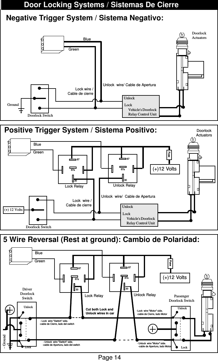
Page 14Negative Trigger System / Sistema Negativo:Doorlock SwitchGroundVehicle's DoorlockRelay Control UnitLockUnlock Lock wire /Cable de cierreUnlock  wire/ Cable de Apertura+DoorlockActuators5 Wire Reversal (Rest at ground): Cambio de Polaridad:Positive Trigger System / Sistema Positivo:Doorlock Switch(+) 12 VoltsVehicle's DoorlockRelay Control UnitLockUnlock Lock  wire /Cable de cierreUnlock  wire/  Cable de Apertura+DoorlockActuators(+)12 VoltsUnlock UnlockPassengerDoorlock SwitchDriverDoorlockSwitch  - Lock  wire "Switch" side.           -cable de Cierre, lado del switch  -Lock  wire "Motor" side.           -cable de Cierre, lado MotorCut both Lock andUnlock wires in car- Unlock  wire "Switch" side.           -cable de Apertura, lado del switchLock Lock- Ground- Unlock  wire "Motor" side.           -cable de Apertura, lado MotorGreenBlueFuse308787a308787aGreenBlueLock Relay Unlock RelayFuse308787a308787aGreenBlueLock Relay Unlock Relay(+)12 VoltsDoor Locking Systems / Sistemas De Cierre
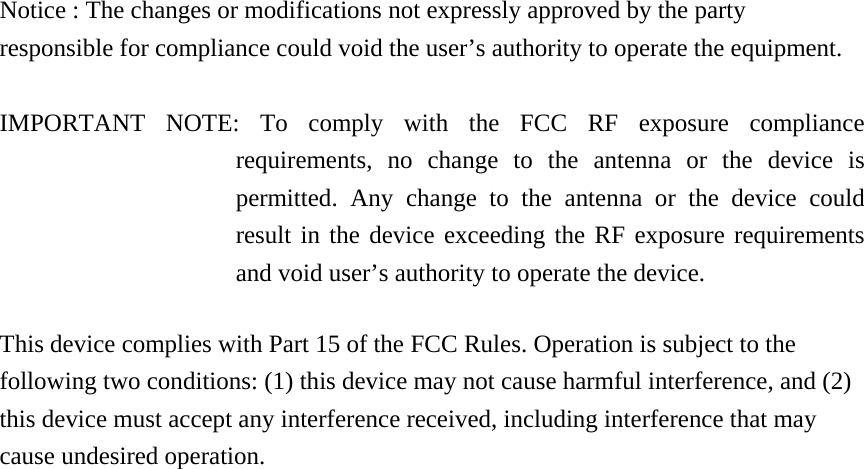
Notice : The changes or modifications not expressly approved by the party responsible for compliance could void the user’s authority to operate the equipment.  IMPORTANT NOTE: To comply with the FCC RF exposure compliance requirements, no change to the antenna or the device is permitted. Any change to the antenna or the device could result in the device exceeding the RF exposure requirements and void user’s authority to operate the device.  This device complies with Part 15 of the FCC Rules. Operation is subject to the following two conditions: (1) this device may not cause harmful interference, and (2) this device must accept any interference received, including interference that may cause undesired operation.

Navigation menu